EP0433251B1 - A method and an arrangement for adjusting the settings of flow regulators - Google Patents
A method and an arrangement for adjusting the settings of flow regulators Download PDFInfo
- Publication number
- EP0433251B1 EP0433251B1 EP90850364A EP90850364A EP0433251B1 EP 0433251 B1 EP0433251 B1 EP 0433251B1 EP 90850364 A EP90850364 A EP 90850364A EP 90850364 A EP90850364 A EP 90850364A EP 0433251 B1 EP0433251 B1 EP 0433251B1
- Authority
- EP
- European Patent Office
- Prior art keywords
- pressure
- lever
- fluid
- flow
- operating unit
- Prior art date
- Legal status (The legal status is an assumption and is not a legal conclusion. Google has not performed a legal analysis and makes no representation as to the accuracy of the status listed.)
- Revoked
Links
Images

Classifications
-
- G—PHYSICS
- G05—CONTROLLING; REGULATING
- G05D—SYSTEMS FOR CONTROLLING OR REGULATING NON-ELECTRIC VARIABLES
- G05D7/00—Control of flow
- G05D7/01—Control of flow without auxiliary power
- G05D7/0193—Control of flow without auxiliary power using hydraulic or pneumatic amplifiers, relays or transmitters
Definitions
- the present invention relates to a method and to an arrangement for controlling a fluid-flow regulating device, comprising maintaining a pressure or pressure difference in a fluid flow duct at a selected, substantially constant value, causing said pressure or pressure difference to act on a pivotally supported lever device so as to move the lever in a first direction of rotation, whereas the weight of the lever moves it in a second direction of rotation, which is opposite to the said first direction of rotation, so that said lever is in a position of balance between its two terminal positions of rotation when the selected value of said pressure of pressure difference is reached, driving the regulation device via an operating unit by means of a driving fluid flow established by the fluid-flow in said duct between a chosen loaction at said flow duct in which the fluid is not regulated by the regulating device, and the atmosphere and using the movement of the lever in the said first direction of rotation to cause at least part of the driving fluid flow to pass into the operating unit, when so required for control purposes.
- This arrangement solves many problems where previously it was possible to use only manually adjustable throttle valves, since it has not been feasible to use earlier arrangements of this kind at reasonable costs, because of their imprecision and because of the poor control function that they provide.
- One general problem in this regard is that subsequent to establishing that the air flow to one room or location is correct, or at least lies within acceptable tolerances, a subsequent change in the setting of the valve function in a duct or channel in another room or location in the same building complex will result in a change in the setting of the first mentioned location.
- the task of adjusting the valve settings in different locations or rooms of a building is therefore particularly time-consuming and it is extremely seldom that the desired air flow to respective locations can be achieved satisfactorily in practice.
- One method of solving the aforesaid adjustment problem is to replace the cylinder-mounted pressure-detecting body with a lever device constructed to as to be self-adjusting in relation to the prevailing pressure or pressure difference in a manner such as to be held in equilibrium between its two terminal positions when the selected pressure or pressure difference is reached.
- the centre of gravity of this lever device can be displaced in various ways, either manually or automatically. Arrangements and methods which utilize such lever devices operating in accordance with the principles set forth in the introductory portion are described in DE-A-2432660, in EP-A-0 192 335 and in DE-A-24 32 660.
- One drawback with these known arrangements and methods is that control cannot be achieved with the accuracy desired in present day ventilation systems, which are becoming more and more sophisticated.
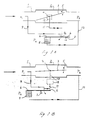
- Figure 1 illustrates schematicaly an air flow duct or channel 1 through which air is caused to flow under the influence of a fan (not shown) located on the left of the duct.
- the direction of air flow is shown with an arrow.
- the pressure P1 in the flow duct 1 shall be regulated to a selected value, i.e. the set-point value, with the aid of a regulating device 2 and a throttle valve, or butterfly valve 3 which is pivotally mounted on a shaft 4 for movement in directions indicated by arrows 5, said shaft, in the illustrated case, extending at right angles to the horizontal plane.
- the pressure prevailing at each moment in time is the real value and is designated P2 in the illustrated case.
- the reference sign P a signifies the air pressure in the room.
- a lever device 6 having one or two arms is supported at its fulcrum or turning point by an edge 7.
- the left-hand arm of the lever device is raised and lowered under the action of the pressure P2.
- the illustrated embodiment employs a downwardly-open bellows 8 which at one end is attached in an airtight fashion to the left arm of the lever device 6, whereas the other, open end of said bellows is attached to a fixed point.
- a first line 9 extends from the flow channel at a location upstream of the regulating device 2, where the pressure P1 prevails, so as to enable the line to be opened and closed at its outlet end 9a by the lever device 6 upon rotation of the arm around its moment axis in respective directions on the fulcrum edge 7.
- a second line 10 connects the bellows 8 with the selected point in the duct 1 at which the pressure has been adjusted by the regulating device 2 and assumes the value P2 at each moment in time.
- a third line 11 functions to connect a fluid-driven, valve-operating unit 12 with the line 9 at a location immediately above the outlet end 9a of said line 9 and at an angle to the line 9 such as to create an ejector effect which is able to contribute to the air flow in the line 11.
- the operating unit 12 operates the valve 3 in response to the flow of air into and out of said unit through the line 11 and in response to the flow in said line 11.
- the operating unit 12 can be positioned within the flow duct 1 in the regulating device 2, or externally of the duct, as illustrated in Figure 1B.
- the operating unit 12 may be constructed to activate the valve 3 directly, as indicated in Figure 1A, or indirectly as indicated in Figure 1B.
- This ejector effect enables the operating unit 12 to be emptied rapidly, despite the low pressure levels prevailing in the case of the applications concerned here, for instance ventilation systems.
- atmospheric pressure will never be reached in the operating unit 12 in the absence of the ejector effect from the line 9, unless mechanical auxiliaries, such as strong return springs, are provided for emptying the operating unit 12.
- mechanical auxiliaries such as strong return springs
- a greater pressure is required, however, for delivering fluid to the operating unit 12, and the arrangement will not then operate as a complete arrangement at the low pressures prevailing in conventional ventilation systems.
- the arrangement can then only be caused to function satisfactorily by enlarging the active surfaces of the operating unit 12 to an extent sufficient for the purpose intended, although the outer dimensions of the unit would then be prohibitive for the purposes intended.
- the outlet 9a of the line 9 is directed onto and sealingly abuts the same arm of the lever device 6 as that to which the bellows 8 is attached.
- the lever device 6 of this embodiment may have only one single arm.
- the outlet 9a will be closed completely by the lever device 6, due to expansion of the bellows 8.
- the arm 6 is then located in its higher terminal position, therewith establishing direct communication between the lines 9 and 11. All air will now flow from the line 9, through the line 11 and into the operating unit 12, which therewith throttles the valve 3 and causes the pressure P2 to fall.
- This position of equilibrium can be readily selected at some point between the terminal positions of the lever device 6, by moving its centre-of-gravity point, therewith enabling a corresponding pressure P2 to be held substantially constant.
- the pressure P2 can be set at a selected value, by changing the centre-of-gravity position of the lever 6, for instance by displacing a weight (not shown) along said lever device.
- the outlet 9a of the line 9 is directed onto the right arm of the lever device 6.
- the operating unit 12 is then configured so that the valve 3 will be opened at an elevated pressure and vice versa, through the action of a device indicated at 13.
- the outlet 9a is opened successively until the lever device 6 reaches one terminal position of its rotation, in which all air through the line 9 is able to exit freely and the operating unit 12 is also emptied of air as a result of the influence exerted by atmospheric pressure and the ejector effect provided by the flow in the line 9, so as to close the valve 3.
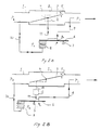
- Figure 2 illustrates schematically an exhaust air system, in which Figure the Figure 2A illustrates a directly acting embodiment and Figure B illustrates an indirectly acting embodiment.
- system control is effected principly in the same manner as that described with reference to the supply air system illustrated in Figure 1, although in the system illustrated in Figure 2 the pressures P1 and P2 have been reversed geographically in the duct, where a fan (not shown) to the right of the duct draws air in the direction illustrated by an arrow.
- the pressure P2 upstream of the regulating device 2 is thus regulated to a selected constant value.
- the operating unit 12 is constructed so as to be influenced on its outside by the pressure P1.
- the maximum force which causes the operating unit 12 to open and close the valve 3 is proportional to the pressure difference P1-P2, whereas the smallest force is proportional to the pressure difference P a -P2.
- Corresponding values for the indirectly acting embodiment illustrated in Figure 1B are maximum P1-P a and minimum P a -P a (i.e. zero).
- corresponding forces are maximum P a -P1 and minimum P1-P1 (i.e. zero) in the case of the directly acting system and maximum P a -P1 and minimum P1-P1 (i.e. zero) respectively with the indirectly acting system.
- the pressure differences can also be regulated by using two regulating devices and by regulating and controlling pressure at two points in a corresponding manner.
- two control systems of the aforedescribed kind can be caused to coact with one another. It is also possible to permit each pressure difference to act on solely one lever device, for instance by arranging each of two bellows on a respective arm of the lever.
- FIG. 3 illustrates a preferred arrangement for controlling a regulating device, here called a control unit.
- the control unit is generallly referenced 30 and includes a housing 31, 32, wherein 31 identifies the bellows part of the housing and 32 its valve part.
- a device 34 Arranged in the housing 31, 32 is a bellows 33 and a device 34, referred to her as a balance lever.
- the balance lever device 34 has provided thereon a weight 35 which can be displaced along the lever arm with the aid of a setting screw 36.
- the balance lever 34 and the setting screw 36 with weight 35 are connected by means of a locking nut 37.
- the open end of the bellows 33 is fitted onto a bellows holder 38, which extends slightly into the bellows 33, so as to prevent said bellows from "balooning" out of the control unit 30 when the bellows 33 is subjected to high overpressures.
- a hose connection 38A for connection to a flow duct at the location thereon at which a selected pressure shall be held constant.
- the bellows holder 38, and therewith also the bellows 33, is affixed to the bellows part 31 of the housing by means of a locking ring 39.
- a pipe branching 40 having a straight through-passing part 40a and a part 40b at right angles thereto is screwed firmly to the valve part 32 of the housing, so that one end of the through-passing part can lie sealingly against the balance lever 34.
- the part 40b of the pipe branching 40 may also extend at an angle smaller than 90° to that part of the through-passing part 40a which faces upwards in the drawing.
- the balance lever 34 has to the left of the drawing a ring-shaped part which is attached to the bellows 33 in an airtight fashion and which balances on an edge 41 mounted in the valve part 32 of the housing.
- the length-extension of the edge in abutment with the balance lever 34 is relatively long, so as to render negligible deformation resulting from wear over a long period of use.
- the gravitational force exerted by the balance lever 34 constitutes a reference pressure to the pressure prevailing in bellows 33.
- the position taken by the balance lever 34 decides how much air shall flow to or from an operating unit of a regulating device through the transverse pipe of the pipe branching 40, as earlier described.
- the third end of the pipe branching 40 is intended to be connected to a supply air duct having a regulating device mounted therein, as earlier described.
- the feedback system is influenced by the mass inertia exhibited by the balance lever 34.
- One method of reducing the mass of the arm is to drill so-called lightening holes therein.
- the weight 35 moves in elongated grooves on the balance lever 34. Because the trunnions of the weight 35 are visible from both sides of the lever 34, the position of the weight, and therewith the pressure set on the bellows 33, can be read-off directly.
- the lever 34 is preferably provided with a scale which facilitates reading of the set pressure.
- the sise of the weight 35 is suitably adapted in a manner which will enable simple adjustments of a single pascal in pressure to be made, while keeping the construction of the lever 34 compact at the same time. A small weight 35 will therewith provide a more widely spaced scale and more accurate adjustment, but also a larger lever 34.
- the upper pipe-part of the pipe branching 40 is preferably provided with a velocity-increasing nozzle 42 which will contribute to further improving the ejector effect and therewith enabling rapid evacuation of the operating unit through said ejector effect in those instances when the operating unit, and therewith the valve, is to be adjusted to one of its terminal positions, as before described.
Abstract
Description
- The present invention relates to a method and to an arrangement for controlling a fluid-flow regulating device, comprising maintaining a pressure or pressure difference in a fluid flow duct at a selected, substantially constant value, causing said pressure or pressure difference to act on a pivotally supported lever device so as to move the lever in a first direction of rotation, whereas the weight of the lever moves it in a second direction of rotation, which is opposite to the said first direction of rotation, so that said lever is in a position of balance between its two terminal positions of rotation when the selected value of said pressure of pressure difference is reached, driving the regulation device via an operating unit by means of a driving fluid flow established by the fluid-flow in said duct between a chosen loaction at said flow duct in which the fluid is not regulated by the regulating device, and the atmosphere and using the movement of the lever in the said first direction of rotation to cause at least part of the driving fluid flow to pass into the operating unit, when so required for control purposes.
- An arrangement for adjusting the settings of flow regulators is known from our earlier Patent Specification No. SE-B-458 802 and from the corresponding European Specification No. EP-A-0 285 588. According to this known technique, control is effected with the aid of a cylinder assembly which has a vertical cylinder axis and in which there is mounted a readily moved, pressure-detecting body which, together with said cylinder, defines a pressure space which communicates with a ventilation passageway at a selected point therein. The pressuredetecting body has a mass which corresponds to a chosen pressure at said point in the passageway and is intended to balance the pressure acting on the body. This arrangement solves many problems where previously it was possible to use only manually adjustable throttle valves, since it has not been feasible to use earlier arrangements of this kind at reasonable costs, because of their imprecision and because of the poor control function that they provide. One general problem in this regard is that subsequent to establishing that the air flow to one room or location is correct, or at least lies within acceptable tolerances, a subsequent change in the setting of the valve function in a duct or channel in another room or location in the same building complex will result in a change in the setting of the first mentioned location. The task of adjusting the valve settings in different locations or rooms of a building is therefore particularly time-consuming and it is extremely seldom that the desired air flow to respective locations can be achieved satisfactorily in practice. Although our earlier proposed arrangement is able to solve many problems of this nature, the work involved in adjusting the valves is highly complicated, even with this known arrangement, and it is often necessary to change the mass of the pressure-detecting body manually, with the aid of different changeable tare weights. Consequently, there is a need for an arrangement which will enable such adjustments to be made in a simpler and more flexible fashion, particularly in the case of more complicated ventilation systems in large building complexes in which disturbances of the aforesaid kind occur to such extent as to cause the necessary adjustments to be both time-consuming and not-readily achievable.
- One method of solving the aforesaid adjustment problem is to replace the cylinder-mounted pressure-detecting body with a lever device constructed to as to be self-adjusting in relation to the prevailing pressure or pressure difference in a manner such as to be held in equilibrium between its two terminal positions when the selected pressure or pressure difference is reached. The centre of gravity of this lever device can be displaced in various ways, either manually or automatically. Arrangements and methods which utilize such lever devices operating in accordance with the principles set forth in the introductory portion are described in DE-A-2432660, in EP-A-0 192 335 and in DE-A-24 32 660. One drawback with these known arrangements and methods, however, is that control cannot be achieved with the accuracy desired in present day ventilation systems, which are becoming more and more sophisticated.
- It has now been found possible to provide a method for adjusting the settings of regulating devices in accordance with the introduction which, in relation to the present standpoint of techniques will enable adjustments to be made much more simply than was previously the case while, at the same time, maintaining a high degree of regulator accuracy. The inventive method is set forth in the following
Claim 1. The invention also relates to an arrangement for carrying out the method, this arrangement being set forth in the followingClaims 2. - The invention will now be described in more detail with reference to the accompanying drawings, Figures 1 and 2 of which each illustrate the principles of the inventive method applied to a terminal air supply circuit in the ventilation system and to an exhaust-air circuit therein; and Figure 3 illustrates a preferred embodiment of the arrangement for carrying out the method.
- Figure 1 illustrates schematicaly an air flow duct or
channel 1 through which air is caused to flow under the influence of a fan (not shown) located on the left of the duct. The direction of air flow is shown with an arrow. The pressure P₁ in theflow duct 1 shall be regulated to a selected value, i.e. the set-point value, with the aid of aregulating device 2 and a throttle valve, orbutterfly valve 3 which is pivotally mounted on ashaft 4 for movement in directions indicated byarrows 5, said shaft, in the illustrated case, extending at right angles to the horizontal plane. The pressure prevailing at each moment in time is the real value and is designated P₂ in the illustrated case. The reference sign Pa signifies the air pressure in the room. Alever device 6 having one or two arms is supported at its fulcrum or turning point by anedge 7. The left-hand arm of the lever device is raised and lowered under the action of the pressure P₂. Although this can be effected in several ways, the illustrated embodiment employs a downwardly-open bellows 8 which at one end is attached in an airtight fashion to the left arm of thelever device 6, whereas the other, open end of said bellows is attached to a fixed point. Afirst line 9 extends from the flow channel at a location upstream of theregulating device 2, where the pressure P₁ prevails, so as to enable the line to be opened and closed at its outlet end 9a by thelever device 6 upon rotation of the arm around its moment axis in respective directions on thefulcrum edge 7. Asecond line 10 connects thebellows 8 with the selected point in theduct 1 at which the pressure has been adjusted by the regulatingdevice 2 and assumes the value P₂ at each moment in time. Athird line 11 functions to connect a fluid-driven, valve-operating unit 12 with theline 9 at a location immediately above the outlet end 9a of saidline 9 and at an angle to theline 9 such as to create an ejector effect which is able to contribute to the air flow in theline 11. Theoperating unit 12 operates thevalve 3 in response to the flow of air into and out of said unit through theline 11 and in response to the flow in saidline 11. As illustrated in Figure 1A, theoperating unit 12 can be positioned within theflow duct 1 in theregulating device 2, or externally of the duct, as illustrated in Figure 1B. Theoperating unit 12 may be constructed to activate thevalve 3 directly, as indicated in Figure 1A, or indirectly as indicated in Figure 1B. - In this regard, it is important with respect to regulating accuracy that the
operating unit 12 can be emptied of air sufficiently when thethrottle 3 shall be fully closed or fully opened. This is achieved in accordance with the present invention through the special ejector effect, as indicated above. - This ejector effect enables the
operating unit 12 to be emptied rapidly, despite the low pressure levels prevailing in the case of the applications concerned here, for instance ventilation systems. Thus, atmospheric pressure will never be reached in theoperating unit 12 in the absence of the ejector effect from theline 9, unless mechanical auxiliaries, such as strong return springs, are provided for emptying theoperating unit 12. In cases such as these, a greater pressure is required, however, for delivering fluid to theoperating unit 12, and the arrangement will not then operate as a complete arrangement at the low pressures prevailing in conventional ventilation systems. The arrangement can then only be caused to function satisfactorily by enlarging the active surfaces of theoperating unit 12 to an extent sufficient for the purpose intended, although the outer dimensions of the unit would then be prohibitive for the purposes intended. - In the case of the directly acting embodiment illustrated in Figure 1A, the outlet 9a of the
line 9 is directed onto and sealingly abuts the same arm of thelever device 6 as that to which thebellows 8 is attached. Thus, thelever device 6 of this embodiment may have only one single arm. When the pressure P₂ is sufficiently high, the outlet 9a will be closed completely by thelever device 6, due to expansion of thebellows 8. Thearm 6 is then located in its higher terminal position, therewith establishing direct communication between thelines line 9, through theline 11 and into theoperating unit 12, which therewith throttles thevalve 3 and causes the pressure P₂ to fall. When the pressure P₂ falls, thebellows 8 is squeezed or collapsed and when the pressure P₂ has reached a sufficiently low value, the outlet 9a of theline 9 will be fully opened as a result of downward movement of thelever device 6 at the contact position. All air through theline 9 can thus flow freely through the outlet 9a and the air present in theoperating unit 12 will be caused to flow out through theline 11, under the influence of the pressure P₂, thereby opening thethrottle valve 3. Thus, when apposition of equilibrium or balance is reached at some point between these terminal positions of thelever device 6, no air will flow to or from theoperating unit 12 through theline 11. This position of equilibrium can be readily selected at some point between the terminal positions of thelever device 6, by moving its centre-of-gravity point, therewith enabling a corresponding pressure P₂ to be held substantially constant. Thus, when thelever device 6 is in equilibrium, the pressure P₂ can be set at a selected value, by changing the centre-of-gravity position of thelever 6, for instance by displacing a weight (not shown) along said lever device. - In the case of the indirectly acting embodiment illustrated in Figure 1B, the outlet 9a of the
line 9 is directed onto the right arm of thelever device 6. Theoperating unit 12 is then configured so that thevalve 3 will be opened at an elevated pressure and vice versa, through the action of a device indicated at 13. When the pressure P₂ increases, the outlet 9a is opened successively until thelever device 6 reaches one terminal position of its rotation, in which all air through theline 9 is able to exit freely and theoperating unit 12 is also emptied of air as a result of the influence exerted by atmospheric pressure and the ejector effect provided by the flow in theline 9, so as to close thevalve 3. When the pressure P₂ falls, the outlet 9a is closed successively until the right arm of thelever device 6 sealingly abuts the outlet 9a, saidlever device 6 having then reached its second terminal position of rotation. All air will now flow through theline 9 and into theoperating unit 12, through theline 11, wherewith the pressure in theoperating unit 12 increases and thevalve 3 is opened and the pressure P₂ rises. The same conditions as those described above with reference to Figure 1A apply when the lever device is in equilibrium or balanced. - Figure 2 illustrates schematically an exhaust air system, in which Figure the Figure 2A illustrates a directly acting embodiment and Figure B illustrates an indirectly acting embodiment. In operation, system control is effected principly in the same manner as that described with reference to the supply air system illustrated in Figure 1, although in the system illustrated in Figure 2 the pressures P₁ and P₂ have been reversed geographically in the duct, where a fan (not shown) to the right of the duct draws air in the direction illustrated by an arrow. In this case, the pressure P₂ upstream of the regulating
device 2 is thus regulated to a selected constant value. Theoperating unit 12 is constructed so as to be influenced on its outside by the pressure P₁. In the case of the embodiment illustrated in Figure 1A, the maximum force which causes theoperating unit 12 to open and close thevalve 3 is proportional to the pressure difference P₁-P₂, whereas the smallest force is proportional to the pressure difference Pa-P₂. Corresponding values for the indirectly acting embodiment illustrated in Figure 1B are maximum P₁-Pa and minimum Pa-Pa (i.e. zero). In the embodiments illustrated in Figure 2, corresponding forces are maximum Pa-P₁ and minimum P₁-P₁ (i.e. zero) in the case of the directly acting system and maximum Pa-P₁ and minimum P₁-P₁ (i.e. zero) respectively with the indirectly acting system. - In a manner corresponding to that illustrated in Figures 1 and 2, the pressure differences can also be regulated by using two regulating devices and by regulating and controlling pressure at two points in a corresponding manner. In this case, two control systems of the aforedescribed kind can be caused to coact with one another. It is also possible to permit each pressure difference to act on solely one lever device, for instance by arranging each of two bellows on a respective arm of the lever.
- Figure 3 illustrates a preferred arrangement for controlling a regulating device, here called a control unit.
- The control unit is generallly referenced 30 and includes a
housing housing device 34, referred to her as a balance lever. Thebalance lever device 34 has provided thereon aweight 35 which can be displaced along the lever arm with the aid of a settingscrew 36. Thebalance lever 34 and the settingscrew 36 withweight 35 are connected by means of a lockingnut 37. The open end of thebellows 33 is fitted onto abellows holder 38, which extends slightly into thebellows 33, so as to prevent said bellows from "balooning" out of thecontrol unit 30 when the bellows 33 is subjected to high overpressures. Provided in the open end of the bellows-holder 38 is ahose connection 38A for connection to a flow duct at the location thereon at which a selected pressure shall be held constant. The bellowsholder 38, and therewith also thebellows 33, is affixed to thebellows part 31 of the housing by means of a lockingring 39. A pipe branching 40 having a straight through-passing part 40a and a part 40b at right angles thereto is screwed firmly to thevalve part 32 of the housing, so that one end of the through-passing part can lie sealingly against thebalance lever 34. The part 40b of the pipe branching 40 may also extend at an angle smaller than 90° to that part of the through-passing part 40a which faces upwards in the drawing. Thebalance lever 34 has to the left of the drawing a ring-shaped part which is attached to thebellows 33 in an airtight fashion and which balances on anedge 41 mounted in thevalve part 32 of the housing. The length-extension of the edge in abutment with thebalance lever 34 is relatively long, so as to render negligible deformation resulting from wear over a long period of use. The gravitational force exerted by thebalance lever 34 constitutes a reference pressure to the pressure prevailing in bellows 33. In principle, the position taken by thebalance lever 34 decides how much air shall flow to or from an operating unit of a regulating device through the transverse pipe of the pipe branching 40, as earlier described. The third end of the pipe branching 40 is intended to be connected to a supply air duct having a regulating device mounted therein, as earlier described. - Since the
balance lever 34 is a movable part in thecontrol unit 30, the feedback system is influenced by the mass inertia exhibited by thebalance lever 34. The greater the mass inertia the smaller the margin towards instability and self-oscillation. Consequently, it is important to keep the mass of thelever device 34 as low as possible. One method of reducing the mass of the arm is to drill so-called lightening holes therein. - In order to facilitate movement of the centre-of-gravity of the
balance lever 34, theweight 35 moves in elongated grooves on thebalance lever 34. Because the trunnions of theweight 35 are visible from both sides of thelever 34, the position of the weight, and therewith the pressure set on thebellows 33, can be read-off directly. Thelever 34 is preferably provided with a scale which facilitates reading of the set pressure. The sise of theweight 35 is suitably adapted in a manner which will enable simple adjustments of a single pascal in pressure to be made, while keeping the construction of thelever 34 compact at the same time. Asmall weight 35 will therewith provide a more widely spaced scale and more accurate adjustment, but also alarger lever 34. - The upper pipe-part of the pipe branching 40 is preferably provided with a velocity-increasing
nozzle 42 which will contribute to further improving the ejector effect and therewith enabling rapid evacuation of the operating unit through said ejector effect in those instances when the operating unit, and therewith the valve, is to be adjusted to one of its terminal positions, as before described. - The invention is not restricted to the aforedescribed and illustrated embodiments since various modifications can be made. For instance, the principles of the invention can be applied for controlling fluids other than air, to which latter primary reference is made.
Claims (5)
- A method for controlling a fluid-flow regulating device (2) in order to maintain a pressure or pressure difference in a fluid flow duct (1) at a selected, substantially constant value (P₂) comprising, causing said pressure or pressure difference (P₂) to act on a pivotally supported lever device (6) so as to move the lever (6) in a first direction of rotation, whereas the weight of the lever (6) moves it in a second direction of rotation, which is opposite to the said first direction of rotation, so that said lever (6) is in a position of balance between its two terminal positions of rotation when the selected value (P₂) of said pressure or pressure difference is reached,
driving the regulation device (2) via an operating unit (12) by means of a driving fluid flow (9) established by the actual pressure difference between the atmosphere pressure (Pa) and the pressure (P₁) at a chosen location at which the fluid is not regulated by the regulation device (2),
using the movement of the lever (6) in the said first direction of rotation to cause at least part of the driving fluid flow (9) to pass into the operating unit (12), when so required for control purposes, characterized by using the movement of the lever (6) in the said second direction of rotation to cause an increased flow of driving fluid and thereby providing on ejector effect which causes fluid to flow out of the operating unit (12), when so required for control purposes, said ejector effect adapted to permit emptying the operating unit (12) substantially completely, so as to precisely control the flow of fluid respectively into and out of the operating unit (12) of the regulating device (2) in accurate response to the pressure or pressure difference (P₂) acting on the lever device (6) at each moment in time. - An arrangement for controlling a fluid-flow regulating device (2) operating to maintain a pressure or presure difference in a fluid flow duct (1) at a selected substantially constant value (P₂), said arrangement comprising a pivotally supported lever device (6,34); a bellows (8,33) which coacts with the lever device (6,34) and moves the lever in one rotational direction, whereas the weight of the lever moves it in the opposite rotational direction, and which bellows (8,33) is intended to influence the position of the lever device (6,34) and is driven by the pressure (P₂) regulated by the regulating device (2), characterized by a pipe branching (40) having a straight through-passing part (40a) and a part (40b) which extends at an angle to the throughpassing part (40a), said pipe branching (40) functioning as an ejector for emptying an operation unit (12) of said regulating device (2), when a fluid flow through the straight through-passing part (40a) increases; one end of said through-passing part (40a) being capable of being brought into sealing abutment with one of the arms of the lever device (6, 34); whereas the corresponding other end of said through-passing part is intended to communicate with the flow duct (1) at a location therein at which the fluid flow is not regulated by the regulating device (2) and the angle part (40b) of said pipe branching is intended to communicate with the fluid-driven operating unit (12) forming part of the regulating device (2) and extends at an angle such as to produce an ejector effect in said pipe branching (40).
- An arrangement according to Claim 2 for maintaining a pressure difference of selected value, characterized in that said arrangement includes a lever device (6,34) having two arms; a further bellows (8,33) coacting with said arm, and a further pipe branching (40) arranged in a corresponding manner.
- An arrangement according to Claim 2 or 3, characterized in that each pipe branching (40) is provided with a velocity increasing nozzle (42) at that end of the straight throughpassing part (40a) which is intended to communicate with the flow duct (1).
- An arrangement according to Claim 4, characterized in that the nozzle (42) is exchangeable.
Applications Claiming Priority (2)
| Application Number | Priority Date | Filing Date | Title |
|---|---|---|---|
| SE8903831A SE8903831D0 (en) | 1989-11-15 | 1989-11-15 | SET AND DEVICE TO CONTROL A CONTROLLER FOR FLUIDS |
| SE8903831 | 1989-11-15 |
Publications (2)
| Publication Number | Publication Date |
|---|---|
| EP0433251A1 EP0433251A1 (en) | 1991-06-19 |
| EP0433251B1 true EP0433251B1 (en) | 1995-06-21 |
Family
ID=20377482
Family Applications (1)
| Application Number | Title | Priority Date | Filing Date |
|---|---|---|---|
| EP90850364A Revoked EP0433251B1 (en) | 1989-11-15 | 1990-11-02 | A method and an arrangement for adjusting the settings of flow regulators |
Country Status (7)
| Country | Link |
|---|---|
| EP (1) | EP0433251B1 (en) |
| AT (1) | ATE124150T1 (en) |
| DE (1) | DE69020320T2 (en) |
| DK (1) | DK0433251T3 (en) |
| FI (1) | FI905659A (en) |
| NO (1) | NO178988C (en) |
| SE (1) | SE8903831D0 (en) |
Families Citing this family (1)
| Publication number | Priority date | Publication date | Assignee | Title |
|---|---|---|---|---|
| SE517000C2 (en) | 2000-03-17 | 2002-04-02 | Stifab Farex Ab | Device and method for controlling ventilation systems |
Family Cites Families (5)
| Publication number | Priority date | Publication date | Assignee | Title |
|---|---|---|---|---|
| DK136125B (en) * | 1973-02-06 | 1977-08-15 | Danfoss As | Airflow regulator. |
| US3862644A (en) * | 1973-07-12 | 1975-01-28 | United Aircraft Corp | Flow control |
| US4042173A (en) * | 1975-09-04 | 1977-08-16 | Barber-Colman Company | Method and apparatus for controlling volume air flow |
| US4413776A (en) * | 1981-12-14 | 1983-11-08 | Barber-Colman Company | Reset controller with improved air flow span adjustment |
| US4643353A (en) * | 1985-02-19 | 1987-02-17 | Anemostat Products Division, Dynamics Corp. | Air conditioning control system with enhanced operating range |
-
1989
- 1989-11-15 SE SE8903831A patent/SE8903831D0/en unknown
-
1990
- 1990-11-02 DE DE69020320T patent/DE69020320T2/en not_active Expired - Fee Related
- 1990-11-02 AT AT90850364T patent/ATE124150T1/en not_active IP Right Cessation
- 1990-11-02 DK DK90850364.2T patent/DK0433251T3/en active
- 1990-11-02 EP EP90850364A patent/EP0433251B1/en not_active Revoked
- 1990-11-14 NO NO904935A patent/NO178988C/en unknown
- 1990-11-15 FI FI905659A patent/FI905659A/en not_active Application Discontinuation
Also Published As
| Publication number | Publication date |
|---|---|
| EP0433251A1 (en) | 1991-06-19 |
| DK0433251T3 (en) | 1995-10-30 |
| DE69020320T2 (en) | 1995-11-02 |
| NO904935D0 (en) | 1990-11-14 |
| NO178988C (en) | 1996-07-10 |
| NO904935L (en) | 1991-05-16 |
| NO178988B (en) | 1996-04-01 |
| ATE124150T1 (en) | 1995-07-15 |
| FI905659A (en) | 1991-05-16 |
| SE8903831D0 (en) | 1989-11-15 |
| FI905659A0 (en) | 1990-11-15 |
| DE69020320D1 (en) | 1995-07-27 |
Similar Documents
| Publication | Publication Date | Title |
|---|---|---|
| US4077567A (en) | Pneumatic temperature reset differential pressure controller | |
| US3719321A (en) | Air flow control device | |
| US3900045A (en) | Fulcrum pressure regulator | |
| US4186876A (en) | System powered damper blade assembly for use in an air conditioning system | |
| EP0531417B1 (en) | Controlled valve for flow regulation of gas or liquid and use of such valve | |
| SE467350B (en) | CONTROL OF PRESSURE CONTROL VALVE | |
| US4042173A (en) | Method and apparatus for controlling volume air flow | |
| EP0433251B1 (en) | A method and an arrangement for adjusting the settings of flow regulators | |
| US4176690A (en) | Regulator for a damper assembly | |
| US4284237A (en) | Air conditioning control system with master and tracking controllers | |
| US4108371A (en) | Damper control device | |
| EP0400401A3 (en) | Volume flowregulator for a duct | |
| AU599465B2 (en) | A system for controlling automatically the setting of a damper in a ventilation duct | |
| US3884260A (en) | Diaphragm valve apparatus and control systems employing such valve apparatus | |
| US4627569A (en) | Four function pneumatic controller | |
| EP0192335B1 (en) | Air conditioning control system with enhanced operating range | |
| US3727625A (en) | Pneumatic adjustor | |
| EP0391868B1 (en) | Arrangement for positioning accuratelly the pistons of load-carrying pressure-fluid cylinder devices | |
| US4231515A (en) | Pressurized control signal apparatus | |
| US3757639A (en) | Negative hydraulic rate device | |
| US3580272A (en) | Automatic air flow regulator | |
| US4378199A (en) | Variable speed drive | |
| US4157159A (en) | Automatic fluid flow regulator | |
| US1250104A (en) | Pneumatic regulator. | |
| US3428069A (en) | Position controlling mechanisms |
Legal Events
| Date | Code | Title | Description |
|---|---|---|---|
| PUAI | Public reference made under article 153(3) epc to a published international application that has entered the european phase |
Free format text: ORIGINAL CODE: 0009012 |
|
| AK | Designated contracting states |
Kind code of ref document: A1 Designated state(s): AT BE CH DE DK ES FR GB GR IT LI LU NL SE |
|
| 17P | Request for examination filed |
Effective date: 19911205 |
|
| 17Q | First examination report despatched |
Effective date: 19940121 |
|
| GRAA | (expected) grant |
Free format text: ORIGINAL CODE: 0009210 |
|
| AK | Designated contracting states |
Kind code of ref document: B1 Designated state(s): AT BE CH DE DK ES FR GB GR IT LI LU NL SE |
|
| PG25 | Lapsed in a contracting state [announced via postgrant information from national office to epo] |
Ref country code: ES Free format text: THE PATENT HAS BEEN ANNULLED BY A DECISION OF A NATIONAL AUTHORITY Effective date: 19950621 |
|
| REF | Corresponds to: |
Ref document number: 124150 Country of ref document: AT Date of ref document: 19950715 Kind code of ref document: T |
|
| RAP2 | Party data changed (patent owner data changed or rights of a patent transferred) |
Owner name: STIFAB FAREX AB |
|
| REF | Corresponds to: |
Ref document number: 69020320 Country of ref document: DE Date of ref document: 19950727 |
|
| ET | Fr: translation filed | ||
| REG | Reference to a national code |
Ref country code: GR Ref legal event code: FG4A Free format text: 3016667 |
|
| NLT2 | Nl: modifications (of names), taken from the european patent patent bulletin |
Owner name: STIFAB FAREX AB |
|
| ITF | It: translation for a ep patent filed |
Owner name: UFFICIO BREVETTI RICCARDI & C. |
|
| REG | Reference to a national code |
Ref country code: DK Ref legal event code: T3 |
|
| BECH | Be: change of holder |
Free format text: 950621 *STIFAB FAREX A.B. |
|
| PLBQ | Unpublished change to opponent data |
Free format text: ORIGINAL CODE: EPIDOS OPPO |
|
| PLBI | Opposition filed |
Free format text: ORIGINAL CODE: 0009260 |
|
| PLBF | Reply of patent proprietor to notice(s) of opposition |
Free format text: ORIGINAL CODE: EPIDOS OBSO |
|
| 26 | Opposition filed |
Opponent name: GEBRUEDER TROX GESELLSCHAFT MIT BESCHRAENKTER HAFT Effective date: 19960313 |
|
| NLR1 | Nl: opposition has been filed with the epo |
Opponent name: GEBRUEDER TROX GESELLSCHAFT MIT BESCHRAENKTER HAFT |
|
| PLBF | Reply of patent proprietor to notice(s) of opposition |
Free format text: ORIGINAL CODE: EPIDOS OBSO |
|
| PLBF | Reply of patent proprietor to notice(s) of opposition |
Free format text: ORIGINAL CODE: EPIDOS OBSO |
|
| PGFP | Annual fee paid to national office [announced via postgrant information from national office to epo] |
Ref country code: GB Payment date: 19971024 Year of fee payment: 8 |
|
| PGFP | Annual fee paid to national office [announced via postgrant information from national office to epo] |
Ref country code: DE Payment date: 19971110 Year of fee payment: 8 |
|
| PGFP | Annual fee paid to national office [announced via postgrant information from national office to epo] |
Ref country code: FR Payment date: 19971112 Year of fee payment: 8 Ref country code: DK Payment date: 19971112 Year of fee payment: 8 |
|
| PGFP | Annual fee paid to national office [announced via postgrant information from national office to epo] |
Ref country code: AT Payment date: 19971113 Year of fee payment: 8 |
|
| PGFP | Annual fee paid to national office [announced via postgrant information from national office to epo] |
Ref country code: SE Payment date: 19971117 Year of fee payment: 8 |
|
| PGFP | Annual fee paid to national office [announced via postgrant information from national office to epo] |
Ref country code: LU Payment date: 19971124 Year of fee payment: 8 |
|
| PGFP | Annual fee paid to national office [announced via postgrant information from national office to epo] |
Ref country code: GR Payment date: 19971125 Year of fee payment: 8 Ref country code: CH Payment date: 19971125 Year of fee payment: 8 |
|
| PGFP | Annual fee paid to national office [announced via postgrant information from national office to epo] |
Ref country code: NL Payment date: 19971130 Year of fee payment: 8 |
|
| PGFP | Annual fee paid to national office [announced via postgrant information from national office to epo] |
Ref country code: BE Payment date: 19980115 Year of fee payment: 8 |
|
| PG25 | Lapsed in a contracting state [announced via postgrant information from national office to epo] |
Ref country code: LU Free format text: LAPSE BECAUSE OF NON-PAYMENT OF DUE FEES Effective date: 19981102 Ref country code: GB Free format text: LAPSE BECAUSE OF NON-PAYMENT OF DUE FEES Effective date: 19981102 Ref country code: AT Free format text: LAPSE BECAUSE OF NON-PAYMENT OF DUE FEES Effective date: 19981102 |
|
| PG25 | Lapsed in a contracting state [announced via postgrant information from national office to epo] |
Ref country code: SE Free format text: LAPSE BECAUSE OF NON-PAYMENT OF DUE FEES Effective date: 19981103 |
|
| PG25 | Lapsed in a contracting state [announced via postgrant information from national office to epo] |
Ref country code: LI Free format text: LAPSE BECAUSE OF NON-PAYMENT OF DUE FEES Effective date: 19981130 Ref country code: GR Free format text: LAPSE BECAUSE OF NON-PAYMENT OF DUE FEES Effective date: 19981130 Ref country code: DK Free format text: LAPSE BECAUSE OF NON-PAYMENT OF DUE FEES Effective date: 19981130 Ref country code: CH Free format text: LAPSE BECAUSE OF NON-PAYMENT OF DUE FEES Effective date: 19981130 Ref country code: BE Free format text: LAPSE BECAUSE OF NON-PAYMENT OF DUE FEES Effective date: 19981130 |
|
| BERE | Be: lapsed |
Owner name: STIFAB FAREX A.B. Effective date: 19981130 |
|
| PG25 | Lapsed in a contracting state [announced via postgrant information from national office to epo] |
Ref country code: NL Free format text: LAPSE BECAUSE OF NON-PAYMENT OF DUE FEES Effective date: 19990601 |
|
| GBPC | Gb: european patent ceased through non-payment of renewal fee |
Effective date: 19981102 |
|
| REG | Reference to a national code |
Ref country code: CH Ref legal event code: PL |
|
| PG25 | Lapsed in a contracting state [announced via postgrant information from national office to epo] |
Ref country code: FR Free format text: LAPSE BECAUSE OF NON-PAYMENT OF DUE FEES Effective date: 19990730 |
|
| EUG | Se: european patent has lapsed |
Ref document number: 90850364.2 |
|
| NLV4 | Nl: lapsed or anulled due to non-payment of the annual fee |
Effective date: 19990601 |
|
| REG | Reference to a national code |
Ref country code: FR Ref legal event code: ST |
|
| PG25 | Lapsed in a contracting state [announced via postgrant information from national office to epo] |
Ref country code: DE Free format text: LAPSE BECAUSE OF NON-PAYMENT OF DUE FEES Effective date: 19990901 |
|
| REG | Reference to a national code |
Ref country code: DK Ref legal event code: EBP |
|
| RDAF | Communication despatched that patent is revoked |
Free format text: ORIGINAL CODE: EPIDOSNREV1 |
|
| RDAG | Patent revoked |
Free format text: ORIGINAL CODE: 0009271 |
|
| STAA | Information on the status of an ep patent application or granted ep patent |
Free format text: STATUS: PATENT REVOKED |
|
| 27W | Patent revoked |
Effective date: 20050401 |