EP0433162B1 - MLS type landing aid system, having centralized means for microwave generation - Google Patents
MLS type landing aid system, having centralized means for microwave generation Download PDFInfo
- Publication number
- EP0433162B1 EP0433162B1 EP90403525A EP90403525A EP0433162B1 EP 0433162 B1 EP0433162 B1 EP 0433162B1 EP 90403525 A EP90403525 A EP 90403525A EP 90403525 A EP90403525 A EP 90403525A EP 0433162 B1 EP0433162 B1 EP 0433162B1
- Authority
- EP
- European Patent Office
- Prior art keywords
- mls
- station
- checking
- signals
- interface
- Prior art date
- Legal status (The legal status is an assumption and is not a legal conclusion. Google has not performed a legal analysis and makes no representation as to the accuracy of the status listed.)
- Expired - Lifetime
Links
Images


Classifications
-
- G—PHYSICS
- G01—MEASURING; TESTING
- G01S—RADIO DIRECTION-FINDING; RADIO NAVIGATION; DETERMINING DISTANCE OR VELOCITY BY USE OF RADIO WAVES; LOCATING OR PRESENCE-DETECTING BY USE OF THE REFLECTION OR RERADIATION OF RADIO WAVES; ANALOGOUS ARRANGEMENTS USING OTHER WAVES
- G01S1/00—Beacons or beacon systems transmitting signals having a characteristic or characteristics capable of being detected by non-directional receivers and defining directions, positions, or position lines fixed relatively to the beacon transmitters; Receivers co-operating therewith
- G01S1/02—Beacons or beacon systems transmitting signals having a characteristic or characteristics capable of being detected by non-directional receivers and defining directions, positions, or position lines fixed relatively to the beacon transmitters; Receivers co-operating therewith using radio waves
- G01S1/022—Means for monitoring or calibrating
- G01S1/024—Means for monitoring or calibrating of beacon transmitters
-
- G—PHYSICS
- G01—MEASURING; TESTING
- G01S—RADIO DIRECTION-FINDING; RADIO NAVIGATION; DETERMINING DISTANCE OR VELOCITY BY USE OF RADIO WAVES; LOCATING OR PRESENCE-DETECTING BY USE OF THE REFLECTION OR RERADIATION OF RADIO WAVES; ANALOGOUS ARRANGEMENTS USING OTHER WAVES
- G01S1/00—Beacons or beacon systems transmitting signals having a characteristic or characteristics capable of being detected by non-directional receivers and defining directions, positions, or position lines fixed relatively to the beacon transmitters; Receivers co-operating therewith
- G01S1/02—Beacons or beacon systems transmitting signals having a characteristic or characteristics capable of being detected by non-directional receivers and defining directions, positions, or position lines fixed relatively to the beacon transmitters; Receivers co-operating therewith using radio waves
- G01S1/08—Systems for determining direction or position line
- G01S1/44—Rotating or oscillating beam beacons defining directions in the plane of rotation or oscillation
- G01S1/54—Narrow-beam systems producing at a receiver a pulse-type envelope signal of the carrier wave of the beam, the timing of which is dependent upon the angle between the direction of the receiver from the beacon and a reference direction from the beacon; Overlapping broad beam systems defining a narrow zone and producing at a receiver a pulse-type envelope signal of the carrier wave of the beam, the timing of which is dependent upon the angle between the direction of the receiver from the beacon and a reference direction from the beacon
- G01S1/56—Timing the pulse-type envelope signals derived by reception of the beam
Definitions
- the present invention relates to the field of landing aid systems of the MLS type. It more particularly relates to an MLS system comprising centralized monitoring means.
- the MLS system (initials of the Anglo-Saxon expression “Microwave Landing System”) is a system making it possible to guide an aircraft on landing by providing it with various information, called “functions”: angular information, such as its azimuth angle with respect to the runway axis, its elevation angle with respect to the horizontal, possibly other additional information such as rear azimuth for example, and a certain number of data, some called “ basic "and the others called” auxiliary ".
- This various information is permanently transmitted from the ground in time multiplexing on the same frequency, according to characteristics standardized by the ICAO (International Civil Aviation Organization), Annex 10 paragraph III.11.
- the ICAO definition of an MLS system also includes distance measurement equipment, known by the initials DME (from the English expression "Distance Measuring Equipment”). This information is decoded by each aircraft concerned. Such a system is described for example in the document G. ONODERA et al, NEC research and development, vol. 59, October 1980, pages 34-35.
- An MLS system therefore comprises at least as many stations as there are angular functions to be transmitted.
- the present invention proposes to increase the security of an MLS system without reducing its reliability.
- the means for monitoring the transmissions of the different stations are centralized in the same central station, which then controls the various MLS stations, the connection between the central station and the MLS stations being provided by a fiber optic network.
- the subject of the invention is a landing aid system of the MLS type, as defined by claim 1.
- the microwave signals which the MLS stations must transmit are also generated in the central station.
- Figure 1 is therefore the diagram of a conventional implementation of an MLS system.
- This system consists of a set of MLS stations arranged around an airstrip, marked P, which is usually several kilometers long.
- the azimuth angle information is given by a first station A1, arranged in the axis of the track and at the other end of this in relation to the landing point (or runway entry).
- the site angle information is given by a second station, marked S1, and arranged near the runway entrance, preferably laterally.
- the system comprises a third station, marked A2, and arranged in the axis of the runway on the runway entry side.
- the system comprises a second set of two stations, azimuth and site respectively; the azimuth station for the direction D2 may be the same station A2 as that which supplies the rear azimuth information for the direction D1; the site information for direction D2 will be given by a fourth station, marked S2, arranged in the vicinity of the runway entrance in direction D2, in the same way as station S1.
- DME distance measuring equipment is required for each runway direction; it is generally placed in the azimuth station (A1 and A2), without this being necessary.
- Such DME equipment is for example described in French patent application No. 2,576,111 in the name of THOMSON-CSF.
- these different stations are linked to a technical room T by links L c marked with dotted lines and allowing an operator to remotely control the operation of the stations and to receive reports (detailed reports).
- Figure 2 is a block diagram of an MLS station of known type.
- Such a station is responsible for transmitting one of the MLS functions (azimuth, site, rear azimuth ...); it is marked S i and represents one of the MLS stations of FIG. 1 (S1, S2, A1 or A2).
- This station S i essentially comprises two parts, a part situated on the left of the figure and marked E, comprising the transmitting means of the station, and a part situated on the right and marked C T , comprising the means of controlling the operation of the station.
- the transmission means E also comprise a sequencer S Q , ensuring the control of the elements F, M, A H and C M , as well as that of the electronic scanning antenna A B via a logic circuit of scan L B.
- the transmission means F to A H supply a signal, via the switch C M , or to the sector antenna A s for the transmission of the preamble and data, either to the electronic scanning antenna A B for the transmission of the angular information, or to the OCI antennas for the indications of situation out of coverage.
- the control part also comprises interface means I0 with an operator, connected to the logic control circuits C L and capable of exchanging remote-controlled orders and reports with the technical room T (FIG. 1).
- the station described here is made up of a single broadcast channel. For reasons of availability, security or reliability, it can of course be doubled. This leads to the creation of a second chain E and to the corresponding modification of the means ensuring the functions of control, command and management.
- the station S i also includes a circuit S y for transmitting and receiving the synchronization information conveyed by the links L S and coming from the other stations S i of the MLS system.
- a circuit S y for transmitting and receiving the synchronization information conveyed by the links L S and coming from the other stations S i of the MLS system.
- each of the stations sends to the station which follows it in the order of the transmissions one (or more) synchronization pulse, on command of the logic unit.
- C L and via the circuit S y and the link L s the reception of this pulse by the circuit S y of the station concerned, possibly after a predefined delay, triggers the transmission via the S Q sequencer; it can also trigger the sending of an acknowledgment to the station that sent the synchronization pulse.
- the purpose of synchronization is to ensure the sequencing of emissions according to the ICAO standards, using exchanges of orders and reports on the L s link network. Furthermore, the monitor M T monitors the multiplexing on the basis of the information it receives from the circuit S y and from its own station.
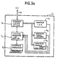
- FIG. 3a represents a first embodiment according to the invention of a central monitoring station for an MLS system.
- all the MLS stations, identified S i are connected to a central station S c using a network of optical fibers FO.
- the signals are received by an optical link interface I F in order to be transformed into electrical signals. They are then directed to a TDM monitor M T , a monitor M D of channel and data and finally a monitor M E , monitoring the angular function signals and the levels emitted by the antennas.
- the results of all the tests carried out by these monitors are sent to a logic control and management unit C L , which is also linked to an operator interface I0 and the optical link interface I F.
- the interface I F comprises a laser diode ensuring the conversion of an electrical signal into an optical signal intended for the FO network, and a photo-diode ensuring the reciprocal conversion; it can also include multiplexing-demultiplexing means.
- the fiber optic network FO can be of any known type, for example in star, ring, or even formed by a set of point-to-point links, each link comprising one or more optical fibers.
- FIG. 3b represents an MLS station S i , adapted to receive the signals transmitted by the central station of FIG. 3a.
- the station S i comprises a transmission means part E and a control part C T.
- the transmission part E is identical to what has been described in FIG. 2, except as regards the control of the sequencer S Q which, here, is carried out not by the synchronization receiver S y (FIG. 2) but by an interface of optical link I F similar to that of FIG. 3a, itself connected to the network of optical fibers FO coming from the central station S c .
- the control part C T is here very simplified since it now only comprises the reception antennas A R , which are connected directly via the interface I F and the optical network FO to the central station S c .
- the assembly constituted by the central station S c (FIG. 3a) and the MLS stations S i (FIG. 3b) operates as follows.
- each of the stations S i Under the control of the central logic unit C L , via the optical network FO, each of the stations S i in turn transmits the MLS signals with which it is responsible.
- the control information provided by the sensors A R of each station S i is sent, via the optical network FO, to the central station S c .
- the signals supplied by each sensor can be multiplexed at the interface I F of each station S i , and demultiplexed in the same way in the central station S c .
- the signals supplied by each sensor can be routed to the central station S c by optical fibers distinct, for example by direct modulation of the light wave emitted by the laser diode; in this case, the control signals are then either multiplexed with the previous ones, or also routed by a separate optical fiber.
- the interface I F of the central station also provides, if necessary, compensation for the differences in propagation time in the optical network FO between the station S c and the different stations S i .
- the reliability of a chain of sub-assemblies is an inverse function of the number of sub-assemblies constituting the chain. More precisely, if the failure rate of a subset i is p i , the probability P of operation of the chain at time t is: For a redundant chain, where the subsets are doubled, we replace e -p i t by (2e -p i t - e 2p i t ).
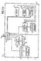
- FIG. 4a represents a second embodiment of a central station for an MLS system according to the invention.
- This station S c has a part E, ensuring the generation of a microwave signal and a part C T , ensuring control.
- the transmission part E comprises a frequency synthesizer F and a phase modulator M similar to those of conventional MLS stations (FIG. 2), which supply a modulated microwave signal, under the control of a sequencer S Q similar to that of FIG. 2. This signal is supplied to the optical interface circuit I F.
- the transmission part E also includes the scanning logic circuit L B , controlled by the sequencer S Q and supplying its control signals to the interface I F.
- the interface I F may include multiplexing-demultiplexing means.
- the network FO is a network of point-to-point links, each link comprising an optical fiber assigned to the transmission signals produced by the emission part E.
- the microwave signal modulated by the modulator M directly modulates the frequency of the optical wave emitted by the laser diode of the interface I F in the optical fiber assigned to the transmission, and the other information to be transmitted are for example multiplexed and transmitted by any means in the remaining bandwidth of the same optical fiber.
- the control part C T includes the same elements as those described in FIG. 3a, except that the logic command and management circuit C L is also connected to the sequencer S Q.
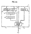
- FIG. 4b represents an MLS station S i adapted to receive the signals transmitted by a central station as shown in FIG. 4a.
- the station S i also includes a transmission part E and a control part C T.
- the control part C T comprises, as previously (FIG. 3b), only the reception antennas A R , connected directly to the interface I F.
- the transmission part E only comprises the microwave amplifier A H , receiving the signal to be amplified from the interface I F and transmitting it to the switch C M , itself controlled by the interface I F and supplying the signal to be transmitted , either to the sectoral antenna A S , or to the electronic scanning antenna A B , or even to the OCI antennas (not shown).
- This second embodiment which integrates all the transmission means, excluding amplification and antennas, into the central station, has various advantages.
- the security of the system is a function of the product reliability of the transmission assembly by reliability of the control assembly. It is therefore increased here by improving the reliability of the two assemblies.
Description
La présente invention se rapporte au domaine des systèmes d'aide à l'atterrissage du type MLS. Elle a plus particulièrement pour objet un système MLS comportant des moyens de surveillance centralisés.The present invention relates to the field of landing aid systems of the MLS type. It more particularly relates to an MLS system comprising centralized monitoring means.
On rappelle que le système MLS (initiales de l'expression anglo-saxonne "Microwave Landing System") est un système permettant de guider un avion à l'atterrissage en lui fournissant différentes informations, appelées "fonctions": des informations angulaires, telles que son angle d'azimut par rapport à l'axe de la piste, son angle de site par rapport à l'horizontale, éventuellement d'autres informations annexes telles que azimut arrière par exemple, et un certain nombre de données, les unes dites "de base" et les autres dites "auxiliaires". Ces différentes informations sont émises en permanence à partir du sol en multiplexage temporel sur une même fréquence, selon des caractéristiques normalisées par l'OACI (Organisation de l'Aviation Civile Internationale), annexe 10 paragraphe III.11. La définition par l'OACI d'un système MLS inclut encore un équipement de mesure de distance, connu sous les initiales DME (de l'expression anglo-saxonne "Distance Measuring Equipment"). Ces informations sont décodées par chaque avion intéressé. Un tel système est décrit par exemple dans le document G. ONODERA et al, NEC research and development, vol.59, octobre 1980, pages 34-35.It is recalled that the MLS system (initials of the Anglo-Saxon expression "Microwave Landing System") is a system making it possible to guide an aircraft on landing by providing it with various information, called "functions": angular information, such as its azimuth angle with respect to the runway axis, its elevation angle with respect to the horizontal, possibly other additional information such as rear azimuth for example, and a certain number of data, some called " basic "and the others called" auxiliary ". This various information is permanently transmitted from the ground in time multiplexing on the same frequency, according to characteristics standardized by the ICAO (International Civil Aviation Organization), Annex 10 paragraph III.11. The ICAO definition of an MLS system also includes distance measurement equipment, known by the initials DME (from the English expression "Distance Measuring Equipment"). This information is decoded by each aircraft concerned. Such a system is described for example in the document G. ONODERA et al, NEC research and development, vol. 59, October 1980, pages 34-35.
Chacune des fonctions précédentes se décompose en deux parties, émises successivement:
- un préambule, dont le rôle est de fournir à l'avion une identification de la fonction qui va suivre; ce préambule est émis par une antenne dite sectorielle, c'est à dire une antenne fixe émettant dans l'ensemble de la zone, ou secteur, que le système MLS doit couvrir; selon la norme OACI, le préambule se présente sous la forme d'un mot de douze bits permettant l'identification de façon bi-univoque de chacune des fonctions; ce mot binaire est émis en modulation de phase de type DPSK (pour "Differential Phase Shift Keying" ou codage de phase différentiel);
- la fonction proprement dite: dans le cas où cette fonction est une donnée, elle est émise par l'antenne sectorielle également en modulation de phase DPSK; dans le cas où cette fonction est une information angulaire, elle est constituée par deux impulsions émises à l'aide d'une antenne à balayage électronique, selon le principe dit du faisceau battant à référence temporelle, qui est notamment décrit dans la demande de brevet français n° 2.549.321 au nom de THOMSON-CSF.
- a preamble, the role of which is to provide the aircraft with an identification of the function which will follow; this preamble is emitted by a so-called sectoral antenna, that is to say a fixed antenna emitting throughout the area, or sector, which the MLS system must cover; according to the ICAO standard, the preamble is in the form of a twelve-bit word allowing the unambiguous identification of each of the functions; this binary word is transmitted in DPSK type phase modulation (for "Differential Phase Shift Keying" or differential phase coding);
- the function itself: in the case where this function is a datum, it is transmitted by the sectoral antenna also in DPSK phase modulation; in the case where this function is angular information, it is constituted by two pulses emitted using an electronic scanning antenna, according to the principle known as the beating beam with time reference, which is notably described in the patent application French n ° 2.549.321 in the name of THOMSON-CSF.
Un système MLS comporte donc au moins autant de stations que de fonctions angulaires à émettre.An MLS system therefore comprises at least as many stations as there are angular functions to be transmitted.
Il apparaît ainsi que les différentes informations nécessaires pour le guidage d'un avion sont émises par des stations distinctes, successivement sur une même fréquence. Il est clair que l'ordre et la durée des émissions doivent être respectés rigoureusement pour que soit assurée la sécurité nécessaire au guidage, surtout lors de l'atterrissage dont on sait qu'il s'agit d'une phase particulièrement délicate. En particulier, tout recouvrement des émissions doit être soigneusement évité. Pour garantir cette sécurité, de nombreux dispositifs ou solutions sont connus et qui prévoient:
- une grande redondance des matériels;
- des liaisons de synchronisation entre les stations, de préférence redondantes elles aussi;
- de nombreuses boucles de surveillance du déroulement des émissions.
- great redundancy of equipment;
- synchronization links between the stations, preferably also redundant;
- numerous monitoring loops for the progress of broadcasts.
Ces différentes solutions tendent à multiplier et compliquer les matériels et les circuits; elles ont notamment le défaut de diminuer la fiabilité de l'ensemble.These different solutions tend to multiply and complicate equipment and circuits; they have in particular failure to reduce the reliability of the assembly.
La présente invention se propose d'augmenter la sécurité d'un système MLS sans en diminuer la fiabilité.The present invention proposes to increase the security of an MLS system without reducing its reliability.
A cet effet, selon l'invention, on centralise les moyens de surveillance des émissions des différentes stations en une même station centrale, qui assure alors la commande des différentes stations MLS, la connexion entre la station centrale et les stations MLS étant assurée par un réseau de fibres optiques.To this end, according to the invention, the means for monitoring the transmissions of the different stations are centralized in the same central station, which then controls the various MLS stations, the connection between the central station and the MLS stations being provided by a fiber optic network.
Plus précisément, l'invention a pour objet un système d'aide à l'atterrissage du type MLS, tel que défini par la revendication 1.More specifically, the subject of the invention is a landing aid system of the MLS type, as defined by claim 1.
Dans une variante de réalisation, les signaux hyperfréquences que doivent émettre les stations MLS sont engendrés également dans la station centrale.In an alternative embodiment, the microwave signals which the MLS stations must transmit are also generated in the central station.
De la sorte, il apparaît que la surveillance des émissions est effectuée dans de meilleures conditions et que le nombre d'équipements est réduit, augmentant ainsi la sécurité et la fiabilité du système, et diminuant son coût.In this way, it appears that the monitoring of the emissions is carried out under better conditions and that the number of devices is reduced, thereby increasing the safety and reliability of the system, and reducing its cost.
D'autres objets, particularités et résultats de l'invention ressortiront de la description suivante, donnée à titre d'exemple non limitatif et illustrée par les dessins annexés, qui représentent:
- la figure 1, un schéma d'implantation d'un système MLS de type connu;
- la figure 2, un schéma synoptique d'une station MLS de type connu;
- les figures 3a et 3b, un premier mode de réalisation selon l'invention respectivement d'une station centrale de surveillance et d'une station MLS qui lui est adaptée;
- les figures 4a et 4b, un deuxième mode de réalisation selon l'invention respectivement d'une station centrale de surveillance et d'une station MLS qui lui est adaptée.
- FIG. 1, a layout diagram of an MLS system of known type;
- FIG. 2, a block diagram of an MLS station of known type;
- Figures 3a and 3b, a first embodiment according to the invention respectively of a central monitoring station and an MLS station which is adapted thereto;
- Figures 4a and 4b, a second embodiment according to the invention respectively of a central monitoring station and an MLS station which is adapted to it.
Sur ces différents figures, les mêmes références se rapportent à des éléments analogues.In these different figures, the same references relate to similar elements.
La figure 1 est donc le schéma d'une implantation classique d'un système MLS.Figure 1 is therefore the diagram of a conventional implementation of an MLS system.
Ce système se compose d'un ensemble de stations MLS disposées autour d'une piste d'atterrissage, repérée P, qui fait habituellement plusieurs kilomètres. Pour un sens donné d'utilisation de la piste P, par exemple le sens D₁, l'information d'angle d'azimut est donnée par une première station A₁, disposée dans l'axe de la piste et à l'autre extrémité de celle-ci par rapport au point d'atterrissage (ou entrée de piste). L'information d'angle de site est donnée par une seconde station, repérée S₁, et disposée près de l'entrée de piste, de préférence latéralement. Dans le cas où on veut disposer d'une information d'azimut arrière, le système comporte une troisième station, repérée A₂, et disposée dans l'axe de la piste côté entrée de piste. Lorsque la piste peut être utilisée dans l'autre sens (flèche D₂), le système comprend un second ensemble de deux stations, azimut et site respectivement; la station azimut pour le sens D₂ peut être la même station A₂ que celle qui fournit l'information d'azimut arrière pour le sens D₁; l'information de site pour le sens D₂ sera donnée par une quatrième station, repérée S₂, disposée au voisinage de l'entrée de piste dans le sens D₂, de la même manière que la station S₁. En outre, un équipement de mesure de distance DME est nécessaire pour chaque sens de piste; il est en général disposé dans la station azimut (A₁ et A₂), sans que cela soit nécessaire. Un tel équipement DME est par exemple décrit dans la demande de brevet français n° 2.576.111 au nom de THOMSON-CSF.This system consists of a set of MLS stations arranged around an airstrip, marked P, which is usually several kilometers long. For a given direction of use of the track P, for example the direction D₁, the azimuth angle information is given by a first station A₁, arranged in the axis of the track and at the other end of this in relation to the landing point (or runway entry). The site angle information is given by a second station, marked S₁, and arranged near the runway entrance, preferably laterally. In the case where it is desired to have rear azimuth information, the system comprises a third station, marked A₂, and arranged in the axis of the runway on the runway entry side. When the track can be used in the other direction (arrow D₂), the system comprises a second set of two stations, azimuth and site respectively; the azimuth station for the direction D₂ may be the same station A₂ as that which supplies the rear azimuth information for the direction D₁; the site information for direction D₂ will be given by a fourth station, marked S₂, arranged in the vicinity of the runway entrance in direction D₂, in the same way as station S₁. In addition, DME distance measuring equipment is required for each runway direction; it is generally placed in the azimuth station (A₁ and A₂), without this being necessary. Such DME equipment is for example described in French patent application No. 2,576,111 in the name of THOMSON-CSF.
Afin d'éviter le recouvrement des émissions de ces différentes stations, toutes les stations susceptibles de travailler pour un sens de piste donné sont reliées entre elles par des liaisons de synchronisation, représentées sur la figure en pointillés et reperées Ls.In order to avoid overlapping of the emissions of these different stations, all the stations likely to work for a given runway direction are linked together by synchronization links, shown in the dotted figure and marked L s .
En outre, ces différentes stations sont reliées à une salle technique T par des liaisons Lc repérées en pointillés et permettant à un opérateur de télécommander le fonctionnement des stations et d'en recevoir des compte-rendus (états détaillés).In addition, these different stations are linked to a technical room T by links L c marked with dotted lines and allowing an operator to remotely control the operation of the stations and to receive reports (detailed reports).
La figure 2 est un schéma synoptique d'une station MLS de type connu.Figure 2 is a block diagram of an MLS station of known type.
Une telle station est chargée d'émettre l'une des fonctions MLS (azimut, site, azimut arrière...) ; elle est repérée Si et représente l'une des stations MLS de la figure 1 (S₁, S₂, A₁ ou A₂).Such a station is responsible for transmitting one of the MLS functions (azimuth, site, rear azimuth ...); it is marked S i and represents one of the MLS stations of FIG. 1 (S₁, S₂, A₁ or A₂).
Cette station Si comporte essentiellement deux parties, une partie située à gauche de la figure et repérée E, comportant les moyens d'émission de la station, et une partie située à droite et repérée CT, comportant les moyens de contrôle du fonctionnement de la station.This station S i essentially comprises two parts, a part situated on the left of the figure and marked E, comprising the transmitting means of the station, and a part situated on the right and marked C T , comprising the means of controlling the operation of the station.
La partie émetteur E comporte, en cascade:
- un synthétiseur de fréquences F, fournissant un signal sinusoïdal destiné à former une onde porteuse, dont la fréquence est voisine de 5 GHz selon la norme OACI (on rappelle que, selon cette norme, une fréquence, ou canal, parmi 200 fréquences prédéfinies, voisines de 5 GHz, est affectée à chaque système MLS);
- un modulateur M du signal fourni par synthétiseur F, qui réalise une modulation de phase DPSK à deux états, permettant d'émettre le préambule et les données;
- un amplificateur hyperfréquence AH, réalisé à l'aide de tubes ou de transistors selon la puissance requise; celle-ci est classiquement de l'ordre de 20 Watts et donc, le plus souvent, l'amplificateur est réalisé à l'aide de transistors;
- un commutateur CM, relié à la fois à une antenne sectorielle As, à une antenne à balayage électronique AB et éventuellement, à des antennes (non représentées) dites OCI (pour Out of Coverage Indicator ou indicateur de situation hors couverture), ayant pour fonction d'indiquer à l'avion que, étant en dehors de la couverture du système MLS, il ne doit pas prendre en compte les signaux qu'il reçoit; le commutateur CM est chargé de commuter le signal produit par la chaîne précédente vers l'une des antennes.
- a frequency synthesizer F, providing a sinusoidal signal intended to form a carrier wave, the frequency of which is close to 5 GHz according to the ICAO standard (it is recalled that, according to this standard, one frequency, or channel, among 200 predefined, neighboring frequencies 5 GHz, is assigned to each MLS system);
- a modulator M of the signal supplied by synthesizer F, which performs a DPSK phase modulation with two states, making it possible to transmit the preamble and the data;
- a microwave amplifier A H , produced using tubes or transistors according to the required power; this is conventionally of the order of 20 Watts and therefore, most often, the amplifier is produced using transistors;
- a switch C M , connected both to a sectoral antenna A s , to an electronic scanning antenna A B and possibly to antennas (not shown) called OCI (for Out of Coverage Indicator), whose function is to indicate to the aircraft that, being outside the coverage of the MLS system, it must not take into account the signals it receives; the switch C M is responsible for switching the signal produced by the previous chain to one of the antennas.
Les moyens d'émission E comportent encore un séquenceur SQ, assurant la commande des éléments F, M, AH et CM, ainsi que celle de l'antenne à balayage électronique AB par l'intermédiaire d'un circuit logique de balayage LB.The transmission means E also comprise a sequencer S Q , ensuring the control of the elements F, M, A H and C M , as well as that of the electronic scanning antenna A B via a logic circuit of scan L B.
De la sorte et sous la commande du séquenceur SQ, les moyens d'émission F à AH fournissent un signal, par l'intermédiaire du commutateur CM, soit à l'antenne sectorielle As pour l'émission du préambule et des données, soit à l'antenne à balayage électronique AB pour l'émission de l'information angulaire, soit aux antennes OCI pour les indications de situation hors couverture.In this way and under the control of the sequencer S Q , the transmission means F to A H supply a signal, via the switch C M , or to the sector antenna A s for the transmission of the preamble and data, either to the electronic scanning antenna A B for the transmission of the angular information, or to the OCI antennas for the indications of situation out of coverage.
La partie contrôle CT de la station MLS comporte:
- un ensemble d'antennes de réception AR, ou capteurs, pour recevoir le signal tel qu'émis par la station Si; cet ensemble peut comporter un capteur externe, par exemple du type cornet, analogue au récepteur porté par les avions guidés, placé à quelques dizaines de mètres des antennes; il peut comporter également un dispositif de prélèvement du signal situé au niveau de chacune des antennes elles-mêmes, connu sous le nom de moniteur intégral;
- un ensemble de trois moniteurs: ME, MD et MT, ayant chacun pour fonction d'effectuer des tests prédéfinis sur les informations qu'ils reçoivent des antennes de réception AR, c'est-à-dire d'effectuer des mesures sur ces informations et de les comparer à des valeurs de référence qu'ils ont en mémoire; lorsque les différences entre les résultats des mesures et les valeurs de référence excèdent des limites prédéfinies, les moniteurs, chacun pour les données qui les concernent, fournissent un signal d'alarme; le moniteur ME est chargé de la surveillance des niveaux des signaux émis par les antennes et de la position des impulsions correspondant aux informations angulaires; le moniteur MD est chargé de surveiller la fréquence d'émission qui doit, on le rappelle, correspondre à un canal MLS prédéterminé, ainsi que les préambules et les données émis par l'antenne sectorielle; le moniteur MT, dit moniteur TDM, est chargé de surveiller le multiplexage dans le temps des différentes informations MLS;
- des circuits logiques CL de commande et de gestion, en général constitués par un microprocesseur, recevant les signaux des différents moniteurs et commandant en conséquence l'arrêt-marche de la station par l'intermédiaire d'un ou plusieurs parmi les éléments F, M, AH, CM et SQ.
- a set of reception antennas A R , or sensors, for receiving the signal as transmitted by the station S i ; this assembly may include an external sensor, for example of the horn type, analogous to the receiver carried by guided planes, placed a few tens of meters from the antennas; it can also include a signal sampling device located at the level of each of the antennas themselves, known as an integral monitor;
- a set of three monitors: M E , M D and M T , each having the function of carrying out predefined tests on the information they receive from the reception antennas A R , that is to say performing measurements on this information and compare it to reference values they have in memory; when the differences between the results of the measurements and the reference values exceed predefined limits, the monitors, each for the data which concern them, provide an alarm signal; the monitor M E is responsible for monitoring the levels of the signals emitted by the antennas and the position of the pulses corresponding to the angular information; the monitor M D is responsible for monitoring the transmission frequency which must, it will be recalled, correspond to a predetermined MLS channel, as well as the preambles and the data transmitted by the sectoral antenna; the monitor M T , called the TDM monitor, is responsible for monitoring the time multiplexing of the various MLS information;
- logic circuits C L for control and management, generally constituted by a microprocessor, receiving the signals from the various monitors and consequently controlling the stop-start of the station via one or more of the elements F, M, A H , C M and S Q.
La partie contrôle comporte encore des moyens d'interface I₀ avec un opérateur, reliés aux circuits logiques de commande CL et susceptibles d'échanger ordres télécommandés et compte-rendus avec la salle technique T (figure 1).The control part also comprises interface means I₀ with an operator, connected to the logic control circuits C L and capable of exchanging remote-controlled orders and reports with the technical room T (FIG. 1).
La station décrite ici est composée d'une chaîne d'émission unique. Pour des raisons de disponibilité, de sécurité ou de fiabilité, elle peut bien entendu être doublée. Ceci conduit à la création d'une deuxième chaîne E et à la modification corrélative des moyens assurant les fonctions de contrôle, de commande et de gestion.The station described here is made up of a single broadcast channel. For reasons of availability, security or reliability, it can of course be doubled. This leads to the creation of a second chain E and to the corresponding modification of the means ensuring the functions of control, command and management.
La station Si comporte encore un circuit Sy d'émission et de réception des informations de synchronisation véhiculées par les liaisons LS et en provenance des autres stations Si du système MLS. Afin d'assurer la synchronisation entre les stations Si, une des solutions possibles est que chacune des stations envoie à la station qui la suit dans l'ordre des émissions une (ou plusieurs) impulsion de synchronisation, sur commande de l'unité logique CL et via le circuit Sy et la liaison Ls; la réception de cette impulsion par le circuit Sy de la station concernée, éventuellement après un retard prédéfini, déclenche l'émission par l'intermédiaire du séquenceur SQ; elle peut déclencher également l'envoi d'un accusé de réception vers la station ayant émis l'impulsion de synchronisation. Plus généralement, la synchronisation a pour but d'assurer le séquencement des émissions selon les normes OACI, à l'aide d'échanges d'ordres et de compte-rendus sur le réseau de liaisons Ls. Par ailleurs, le moniteur MT assure la surveillance du multiplexage sur la base des informations qu'il reçoit du circuit Sy et de sa propre station.The station S i also includes a circuit S y for transmitting and receiving the synchronization information conveyed by the links L S and coming from the other stations S i of the MLS system. In order to ensure synchronization between the stations S i , one of the possible solutions is that each of the stations sends to the station which follows it in the order of the transmissions one (or more) synchronization pulse, on command of the logic unit. C L and via the circuit S y and the link L s ; the reception of this pulse by the circuit S y of the station concerned, possibly after a predefined delay, triggers the transmission via the S Q sequencer; it can also trigger the sending of an acknowledgment to the station that sent the synchronization pulse. More generally, the purpose of synchronization is to ensure the sequencing of emissions according to the ICAO standards, using exchanges of orders and reports on the L s link network. Furthermore, the monitor M T monitors the multiplexing on the basis of the information it receives from the circuit S y and from its own station.
Il apparaît ainsi que le non-recouvrement des différentes émissions MLS repose entièrement sur la réception d'impulsions de synchronisation, avec le risque inhérent à ce type de procédé.It thus appears that the non-recovery of the various MLS transmissions is entirely based on the reception of synchronization pulses, with the risk inherent in this type of process.
La figure 3a représente un premier mode de réalisation selon l'invention d'une station centrale de surveillance pour un système MLS.FIG. 3a represents a first embodiment according to the invention of a central monitoring station for an MLS system.
Selon l'invention, l'ensemble des stations MLS, repérées Si, sont reliées à une station centrale Sc à l'aide d'un réseau de fibres optiques FO.According to the invention, all the MLS stations, identified S i , are connected to a central station S c using a network of optical fibers FO.
Dans la station centrale (Sc), les signaux sont reçus par une interface de liaison optique IF afin d'être transformés en signaux électriques. Ils sont ensuite dirigés vers un moniteur TDM MT, un moniteur MD de canal et de donnée et enfin un moniteur ME, surveillant les signaux de fonction angulaire et les niveaux émis par les antennes. Les résultats de l'ensemble des tests effectués par ces moniteurs sont adressés à une unité logique de commande et de gestion CL, qui est par ailleurs en liaison avec une interface opérateur I₀ et l'interface de liaison optique IF.In the central station (S c ), the signals are received by an optical link interface I F in order to be transformed into electrical signals. They are then directed to a TDM monitor M T , a monitor M D of channel and data and finally a monitor M E , monitoring the angular function signals and the levels emitted by the antennas. The results of all the tests carried out by these monitors are sent to a logic control and management unit C L , which is also linked to an operator interface I₀ and the optical link interface I F.
Typiquement, l'interface IF comporte une diode laser assurant la conversion d'un signal électrique en un signal optique à destination du réseau FO, et une photo-diode assurant la conversion réciproque; elle peut en outre comporter des moyens de multiplexage-démultiplexage. Le réseau de fibres optiques FO peut être de tout type connu, par exemple en étoile, en anneau, ou encore formé par un ensemble de liaisons point à point, chaque liaison comportant une ou plusieurs fibres optiques.Typically, the interface I F comprises a laser diode ensuring the conversion of an electrical signal into an optical signal intended for the FO network, and a photo-diode ensuring the reciprocal conversion; it can also include multiplexing-demultiplexing means. The fiber optic network FO can be of any known type, for example in star, ring, or even formed by a set of point-to-point links, each link comprising one or more optical fibers.
La figure 3b représente une station MLS Si, adaptée pour recevoir les signaux émis par la station centrale de la figure 3a.FIG. 3b represents an MLS station S i , adapted to receive the signals transmitted by the central station of FIG. 3a.
Comme précédemment (figure 2), la station Si comporte une partie moyens d'émission E et une partie contrôle CT.As before (FIG. 2), the station S i comprises a transmission means part E and a control part C T.
La partie émission E est identique à ce qui a été décrit figure 2, sauf en ce qui concerne la commande du séquenceur SQ qui, ici, est effectuée non pas par le récepteur de synchronisation Sy (figure 2) mais par une interface de liaison optique IF analogue à celle de la figure 3a, elle-même reliée au réseau de fibres optiques FO en provenance de la station centrale Sc.The transmission part E is identical to what has been described in FIG. 2, except as regards the control of the sequencer S Q which, here, is carried out not by the synchronization receiver S y (FIG. 2) but by an interface of optical link I F similar to that of FIG. 3a, itself connected to the network of optical fibers FO coming from the central station S c .
La partie contrôle CT est ici très simplifiée puisqu'elle ne comporte plus que les antennes de réception AR, qui sont reliées directement via l'interface IF et le réseau optique FO à la station centrale Sc.The control part C T is here very simplified since it now only comprises the reception antennas A R , which are connected directly via the interface I F and the optical network FO to the central station S c .
L'ensemble constitué par la station centrale Sc (figure 3a) et les stations MLS Si (figure 3b) fonctionne de la façon suivante.The assembly constituted by the central station S c (FIG. 3a) and the MLS stations S i (FIG. 3b) operates as follows.
Sous la commande de l'unité logique centrale CL, via le réseau optique FO, chacune des stations Si émet à son tour les signaux MLS dont elle est chargée.Under the control of the central logic unit C L , via the optical network FO, each of the stations S i in turn transmits the MLS signals with which it is responsible.
Les informations de contrôle fournies par les capteurs AR de chaque station Si sont adressées, via le réseau optique FO, à la station centrale Sc. A cet effet, les signaux fournis par chaque capteur peuvent être multiplexés au niveau de l'interface IF de chaque station Si, et démultiplexés de la même manière dans la station centrale Sc. Selon un autre mode de réalisation, les signaux fournis par chaque capteur peuvent être acheminés vers la station centrale Sc par des fibres optiques distinctes, par exemple par modulation directe de l'onde lumineuse émise par la diode laser ; dans ce cas, les signaux de commande sont alors soit multiplexés avec les précédents, soit acheminés également par une fibre optique distincte.The control information provided by the sensors A R of each station S i is sent, via the optical network FO, to the central station S c . To this end, the signals supplied by each sensor can be multiplexed at the interface I F of each station S i , and demultiplexed in the same way in the central station S c . According to another embodiment, the signals supplied by each sensor can be routed to the central station S c by optical fibers distinct, for example by direct modulation of the light wave emitted by the laser diode; in this case, the control signals are then either multiplexed with the previous ones, or also routed by a separate optical fiber.
Il est à noter que l'interface IF de la station centrale assure en outre, le cas échéant, la compensation des différences de temps de propagation dans le réseau optique FO entre la station Sc et les différentes stations Si.It should be noted that the interface I F of the central station also provides, if necessary, compensation for the differences in propagation time in the optical network FO between the station S c and the different stations S i .
Il est ainsi recréé dans la station centrale Sc le multiplexage temporel des différents signaux MLS tel qu'il est reçu par l'avion à guider. Il en résulte que le contrôle est effectué dans de meilleures conditions puisque plus proches des conditions réelles que dans le système classique tel que décrit figures 1 et 2.It is thus recreated in the central station S c the time multiplexing of the various MLS signals as received by the aircraft to be guided. As a result, the control is carried out under better conditions since they are closer to real conditions than in the conventional system as described in FIGS. 1 and 2.
De plus, cet accroissement de sécurité ne se fait pas par accroissement de la complexité du système mais, au contraire, s'accompagne d'une réduction du nombre de circuits nécessaires, à redondance donnée : en effet, les éléments sont désormais en un seul exemplaire dans la station centrale Sc et non plus multipliés en autant d'exemplaires que de stations MLS Si.In addition, this increase in security is not achieved by increasing the complexity of the system but, on the contrary, is accompanied by a reduction in the number of circuits required, with given redundancy: indeed, the elements are now in one copy in central station S c and no longer multiplied by as many copies as in MLS stations S i .
Une conséquence en est une augmentation de la fiabilité. On sait en effet que la fiabilité d'une chaîne de sous-ensembles est une fonction inverse du nombre de sous-ensembles constituant la chaîne. Plus précisément, si le taux de panne d'un sous-ensemble i est pi, la probabilité P de fonctionnement de la chaîne à l'instant t est:![]()
Pour une chaîne redondante, où les sous-ensembles sont doublés, on remplace e -pit par (2e-pit - e2pit).One consequence is an increase in reliability. We know that the reliability of a chain of sub-assemblies is an inverse function of the number of sub-assemblies constituting the chain. More precisely, if the failure rate of a subset i is p i , the probability P of operation of the chain at time t is: ![]()
For a redundant chain, where the subsets are doubled, we replace e -p i t by (2e -p i t - e 2p i t ).
Par ailleurs, la sécurité du système dépend également du risque de rayonner un signal erroné, donc dangereux. La probabilité PR de rayonner un tel signal est le produit :![]()
où :
- Pem est la probabilité de panne de l'ensemble d'émission (en se limitant au cas d'un signal dangereux); elle est une fonction inverse de la fiabilité de l'ensemble d'émission;
- Ppe est la probabilité qu'une panne ne soit pas vue par l'ensemble de contrôle (panne cachée de l'ensemble de contrôle); elle est une fonction inverse de la fiabilité de l'ensemble de contrôle.
Il en résulte que la sécurité est une fonction du produit fiabilité de l'ensemble d'émission par fiabilité de l'ensemble de contrôle. Elle se trouve donc augmentée par l'amélioration de la fiabilité de l'ensemble de contrôle.Furthermore, the security of the system also depends on the risk of radiating an erroneous and therefore dangerous signal. The probability P R of radiating such a signal is the product:
or :
- P em is the probability of failure of the transmission assembly (limited to the case of a dangerous signal); it is an inverse function of the reliability of the transmission assembly;
- P pe is the probability that a failure is not seen by the control assembly (hidden failure of the control assembly); it is an inverse function of the reliability of the control assembly.
As a result, security is a function of the product reliability of the transmission assembly by reliability of the control assembly. It is therefore increased by improving the reliability of the control assembly.
Enfin, une autre conséquence de la réduction du nombre de circuits est bien entendu une réduction du coût du système.Finally, another consequence of the reduction in the number of circuits is of course a reduction in the cost of the system.
La figure 4a représente un deuxième mode de réalisation d'une station centrale pour un système MLS selon l'invention.FIG. 4a represents a second embodiment of a central station for an MLS system according to the invention.
Cette station Sc comporte une partie E, assurant la génération d'un signal hyperfréquence et une partie CT, en assurant le contrôle.This station S c has a part E, ensuring the generation of a microwave signal and a part C T , ensuring control.
La partie émission E comporte un synthétiseur de fréquence F et un modulateur de phase M analogues à ceux des stations MLS classiques (figure 2), qui fournissent un signal hyperfréquence modulé, sous la commande d'un séquenceur SQ analogue à celui de la figure 2. Ce signal est fourni au circuit d'interface optique IF. La partie émission E comporte encore le circuit de logique de balayage LB, commandé par le séquenceur SQ et fournissant ses signaux de commande à l'interface IF. Comme précédemment, l'interface IF peut comporter des moyens de multiplexage-démultiplexage. Dans un mode de réalisation, le réseau FO est un réseau de liaisons point à point, chaque liaison comportant une fibre optique affectée à la transmission des signaux produits par la partie émission E. Dans ce cas, le signal hyperfréquence modulé par le modulateur M vient moduler directement la fréquence de l'onde optique émise par la diode laser de l'interface IF dans la fibre optique affectée à l'émission, et les autres informations à transmettre sont par exemple multiplexées et transmises par tout moyen dans la bande passante restante de la même fibre optique.The transmission part E comprises a frequency synthesizer F and a phase modulator M similar to those of conventional MLS stations (FIG. 2), which supply a modulated microwave signal, under the control of a sequencer S Q similar to that of FIG. 2. This signal is supplied to the optical interface circuit I F. The transmission part E also includes the scanning logic circuit L B , controlled by the sequencer S Q and supplying its control signals to the interface I F. As before, the interface I F may include multiplexing-demultiplexing means. In one embodiment, the network FO is a network of point-to-point links, each link comprising an optical fiber assigned to the transmission signals produced by the emission part E. In this case, the microwave signal modulated by the modulator M directly modulates the frequency of the optical wave emitted by the laser diode of the interface I F in the optical fiber assigned to the transmission, and the other information to be transmitted are for example multiplexed and transmitted by any means in the remaining bandwidth of the same optical fiber.
La partie contrôle CT comporte les mêmes éléments que ceux qui sont décrits figure 3a, à ceci près que le circuit logique de commande et de gestion CL est en outre relié au séquenceur SQ.The control part C T includes the same elements as those described in FIG. 3a, except that the logic command and management circuit C L is also connected to the sequencer S Q.
La figure 4b représente une station MLS Si adaptée pour recevoir les signaux émis par une station centrale telle que représentée sur la figure 4a.FIG. 4b represents an MLS station S i adapted to receive the signals transmitted by a central station as shown in FIG. 4a.
La station Si comporte également une partie émission E et une partie contrôle CT.The station S i also includes a transmission part E and a control part C T.
La partie contrôle CT comporte comme précédemment (figure 3b) uniquement les antennes de réception AR, reliées directement à l'interface IF.The control part C T comprises, as previously (FIG. 3b), only the reception antennas A R , connected directly to the interface I F.
La partie émission E ne comporte plus que l'amplificateur hyperfréquence AH, recevant le signal à amplifier de l'interface IF et le transmettant au commutateur CM, lui-même commandé par l'interface IF et fournissant le signal à émettre, soit à l'antenne sectorielle AS, soit à l'antenne à balayage électronique AB, soit encore aux antennes OCI (non représentées).The transmission part E only comprises the microwave amplifier A H , receiving the signal to be amplified from the interface I F and transmitting it to the switch C M , itself controlled by the interface I F and supplying the signal to be transmitted , either to the sectoral antenna A S , or to the electronic scanning antenna A B , or even to the OCI antennas (not shown).
Ce deuxième mode de réalisation, qui intègre à la station centrale tous les moyens d'émission, hors amplification et antennes, présente différents avantages.This second embodiment, which integrates all the transmission means, excluding amplification and antennas, into the central station, has various advantages.
Tout d'abord, il permet d'accentuer les effets précédemment décrits de réduction de matériel et d'accroissement de sécurité et de fiabilité.First of all, it makes it possible to accentuate the previously described effects of reduction of material and increase of safety and reliability.
Notamment, comme mentionné plus haut, la sécurité du système est une fonction du produit fiabilité de l'ensemble d'émission par fiabilité de l'ensemble de contrôle. Elle se trouve donc augmentée ici par l'amélioration de la fiabilité des deux ensembles.In particular, as mentioned above, the security of the system is a function of the product reliability of the transmission assembly by reliability of the control assembly. It is therefore increased here by improving the reliability of the two assemblies.
De plus, tous les signaux étant ici engendrés séquentiellement en un même point, la synchronisation des différentes émissions est effectuée automatiquement, le moniteur TDM MT de la station centrale n'ayant plus qu'à vérifier le bon fonctionnement de la partie émission E de cette station. La sécurité du système s'en trouve ainsi encore grandement améliorée.In addition, all the signals here being generated sequentially at the same point, the synchronization of the various transmissions is carried out automatically, the TDM monitor M T of the central station having only to verify the proper functioning of the transmission part E of this station. System security is thus greatly improved.
Claims (4)
- Landing aid system of the MLS type, consisting of transmitting, towards an aircraft, in time-division multiplexing on the same carrier frequency, information known as functions, successively comprising a preamble and either data or angular information, the system including at least two MLS stations (Si) which each include:- a sector antenna (As), carrying out transmission of the preambles and of the data, in the form of the phase modulated carrier wave;- an electronic-scanning antenna (AB), carrying out transmission of the angular information, in the form of scans of a beam of the wave at the carrier frequency;- means (CT) for checking the operation of the station;the system being characterized in that it further includes a central station (Sc), including specific checking means (CT), linked to the means for checking the MLS stations (Si) by at least one optical fibre (FO), and means (IF) for an interface of the optical fibre with the checking means;
in that the checking means (CT) specific to the central station (Sc) include:- first monitor means (MT) carrying out checking of the time-division multiplexing of the MLS functions, which are linked to the interface means (IF);- second monitor means (MD) carrying out checking of the carrier frequency and of the data, linked to the interface means (IF);- third monitor means (ME) carrying out checking of the angular information and of the level of the transmitted signals, linked to the interface means (IF);- logic means (CL) for control and management of the central station and of the MLS stations, linked to all of the specific checking means and to the interface means (IF);and in that each of the MLS stations (Si) includes means (IF) for interface of the optical fibre (FO) with its own checking means (CT), the latter including at least one receiving antenna (AR) for the signals transmitted by the station, supplying these received signals to the interface means (IF), which signals are destined for the central station (Sc). - System according to Claim 1, characterized in that each of the MLS stations (Si) includes transmission means (E), the latter including:- means (F) for generating a signal at the carrier frequency;- means (M) for modulating the preceding signal by the preambles and the data;- means (AH) for amplifying the signals received from the modulation means;- a changeover switch (CM) carrying out changeover switching of the amplified signals between the sector and antenna (As) and the electronic-scanning antenna (AB)
- System according to Claim 1, characterized in that the central station (Sc) further includes transmission means (E), the latter including:- means (F) for generating a signal at the carrier frequency;- means (M) for modulating the preceding signal by the preambles and the data, supplying the modulated signal to the interface means (IF), which signals are destined for the MLS stations (Si).
- System according to Claim 3, characterized in that each of the MLS stations (Si) includes transmission means (E), the latter including:- means (AH) for amplifying the signals received from the central station (Sc) via the interface means (IF);- a changeover switch (CM) carrying out changeover switching of the amplified signals between the sector antenna (As) and the electronic-scanning antenna (AB).
Applications Claiming Priority (2)
| Application Number | Priority Date | Filing Date | Title |
|---|---|---|---|
| FR8916617 | 1989-12-15 | ||
| FR8916617A FR2656135B1 (en) | 1989-12-15 | 1989-12-15 | MLS TYPE LANDING ASSISTANCE SYSTEM COMPRISING CENTRALIZED SURVEILLANCE MEANS. |
Publications (2)
| Publication Number | Publication Date |
|---|---|
| EP0433162A1 EP0433162A1 (en) | 1991-06-19 |
| EP0433162B1 true EP0433162B1 (en) | 1994-08-03 |
Family
ID=9388556
Family Applications (1)
| Application Number | Title | Priority Date | Filing Date |
|---|---|---|---|
| EP90403525A Expired - Lifetime EP0433162B1 (en) | 1989-12-15 | 1990-12-11 | MLS type landing aid system, having centralized means for microwave generation |
Country Status (6)
| Country | Link |
|---|---|
| US (1) | US5101207A (en) |
| EP (1) | EP0433162B1 (en) |
| JP (1) | JPH06274800A (en) |
| CA (1) | CA2032074A1 (en) |
| DE (1) | DE69011296T2 (en) |
| FR (1) | FR2656135B1 (en) |
Families Citing this family (1)
| Publication number | Priority date | Publication date | Assignee | Title |
|---|---|---|---|---|
| AU7117794A (en) * | 1993-06-17 | 1995-01-17 | Canadian Space Agency | System and method for modulating a carrier frequency |
Family Cites Families (5)
| Publication number | Priority date | Publication date | Assignee | Title |
|---|---|---|---|---|
| US3820074A (en) * | 1971-12-06 | 1974-06-25 | Tull Aviation Corp | Remote operating condition data acquisition system |
| FR2518759A1 (en) * | 1981-12-18 | 1983-06-24 | Thomson Csf | MICROWAVE LANDING SYSTEM WITH SEPARATE SITE AND AZIMUTH STATIONS |
| US4814773A (en) * | 1983-05-11 | 1989-03-21 | Hughes Aircraft Company | Fiber optic feed network for radar |
| FR2574946B1 (en) * | 1984-12-14 | 1987-01-30 | Thomson Csf | METHOD FOR RADIOELECTRIC SYNCHRONIZATION OF SLAVE STATIONS BY A MASTER STATION, PARTICULARLY FOR AN MLS LANDING ASSISTANCE SYSTEM, AND DEVICES FOR IMPLEMENTING SUCH A METHOD |
| FR2582127B1 (en) * | 1985-03-29 | 1994-05-20 | Thomson Csf | METHOD AND DEVICE FOR MONITORING A STATION OF AN MLS TYPE LANDING AID SYSTEM |
-
1989
- 1989-12-15 FR FR8916617A patent/FR2656135B1/en not_active Expired - Fee Related
-
1990
- 1990-12-11 DE DE69011296T patent/DE69011296T2/en not_active Expired - Fee Related
- 1990-12-11 EP EP90403525A patent/EP0433162B1/en not_active Expired - Lifetime
- 1990-12-12 US US07/626,544 patent/US5101207A/en not_active Expired - Fee Related
- 1990-12-12 CA CA002032074A patent/CA2032074A1/en not_active Abandoned
- 1990-12-15 JP JP2410805A patent/JPH06274800A/en not_active Withdrawn
Also Published As
| Publication number | Publication date |
|---|---|
| CA2032074A1 (en) | 1991-06-16 |
| FR2656135A1 (en) | 1991-06-21 |
| US5101207A (en) | 1992-03-31 |
| JPH06274800A (en) | 1994-09-30 |
| FR2656135B1 (en) | 1994-08-26 |
| DE69011296D1 (en) | 1994-09-08 |
| EP0433162A1 (en) | 1991-06-19 |
| DE69011296T2 (en) | 1995-03-02 |
Similar Documents
| Publication | Publication Date | Title |
|---|---|---|
| CA1245753A (en) | Method and device for monitoring a mls station | |
| EP0505284A1 (en) | Satellite telecommunication installation applicable to several coverage zones | |
| EP3665744B1 (en) | Device for optically receiving a signal coming from a phased antenna array and associated antenna system | |
| EP0231015B1 (en) | Coherent photonic telecommunication device | |
| EP0433161B1 (en) | MLS type landing aid system, having centralized means for microwave generation | |
| CA1283972C (en) | Adaptive antenne system for radio waves, especially microwaves | |
| FR2548467A1 (en) | NETWORK ANTENNA RADAR CONTROLLED IN PHASE A OPTICAL ADJUSTMENT | |
| EP0433162B1 (en) | MLS type landing aid system, having centralized means for microwave generation | |
| EP2363729A1 (en) | Channel formatter that can be reconfigured for an array antenna | |
| EP2260540B1 (en) | Optical device for applying a real delay to a radio-electric signal and application in the formation of transmission and reception beams with an active antenna | |
| EP0964476B1 (en) | Wideband radar optical control device for receiving or transmitting | |
| EP0381102B1 (en) | Fibre-optical communication network with frequency division multiplexing | |
| FR2518759A1 (en) | MICROWAVE LANDING SYSTEM WITH SEPARATE SITE AND AZIMUTH STATIONS | |
| EP0128800B1 (en) | Optical quadripole and multipole comprised of such a quadripole | |
| FR2810745A1 (en) | SPATIAL POLLUTION MEASURING DEVICE | |
| EP0188937B1 (en) | Method for the radio-electric synchronization of slave stations with a master station, particularly for an mls landing system, and devices for carrying out such a method | |
| EP0083534B1 (en) | Mls with interference protection | |
| FR2681143A1 (en) | IFF method of identification protected against interference and system for implementing it | |
| EP0282399B1 (en) | Base station receiving system for optically transmitted data issued from n mobile stations | |
| EP0401126B1 (en) | Self-heterodyning optical signal transmission method and transmission system with switching matrix implementing the method | |
| EP0191657A1 (en) | Method for radioelectrically synchronizing stations of an MLS landing aid system by a DME station, and devices for carrying out such a method | |
| CN113721221A (en) | Frequency modulation continuous wave laser radar | |
| FR3139258A1 (en) | OPTICAL TERMINAL FOR COMMUNICATION BY LASER SIGNALS | |
| FR2672168A1 (en) | METHOD AND DEVICE FOR RELATIVE POSITIONING OF FREQUENCY, IN PARTICULAR OPTICAL. | |
| FR2718307A1 (en) | Full-duplex data transmission method e.g. for optical, radio transmission |
Legal Events
| Date | Code | Title | Description |
|---|---|---|---|
| PUAI | Public reference made under article 153(3) epc to a published international application that has entered the european phase |
Free format text: ORIGINAL CODE: 0009012 |
|
| AK | Designated contracting states |
Kind code of ref document: A1 Designated state(s): CH DE GB IT LI |
|
| 17P | Request for examination filed |
Effective date: 19911123 |
|
| RAP1 | Party data changed (applicant data changed or rights of an application transferred) |
Owner name: THOMSON-CSF |
|
| 17Q | First examination report despatched |
Effective date: 19940110 |
|
| GRAA | (expected) grant |
Free format text: ORIGINAL CODE: 0009210 |
|
| AK | Designated contracting states |
Kind code of ref document: B1 Designated state(s): CH DE GB IT LI |
|
| ITF | It: translation for a ep patent filed |
Owner name: JACOBACCI CASETTA & PERANI S.P.A. |
|
| REF | Corresponds to: |
Ref document number: 69011296 Country of ref document: DE Date of ref document: 19940908 |
|
| GBT | Gb: translation of ep patent filed (gb section 77(6)(a)/1977) |
Effective date: 19941011 |
|
| PGFP | Annual fee paid to national office [announced via postgrant information from national office to epo] |
Ref country code: CH Payment date: 19941118 Year of fee payment: 5 |
|
| PLBE | No opposition filed within time limit |
Free format text: ORIGINAL CODE: 0009261 |
|
| STAA | Information on the status of an ep patent application or granted ep patent |
Free format text: STATUS: NO OPPOSITION FILED WITHIN TIME LIMIT |
|
| 26N | No opposition filed | ||
| PG25 | Lapsed in a contracting state [announced via postgrant information from national office to epo] |
Ref country code: LI Effective date: 19951231 Ref country code: CH Effective date: 19951231 |
|
| REG | Reference to a national code |
Ref country code: CH Ref legal event code: PL |
|
| PGFP | Annual fee paid to national office [announced via postgrant information from national office to epo] |
Ref country code: DE Payment date: 19981116 Year of fee payment: 9 |
|
| PGFP | Annual fee paid to national office [announced via postgrant information from national office to epo] |
Ref country code: GB Payment date: 19981118 Year of fee payment: 9 |
|
| PG25 | Lapsed in a contracting state [announced via postgrant information from national office to epo] |
Ref country code: GB Free format text: LAPSE BECAUSE OF NON-PAYMENT OF DUE FEES Effective date: 19991211 |
|
| GBPC | Gb: european patent ceased through non-payment of renewal fee |
Effective date: 19991211 |
|
| PG25 | Lapsed in a contracting state [announced via postgrant information from national office to epo] |
Ref country code: DE Free format text: LAPSE BECAUSE OF NON-PAYMENT OF DUE FEES Effective date: 20001003 |
|
| PG25 | Lapsed in a contracting state [announced via postgrant information from national office to epo] |
Ref country code: IT Free format text: LAPSE BECAUSE OF NON-PAYMENT OF DUE FEES;WARNING: LAPSES OF ITALIAN PATENTS WITH EFFECTIVE DATE BEFORE 2007 MAY HAVE OCCURRED AT ANY TIME BEFORE 2007. THE CORRECT EFFECTIVE DATE MAY BE DIFFERENT FROM THE ONE RECORDED. Effective date: 20051211 |