EP0433145B1 - Dispositif optique pour la visualisation de données lumineuses collimatées à l'infini - Google Patents
Dispositif optique pour la visualisation de données lumineuses collimatées à l'infini Download PDFInfo
- Publication number
- EP0433145B1 EP0433145B1 EP90403490A EP90403490A EP0433145B1 EP 0433145 B1 EP0433145 B1 EP 0433145B1 EP 90403490 A EP90403490 A EP 90403490A EP 90403490 A EP90403490 A EP 90403490A EP 0433145 B1 EP0433145 B1 EP 0433145B1
- Authority
- EP
- European Patent Office
- Prior art keywords
- eye
- image
- optical
- pupil
- visual display
- Prior art date
- Legal status (The legal status is an assumption and is not a legal conclusion. Google has not performed a legal analysis and makes no representation as to the accuracy of the status listed.)
- Expired - Lifetime
Links
Images

Classifications
-
- G—PHYSICS
- G09—EDUCATION; CRYPTOGRAPHY; DISPLAY; ADVERTISING; SEALS
- G09B—EDUCATIONAL OR DEMONSTRATION APPLIANCES; APPLIANCES FOR TEACHING, OR COMMUNICATING WITH, THE BLIND, DEAF OR MUTE; MODELS; PLANETARIA; GLOBES; MAPS; DIAGRAMS
- G09B9/00—Simulators for teaching or training purposes
- G09B9/02—Simulators for teaching or training purposes for teaching control of vehicles or other craft
- G09B9/08—Simulators for teaching or training purposes for teaching control of vehicles or other craft for teaching control of aircraft, e.g. Link trainer
- G09B9/30—Simulation of view from aircraft
- G09B9/32—Simulation of view from aircraft by projected image
- G09B9/326—Simulation of view from aircraft by projected image the image being transformed by optical means
-
- F—MECHANICAL ENGINEERING; LIGHTING; HEATING; WEAPONS; BLASTING
- F41—WEAPONS
- F41G—WEAPON SIGHTS; AIMING
- F41G3/00—Aiming or laying means
- F41G3/22—Aiming or laying means for vehicle-borne armament, e.g. on aircraft
- F41G3/225—Helmet sighting systems
-
- G—PHYSICS
- G02—OPTICS
- G02B—OPTICAL ELEMENTS, SYSTEMS OR APPARATUS
- G02B27/00—Optical systems or apparatus not provided for by any of the groups G02B1/00 - G02B26/00, G02B30/00
- G02B27/01—Head-up displays
-
- G—PHYSICS
- G02—OPTICS
- G02B—OPTICAL ELEMENTS, SYSTEMS OR APPARATUS
- G02B27/00—Optical systems or apparatus not provided for by any of the groups G02B1/00 - G02B26/00, G02B30/00
- G02B27/01—Head-up displays
- G02B27/0101—Head-up displays characterised by optical features
-
- G—PHYSICS
- G02—OPTICS
- G02B—OPTICAL ELEMENTS, SYSTEMS OR APPARATUS
- G02B27/00—Optical systems or apparatus not provided for by any of the groups G02B1/00 - G02B26/00, G02B30/00
- G02B27/01—Head-up displays
- G02B27/017—Head mounted
-
- G—PHYSICS
- G02—OPTICS
- G02B—OPTICAL ELEMENTS, SYSTEMS OR APPARATUS
- G02B27/00—Optical systems or apparatus not provided for by any of the groups G02B1/00 - G02B26/00, G02B30/00
- G02B27/01—Head-up displays
- G02B27/017—Head mounted
- G02B27/0172—Head mounted characterised by optical features
-
- G—PHYSICS
- G09—EDUCATION; CRYPTOGRAPHY; DISPLAY; ADVERTISING; SEALS
- G09B—EDUCATIONAL OR DEMONSTRATION APPLIANCES; APPLIANCES FOR TEACHING, OR COMMUNICATING WITH, THE BLIND, DEAF OR MUTE; MODELS; PLANETARIA; GLOBES; MAPS; DIAGRAMS
- G09B9/00—Simulators for teaching or training purposes
- G09B9/02—Simulators for teaching or training purposes for teaching control of vehicles or other craft
- G09B9/08—Simulators for teaching or training purposes for teaching control of vehicles or other craft for teaching control of aircraft, e.g. Link trainer
- G09B9/30—Simulation of view from aircraft
- G09B9/307—Simulation of view from aircraft by helmet-mounted projector or display
-
- G—PHYSICS
- G02—OPTICS
- G02B—OPTICAL ELEMENTS, SYSTEMS OR APPARATUS
- G02B27/00—Optical systems or apparatus not provided for by any of the groups G02B1/00 - G02B26/00, G02B30/00
- G02B27/01—Head-up displays
- G02B27/0101—Head-up displays characterised by optical features
- G02B2027/0138—Head-up displays characterised by optical features comprising image capture systems, e.g. camera
-
- G—PHYSICS
- G02—OPTICS
- G02B—OPTICAL ELEMENTS, SYSTEMS OR APPARATUS
- G02B27/00—Optical systems or apparatus not provided for by any of the groups G02B1/00 - G02B26/00, G02B30/00
- G02B27/01—Head-up displays
- G02B27/0101—Head-up displays characterised by optical features
- G02B2027/014—Head-up displays characterised by optical features comprising information/image processing systems
-
- G—PHYSICS
- G02—OPTICS
- G02B—OPTICAL ELEMENTS, SYSTEMS OR APPARATUS
- G02B27/00—Optical systems or apparatus not provided for by any of the groups G02B1/00 - G02B26/00, G02B30/00
- G02B27/01—Head-up displays
- G02B27/0179—Display position adjusting means not related to the information to be displayed
- G02B2027/0187—Display position adjusting means not related to the information to be displayed slaved to motion of at least a part of the body of the user, e.g. head, eye
-
- G—PHYSICS
- G02—OPTICS
- G02B—OPTICAL ELEMENTS, SYSTEMS OR APPARATUS
- G02B27/00—Optical systems or apparatus not provided for by any of the groups G02B1/00 - G02B26/00, G02B30/00
- G02B27/01—Head-up displays
- G02B2027/0192—Supplementary details
- G02B2027/0198—System for aligning or maintaining alignment of an image in a predetermined direction
Definitions
- the present invention relates to optical devices for viewing infinitely collimated light data, this data generally, but not necessarily, superimposed on the vision of the external landscape.
- Such devices which equip aircraft, can be mounted either on a dashboard in the head-up position, or on a flight helmet. They are mainly used for navigation aids and sights.
- optical devices comprising numerous lenses, at least six, and therefore to large volumes and weights, which make it difficult to mount these devices in pilot helmets.
- the object of the invention is to reduce the number of these lenses for an even greater field and such a good resolution of the image.
- the subject of the present invention is an optical device, as defined by claim 1, which forms the exit pupil (exit pupil in Anglo-Saxon literature) permanently on the pupil of the eye and which reduces it to a dimension much smaller than that of the pupil of the eye.
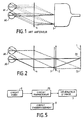
- Figure 1 shows a cathode ray tube, T, which emits rays in all directions and thus illuminates a collimating optic 4, which makes these rays roughly parallel to each other; the image of the tube provided by the optics is said to be collimated at infinity.
- the rays, at the exit of the optics 4 are not entirely parallel.
- the parallelism defect, or parallax defect can come from a bad focusing of the tube at the focus of the optics, residual aberrations could not be corrected during the optimization calculation of this optics (spherical aberration, coma, astigmatism, field curvature), machining or mounting faults (offsets, inclinations).
- the pupil receives rays coming from various points of the tube.
- the formation on the retina of rays corresponding to the same point of the tube does not create a point but a spot all the larger as the previous defects are important.
- the image seen is therefore more or less clear; this image can only be improved by adding lenses to the optics.
- the optical device which served to transmit the image comprises only one or two optical elements.
- the diameter of the exit pupil of an optical device cannot be reduced indefinitely because of the diffraction which will affect the quality of the image.
- the aberrations of the optics become negligible and the diffraction although visible on very small points is not it on the drawings which are used in the sights and which have a thickness of lines close or higher than the milliradian.
- the pupil of the eye has a diameter which naturally varies between 2 and 8 mm depending on the light environment.
- Figure 2 is a schematic view, in cross section, of an optical display device according to the invention, with an eye, shown in two different positions, AO and A1, in an area where it is expected that the display will take place .
- the device comprises, in series, a plane matrix of light-emitting diodes, which constitutes a light source 1, an optical condenser 2, an image generator 3 and a collimation optic 4.
- the light supplied by a source is considered to be coherent when the source emits in a cone with an angle less than or equal to the diffraction cone.
- each point of this generator must be lit by a very fine beam; very fine beams, to illuminate the image generator 3, are obtained by the formation on the pupil of the eye of the image of a diode of the matrix, that is to say that, depending from the position of the eye, it will be that of the diodes of the source 1, the image of which will form on the pupil of the eye, which will illuminate; thus, in position AO it is the diode DO which lights up while in position A1 it is the diode D1 which lights up.
- the aberration spot on the retina of the eye is very reduced, so that the image seen by the eye of the image provided by the generator and collimated at infinity, is clear even if the optics 4 is aberrant.
- a good depth of field is obtained and it is possible to move the collimation optics relative to the image generator 3 in order to modify the magnification of the image without, for this, disturbing the sharpness of the image seen.
- the light source 1 was a matrix of light-emitting diodes; the embodiments which will be described with the aid of FIGS. 3 and 4 also each include a source of this type, but other types of sources can be used.
- the source could, for example, be constituted by a simple light-emitting diode, by an incandescent filament lamp, by a laser ...; in these three cases the source will be moved or its light will be deflected according to the movements of the eye so that its image is constantly formed on the pupil of the eye.
- an optical reduction may be necessary to provide a sufficiently fine beam.
- It is also possible to combine the image generator and the point source by directly projecting the image onto the retina of the eye by scanning a directional beam, of the television scanning type, emitted for example by a laser.
- the production of a quasi-point light beam requires that there is no diffusing element between the light source and the eye.
- the image generator is constituted by a non-diffusing liquid crystal panel, placed between two polarizers; but other possibilities are available for producing the image generator, in particular that which was mentioned above and which groups together, using a laser, the light source and the generator; it is also possible to use, as image generator, a matrix valve, of the uniaxial and polar liquid crystal type, with its two polarizers placed on either side.
- FIG. 3 is a diagram which shows an optical device according to the invention, shown in more detail than that of FIG. 2.
- the oculometer 6 is worn by the helmet of the observer, that is to say that it is integral with the optical elements which go from the outlet of the fibers F to the mixing mirror M included; it determines the position of the eye by the coordinates of the center of the pupil of the eye with respect to these optical elements and sends this position information, in the form of an electrical signal, to a servo circuit 8.
- the circuit 8 includes a memory in which the addresses of the light-emitting diodes of the source 1 to be lit are stored, according to the eye position; a diode is lit when its image, that is to say the exit pupil of the device, is in the center of the pupil of the eye where it constitutes an illuminated zone.
- the illuminated zone of the pupil of the eye has a diameter of 0.6 mm and the movements of this zone are made in steps of 0.2 mm to follow movements of the eye by 2 , 6 mm on either side of a central point; these movements of the eye correspond to a visualization whose field is 30 degrees.
- the servo circuit 8 making correspond, at each point of the image produced by the image generator 3, a narrow beam which ends substantially at the center of the pupil of the eye A, the image seen by the eye is sharp.
- this image may be subject to distortions.
- these distortions are a function of the optical path taken by the rays of the beam, that is to say of the position of the diodes which are lit.
- the transcoder circuit 10 which receives from the servo circuit 8 the coordinates of the lit diodes and as a function of these coordinates corrects the theoretical coordinates of the image points provided by the video circuit; the transcoder circuit is therefore a circuit for controlling special effects of the type used in television.
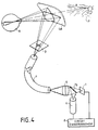
- Figure 4 is another embodiment showing an optical device according to the invention. This embodiment differs from that according to FIG. 3 in that the oculometer 6 is no longer worn by the helmet of the observer but is integral with the optical elements which go from the light source 1 included at the input of the fibers.
- F optics it is also distinguished in that, between the image generator 3 and the eye A of the observer, it is the visor of the helmet constituted by a concave semi-transparent mirror, 4m, through which the eye, A, observes the landscape, P, which plays both the role of collimation optics and of mixing mirror.
- the pupil of the eye is observed, by the oculometer 6, using a separating lens 7b constituted by a semi-transparent mirror placed on the optical path between projection optics 5 and the light source 1; as for the condenser 2 of FIG. 3, it is removed so as to lighten as much as possible the helmet of the observer on which are no longer mounted except the image generator and one end of the optical fibers F.
- This removal is possible because, in the example according to FIG. 4, the useful surface of the image generator 3 is much smaller (more than twice) than that of the collimating optic 4m.
- the resolution of the image seen by the eye is much lower than that obtained in the case of FIG. 3.
- the optical device according to FIG. 4 has been equipped, in one of its versions, with the electronic assembly according to FIG. 5 to correct the distortions brought about, in the image seen by the eye, by the collimation optics that constitutes the 4m mirror.
- the present invention is not limited to the examples described, thus it relates, in particular, to optical devices where the light source 1 would not transmit its light to the image generator 3 by a path including a conductor flexible optics but by a path of which all the elements are mechanically integral with one another; conversely he can be considered making an optical device according to the invention equipped with a flexible optical conductor disposed between the image generator and the eye.
- the invention also applies to the case where the image to be obtained must be in full color, the color being obtained, for example, by the fusion on the retina of the eye of three images generated, one in red, the another in green, the other in blue. Whatever the way of generating these three images and of carrying out the fusion on the retina of the eye, there is the possibility of compensating for the off-axis chromatic defects of the optical elements arranged on the path of each of the images; for this each image can be treated separately by a montage of the kind of that described with the help of FIG. 5.
- the invention also applies to devices intended for viewing infinitely collimated data without it being possible to simultaneously observe a landscape or any other view. It also applies to binocular visualization, the devices relating to the two eyes being able, thanks to semi-transparent mirrors, to have common parts but an oculometer and a separate servo circuit for each eye.
Landscapes
- Physics & Mathematics (AREA)
- Engineering & Computer Science (AREA)
- General Physics & Mathematics (AREA)
- Optics & Photonics (AREA)
- Theoretical Computer Science (AREA)
- Aviation & Aerospace Engineering (AREA)
- Educational Technology (AREA)
- Educational Administration (AREA)
- Business, Economics & Management (AREA)
- General Engineering & Computer Science (AREA)
- Holo Graphy (AREA)
- Eye Examination Apparatus (AREA)
- Liquid Crystal (AREA)
- Investigating Or Analysing Materials By The Use Of Chemical Reactions (AREA)
- Investigating, Analyzing Materials By Fluorescence Or Luminescence (AREA)
- Instruments For Viewing The Inside Of Hollow Bodies (AREA)
- Instrument Panels (AREA)
Applications Claiming Priority (2)
| Application Number | Priority Date | Filing Date | Title |
|---|---|---|---|
| FR8916397 | 1989-12-12 | ||
| FR8916397A FR2655742B1 (fr) | 1989-12-12 | 1989-12-12 | Dispositif optique pour la visualisation de donnees lumineuses collimatees a l'infini. |
Publications (2)
| Publication Number | Publication Date |
|---|---|
| EP0433145A1 EP0433145A1 (fr) | 1991-06-19 |
| EP0433145B1 true EP0433145B1 (fr) | 1994-05-25 |
Family
ID=9388405
Family Applications (1)
| Application Number | Title | Priority Date | Filing Date |
|---|---|---|---|
| EP90403490A Expired - Lifetime EP0433145B1 (fr) | 1989-12-12 | 1990-12-07 | Dispositif optique pour la visualisation de données lumineuses collimatées à l'infini |
Country Status (8)
| Country | Link |
|---|---|
| US (1) | US5170153A (da) |
| EP (1) | EP0433145B1 (da) |
| JP (1) | JPH04242715A (da) |
| AT (1) | ATE106148T1 (da) |
| CA (1) | CA2032076A1 (da) |
| DE (1) | DE69009158T2 (da) |
| DK (1) | DK0433145T3 (da) |
| FR (1) | FR2655742B1 (da) |
Cited By (1)
| Publication number | Priority date | Publication date | Assignee | Title |
|---|---|---|---|---|
| DE19906706A1 (de) * | 1999-02-18 | 2000-08-24 | Bayerische Motoren Werke Ag | Instrumentenfeld mit virtuellem Display |
Families Citing this family (34)
| Publication number | Priority date | Publication date | Assignee | Title |
|---|---|---|---|---|
| FR2683331B1 (fr) * | 1991-10-31 | 1994-09-23 | Thomson Csf | Jumelle a double image. |
| WO1995021440A1 (en) * | 1994-02-07 | 1995-08-10 | Virtual I/O, Inc. | Depixelated visual display |
| US6097543A (en) | 1992-02-07 | 2000-08-01 | I-O Display Systems Llc | Personal visual display |
| US5303085A (en) | 1992-02-07 | 1994-04-12 | Rallison Richard D | Optically corrected helmet mounted display |
| US5864326A (en) | 1992-02-07 | 1999-01-26 | I-O Display Systems Llc | Depixelated visual display |
| US5526022A (en) | 1993-01-06 | 1996-06-11 | Virtual I/O, Inc. | Sourceless orientation sensor |
| US5410371A (en) * | 1993-06-07 | 1995-04-25 | The United States Of America As Represented By The Administrator Of The National Aeronautics And Space Administration | Display system employing acoustro-optic tunable filter |
| JPH0772446A (ja) * | 1993-09-01 | 1995-03-17 | Sharp Corp | 表示システム |
| FR2709854B1 (fr) * | 1993-09-07 | 1995-10-06 | Sextant Avionique | Dispositif de visualisation à couleurs optimisées. |
| US5991087A (en) | 1993-11-12 | 1999-11-23 | I-O Display System Llc | Non-orthogonal plate in a virtual reality or heads up display |
| DE4339606A1 (de) * | 1993-11-20 | 1995-05-24 | Bodenseewerk Geraetetech | Piloten-Trainingsgerät |
| US6160666A (en) | 1994-02-07 | 2000-12-12 | I-O Display Systems Llc | Personal visual display system |
| US5619370A (en) * | 1994-03-28 | 1997-04-08 | Guinosso; Patrick J. | Optical system for viewing a remote location |
| US5903395A (en) | 1994-08-31 | 1999-05-11 | I-O Display Systems Llc | Personal visual display system |
| US5583795A (en) * | 1995-03-17 | 1996-12-10 | The United States Of America As Represented By The Secretary Of The Army | Apparatus for measuring eye gaze and fixation duration, and method therefor |
| US5991085A (en) | 1995-04-21 | 1999-11-23 | I-O Display Systems Llc | Head-mounted personal visual display apparatus with image generator and holder |
| JP2973867B2 (ja) * | 1995-05-26 | 1999-11-08 | 日本電気株式会社 | 視点追従型立体表示装置および視点追従方法 |
| US5657163A (en) * | 1995-05-31 | 1997-08-12 | Delco Electronics Corporation | Fiber optic illumination of HUD image source |
| DE19540108C2 (de) * | 1995-10-27 | 1998-08-06 | Ldt Gmbh & Co | Vorrichtung zur Darstellung eines ersten Bildes in einem durch eine durchsichtige Scheibe sichtbaren zweiten Bild |
| US6750832B1 (en) | 1996-12-20 | 2004-06-15 | Siemens Aktiengesellschaft | Information display system for at least one person |
| FR2762688B1 (fr) * | 1997-04-29 | 1999-07-16 | Sextant Avionique | Systeme optique combinant une presentation d'image et une analyse de l'oeil |
| US5903396A (en) | 1997-10-17 | 1999-05-11 | I/O Display Systems, Llc | Intensified visual display |
| FR2809950B1 (fr) * | 2000-06-09 | 2004-07-09 | Plexus | Dispositif de transport d'image en lumiere coherente |
| WO2002086591A1 (en) * | 2001-04-23 | 2002-10-31 | Reveo, Inc. | Image display system and electrically actuatable image combiner therefor |
| EP1395868A1 (de) * | 2001-05-22 | 2004-03-10 | Physoptics Opto-Electronic GmbH | Verfahren und system zum zurverfuegungstellen von informationen über das auge. |
| US8035576B2 (en) * | 2007-02-20 | 2011-10-11 | Canon Kabushiki Kaisha | Head-mounted display and head-mounted video display |
| US9076368B2 (en) | 2012-02-06 | 2015-07-07 | Battelle Memorial Institute | Image generation systems and image generation methods |
| US8982014B2 (en) | 2012-02-06 | 2015-03-17 | Battelle Memorial Institute | Image generation systems and image generation methods |
| US10317677B2 (en) | 2015-02-09 | 2019-06-11 | Microsoft Technology Licensing, Llc | Display system |
| US11086216B2 (en) | 2015-02-09 | 2021-08-10 | Microsoft Technology Licensing, Llc | Generating electronic components |
| US10018844B2 (en) * | 2015-02-09 | 2018-07-10 | Microsoft Technology Licensing, Llc | Wearable image display system |
| CN110447224B (zh) | 2017-03-07 | 2022-03-22 | 8259402加拿大有限公司 | 在显示器中控制虚像的方法 |
| JP7626586B2 (ja) * | 2019-09-03 | 2025-02-07 | 株式会社島津製作所 | 画像表示装置 |
| CN115671574B (zh) * | 2021-07-21 | 2025-10-24 | 苏州宣嘉光电科技有限公司 | 一种视力精准化治疗仪及其使用的治疗光功率调整方法 |
Family Cites Families (12)
| Publication number | Priority date | Publication date | Assignee | Title |
|---|---|---|---|---|
| US3915548A (en) * | 1973-04-30 | 1975-10-28 | Hughes Aircraft Co | Holographic lens and liquid crystal image source for head-up display |
| US4109145A (en) * | 1974-05-20 | 1978-08-22 | Honeywell Inc. | Apparatus being controlled by movement of the eye |
| US4028725A (en) * | 1976-04-21 | 1977-06-07 | Grumman Aerospace Corporation | High-resolution vision system |
| GB1578136A (en) * | 1977-06-20 | 1980-11-05 | Hawker Siddeley Aviation Ltd | Helmet-mounted sights |
| GB2009071B (en) * | 1977-11-25 | 1982-01-20 | Elliott Brothers London Ltd | Head-up display systems |
| GB2115946B (en) * | 1978-12-21 | 1984-02-01 | Redifon Simulation Ltd | Improvements in or relating to visual display apparatus |
| GB2043289A (en) * | 1979-01-11 | 1980-10-01 | Redifon Simulation Ltd | Improvements in or relating to visual display apparatus |
| US4439755A (en) * | 1981-06-04 | 1984-03-27 | Farrand Optical Co., Inc. | Head-up infinity display and pilot's sight |
| FR2607598B1 (fr) * | 1986-11-28 | 1989-02-24 | Sfena | Dispositif de visualisation a structure dissociable, notamment pour aeronef |
| US4880287A (en) * | 1987-01-06 | 1989-11-14 | Hughes Aircraft Company | Complex conjugate hologram display |
| US4897715A (en) * | 1988-10-31 | 1990-01-30 | General Electric Company | Helmet display |
| US4950069A (en) * | 1988-11-04 | 1990-08-21 | University Of Virginia | Eye movement detector with improved calibration and speed |
-
1989
- 1989-12-12 FR FR8916397A patent/FR2655742B1/fr not_active Expired - Fee Related
-
1990
- 1990-12-04 US US07/621,879 patent/US5170153A/en not_active Expired - Fee Related
- 1990-12-07 DK DK90403490.7T patent/DK0433145T3/da active
- 1990-12-07 AT AT90403490T patent/ATE106148T1/de not_active IP Right Cessation
- 1990-12-07 DE DE69009158T patent/DE69009158T2/de not_active Expired - Fee Related
- 1990-12-07 EP EP90403490A patent/EP0433145B1/fr not_active Expired - Lifetime
- 1990-12-11 JP JP2415725A patent/JPH04242715A/ja active Pending
- 1990-12-12 CA CA002032076A patent/CA2032076A1/en not_active Abandoned
Cited By (1)
| Publication number | Priority date | Publication date | Assignee | Title |
|---|---|---|---|---|
| DE19906706A1 (de) * | 1999-02-18 | 2000-08-24 | Bayerische Motoren Werke Ag | Instrumentenfeld mit virtuellem Display |
Also Published As
| Publication number | Publication date |
|---|---|
| DE69009158D1 (de) | 1994-06-30 |
| FR2655742A1 (fr) | 1991-06-14 |
| FR2655742B1 (fr) | 1992-01-17 |
| DE69009158T2 (de) | 1994-09-08 |
| ATE106148T1 (de) | 1994-06-15 |
| DK0433145T3 (da) | 1994-06-20 |
| JPH04242715A (ja) | 1992-08-31 |
| EP0433145A1 (fr) | 1991-06-19 |
| US5170153A (en) | 1992-12-08 |
| CA2032076A1 (en) | 1991-06-13 |
Similar Documents
| Publication | Publication Date | Title |
|---|---|---|
| EP0433145B1 (fr) | Dispositif optique pour la visualisation de données lumineuses collimatées à l'infini | |
| EP0365406B1 (fr) | Système optique de collimation notamment pour visuel de casque | |
| EP0194196B1 (fr) | Système aéroporté de visualisation d'images collimatées | |
| FR2638242A1 (fr) | Systeme optique de collimation, notamment pour visuel de casque | |
| US20040174599A1 (en) | Device and method for the laser projection of high-resolution images onto the retina of the eye, superimposed with the image content of the field of vision | |
| EP0487385B1 (fr) | Dispositif de visualisation collimaté à miroir sphérique hors d'axe pour simulateur | |
| FR2784201A1 (fr) | Dispositif optique pour viseur de casque comportant un miroir diffractif | |
| EP0443025A1 (en) | Helmet mounted display | |
| WO1999019757A1 (fr) | Dispositif optique pour viseur de casque comportant un miroir de mangin | |
| FR2996650A1 (fr) | Affichage tete haute pour vehicule automobile | |
| FR3034531A1 (fr) | Affichage tete haute auto-stereoscopie du vehicule et procede pour generer une telle image | |
| US9470891B2 (en) | Head-up display for night vision goggles | |
| EP1000375B1 (fr) | Dispositif optique pour viseur de casque comportant un miroir aspherique | |
| EP1223455B1 (fr) | Viseur tête haute apte à s'adapter à des équipements d'un type donné | |
| EP1258771A1 (fr) | Architecture optique à encombrement réduit pour viseur de casque grand champ | |
| EP0990188B1 (fr) | Dispositif de visualisation pour visuel de casque | |
| EP1057069B1 (fr) | Dispositif optique pour viseur de casque comportant un miroir tubulaire | |
| FR3115894A1 (fr) | Appareil de projection d’images et unité de pilotage associée | |
| FR2903786A1 (fr) | Systeme de visualisation de casque a modules optiques interchangeables | |
| CA2110075A1 (fr) | Systeme de visualisation monte sur casque | |
| CA2084908C (fr) | Dispositif pour determiner la portion d'un champ regardee par l'oeil d'un observateur | |
| EP0635743A1 (fr) | Dispositif optique binoculaire à résolution et/ou champ de vision augmenté, notamment pour la vision nocturne | |
| EP4264351B1 (fr) | Jumelles de vision nocturne | |
| WO2025083201A1 (fr) | Système optique de vision | |
| EP4411449A1 (en) | Thin beam generation device |
Legal Events
| Date | Code | Title | Description |
|---|---|---|---|
| PUAI | Public reference made under article 153(3) epc to a published international application that has entered the european phase |
Free format text: ORIGINAL CODE: 0009012 |
|
| AK | Designated contracting states |
Kind code of ref document: A1 Designated state(s): AT BE CH DE DK FR GB LI NL SE |
|
| 17P | Request for examination filed |
Effective date: 19911123 |
|
| 17Q | First examination report despatched |
Effective date: 19931004 |
|
| GRAA | (expected) grant |
Free format text: ORIGINAL CODE: 0009210 |
|
| AK | Designated contracting states |
Kind code of ref document: B1 Designated state(s): AT BE CH DE DK FR GB LI NL SE |
|
| REF | Corresponds to: |
Ref document number: 106148 Country of ref document: AT Date of ref document: 19940615 Kind code of ref document: T |
|
| REG | Reference to a national code |
Ref country code: DK Ref legal event code: T3 |
|
| REF | Corresponds to: |
Ref document number: 69009158 Country of ref document: DE Date of ref document: 19940630 |
|
| GBT | Gb: translation of ep patent filed (gb section 77(6)(a)/1977) |
Effective date: 19940623 |
|
| EAL | Se: european patent in force in sweden |
Ref document number: 90403490.7 |
|
| PLBE | No opposition filed within time limit |
Free format text: ORIGINAL CODE: 0009261 |
|
| STAA | Information on the status of an ep patent application or granted ep patent |
Free format text: STATUS: NO OPPOSITION FILED WITHIN TIME LIMIT |
|
| 26N | No opposition filed | ||
| REG | Reference to a national code |
Ref country code: FR Ref legal event code: CL |
|
| PGFP | Annual fee paid to national office [announced via postgrant information from national office to epo] |
Ref country code: NL Payment date: 19981116 Year of fee payment: 9 |
|
| PGFP | Annual fee paid to national office [announced via postgrant information from national office to epo] |
Ref country code: SE Payment date: 19981126 Year of fee payment: 9 |
|
| PGFP | Annual fee paid to national office [announced via postgrant information from national office to epo] |
Ref country code: BE Payment date: 19981204 Year of fee payment: 9 |
|
| PGFP | Annual fee paid to national office [announced via postgrant information from national office to epo] |
Ref country code: DK Payment date: 19981214 Year of fee payment: 9 |
|
| PGFP | Annual fee paid to national office [announced via postgrant information from national office to epo] |
Ref country code: CH Payment date: 19981229 Year of fee payment: 9 |
|
| PGFP | Annual fee paid to national office [announced via postgrant information from national office to epo] |
Ref country code: AT Payment date: 19981230 Year of fee payment: 9 |
|
| PG25 | Lapsed in a contracting state [announced via postgrant information from national office to epo] |
Ref country code: DK Free format text: LAPSE BECAUSE OF NON-PAYMENT OF DUE FEES Effective date: 19991207 Ref country code: AT Free format text: LAPSE BECAUSE OF NON-PAYMENT OF DUE FEES Effective date: 19991207 |
|
| PG25 | Lapsed in a contracting state [announced via postgrant information from national office to epo] |
Ref country code: SE Free format text: LAPSE BECAUSE OF NON-PAYMENT OF DUE FEES Effective date: 19991208 |
|
| PG25 | Lapsed in a contracting state [announced via postgrant information from national office to epo] |
Ref country code: LI Free format text: LAPSE BECAUSE OF NON-PAYMENT OF DUE FEES Effective date: 19991231 Ref country code: CH Free format text: LAPSE BECAUSE OF NON-PAYMENT OF DUE FEES Effective date: 19991231 Ref country code: BE Free format text: LAPSE BECAUSE OF NON-PAYMENT OF DUE FEES Effective date: 19991231 |
|
| BERE | Be: lapsed |
Owner name: SEXTANT AVIONIQUE Effective date: 19991231 |
|
| PG25 | Lapsed in a contracting state [announced via postgrant information from national office to epo] |
Ref country code: NL Free format text: LAPSE BECAUSE OF NON-PAYMENT OF DUE FEES Effective date: 20000701 |
|
| EUG | Se: european patent has lapsed |
Ref document number: 90403490.7 |
|
| NLV4 | Nl: lapsed or anulled due to non-payment of the annual fee |
Effective date: 20000701 |
|
| REG | Reference to a national code |
Ref country code: DK Ref legal event code: EBP |
|
| PGFP | Annual fee paid to national office [announced via postgrant information from national office to epo] |
Ref country code: DE Payment date: 20001122 Year of fee payment: 11 |
|
| PGFP | Annual fee paid to national office [announced via postgrant information from national office to epo] |
Ref country code: GB Payment date: 20001124 Year of fee payment: 11 |
|
| PGFP | Annual fee paid to national office [announced via postgrant information from national office to epo] |
Ref country code: FR Payment date: 20001221 Year of fee payment: 11 |
|
| PG25 | Lapsed in a contracting state [announced via postgrant information from national office to epo] |
Ref country code: GB Free format text: LAPSE BECAUSE OF NON-PAYMENT OF DUE FEES Effective date: 20011207 |
|
| REG | Reference to a national code |
Ref country code: GB Ref legal event code: IF02 |
|
| PG25 | Lapsed in a contracting state [announced via postgrant information from national office to epo] |
Ref country code: DE Free format text: LAPSE BECAUSE OF NON-PAYMENT OF DUE FEES Effective date: 20020702 |
|
| GBPC | Gb: european patent ceased through non-payment of renewal fee |
Effective date: 20011207 |
|
| PG25 | Lapsed in a contracting state [announced via postgrant information from national office to epo] |
Ref country code: FR Free format text: LAPSE BECAUSE OF NON-PAYMENT OF DUE FEES Effective date: 20020830 |
|
| REG | Reference to a national code |
Ref country code: FR Ref legal event code: ST |