EP0433114B1 - Method and apparatus for measuring the edge thickness of a spectacle lens - Google Patents
Method and apparatus for measuring the edge thickness of a spectacle lens Download PDFInfo
- Publication number
- EP0433114B1 EP0433114B1 EP19900403223 EP90403223A EP0433114B1 EP 0433114 B1 EP0433114 B1 EP 0433114B1 EP 19900403223 EP19900403223 EP 19900403223 EP 90403223 A EP90403223 A EP 90403223A EP 0433114 B1 EP0433114 B1 EP 0433114B1
- Authority
- EP
- European Patent Office
- Prior art keywords
- radius vector
- measuring
- edge thickness
- lens
- information
- Prior art date
- Legal status (The legal status is an assumption and is not a legal conclusion. Google has not performed a legal analysis and makes no representation as to the accuracy of the status listed.)
- Expired - Lifetime
Links
- 238000000034 method Methods 0.000 title claims description 16
- 238000005259 measurement Methods 0.000 claims description 7
- 238000009432 framing Methods 0.000 claims description 4
- 102000006479 Heterogeneous-Nuclear Ribonucleoproteins Human genes 0.000 claims 1
- 108010019372 Heterogeneous-Nuclear Ribonucleoproteins Proteins 0.000 claims 1
- 238000010586 diagram Methods 0.000 description 6
- 239000000463 material Substances 0.000 description 4
- 239000003795 chemical substances by application Substances 0.000 description 1
- 238000007796 conventional method Methods 0.000 description 1
- 238000001514 detection method Methods 0.000 description 1
- 238000006073 displacement reaction Methods 0.000 description 1
- 239000011521 glass Substances 0.000 description 1
- 230000010365 information processing Effects 0.000 description 1
- 238000012986 modification Methods 0.000 description 1
- 230000004048 modification Effects 0.000 description 1
- 239000004570 mortar (masonry) Substances 0.000 description 1
- 230000003287 optical effect Effects 0.000 description 1
- 230000002093 peripheral effect Effects 0.000 description 1
Images


Classifications
-
- B—PERFORMING OPERATIONS; TRANSPORTING
- B24—GRINDING; POLISHING
- B24B—MACHINES, DEVICES, OR PROCESSES FOR GRINDING OR POLISHING; DRESSING OR CONDITIONING OF ABRADING SURFACES; FEEDING OF GRINDING, POLISHING, OR LAPPING AGENTS
- B24B47/00—Drives or gearings; Equipment therefor
- B24B47/22—Equipment for exact control of the position of the grinding tool or work at the start of the grinding operation
- B24B47/225—Equipment for exact control of the position of the grinding tool or work at the start of the grinding operation for bevelling optical work, e.g. lenses
Definitions
- This invention relates to methods for measuring the edge thickness of a spectacle lens.
- This conventional apparatus for measuring the edge thickness is constituted such that the thickness can be measured based on the lens rim shape of the spectacle frame measured by the frame shape measuring device 10 as shown schematically in Fig. 6.
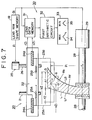
- the edge thickness measuring apparatus is shown as a block diagram in Fig. 7.
- the frame shape measuring apparatus 10 has a symmetric rotator with hexagon-sectional shapes shaped feeler 11 mounted rotatably in the tip.
- the feeler 11 is connected with a feeler arm 12, which is rotatable about the axis of the perpendicular line As through the edge of contact 11a of the feeler 11, supported by a feeler supporting base 13.
- the base 13 is mounted on the rail 14 turned round by a pulse motor 16 and movable by elasticity of a spring 15 fixed to another edge (not shown) of the rail 14.
- the pulse motor 16 can work by the pulse from a pulse generator 17.
- the moving amount ⁇ i of the feeler 11 is detected by a detector 19 constituted of either an encoder or a position sensor.
- the detected moving amount ⁇ i is memorized in a lens rim shape memory 18 together with a supply pulse ⁇ i to the pulse motor 16.
- the moving amount ⁇ i of the feeler is measured over the V-edge groove all around of the lens rim F.
- the edge thickness measuring apparatus comprises an edge thickness sensor portion 20 and an electric circuit portion 30.
- the sensor portion 20 includes a lens feeler supporting member 22, which is moved on the guide rail 21 by the driving of a feed screw 26. The screw 26 is rotated by the pulse motor 25. A material lens L is held between lens rotating shafts 28,28 and then the lens L is rotated by the rotation of the shafts 28,28 caused by the driving of the pulse motor 29.
- the lens feeler supporting member 22 includes lens feelers 23A,23B and detectors 24A,24B.
- the detectors 24A,24B are constituted of springs 25A,25B for pulling the lens feelers 23A,24B, and encoders or position sensors for detecting the moving amount of the feelers 23A,23B.
- the pulse based on the length ⁇ i of the radius vector of the radius vector information ( ⁇ i , ⁇ i ) of the lens rim F is supplied into the pulse motor 25, and the feelers 23A,23B moves inside the lens feeler supporting member 22. This movement determines the position of the lens feelers 23A,23B at the point having the length ⁇ i of the radius vector from the axis of rotation of the lens rotating shafts.
- the length ⁇ i of the radius vector is memorized in the lens rim shape memory 18.
- the pulse based on the rotary angle (radius vector angle) ⁇ i is supplied to the pulse motor 29 and then the lens rotating shafts 28,28 are rotated.
- This rotation of the shafts 28,28 produces the rotation of the material lens L by the rotary angle ⁇ i from the reference position.
- the lens feeler 23A is moved by the elasticity of the spring 25A and then abutted on the front side refraction surface IF of the material lens L.
- the moving amount f Z i is detected by the detector 24A and memorized in a lens data memory 31.
- the lens feeler 23B is moved by the elasticity of the spring 25B and then abutted on the back side refraction surface LB and the moving amount b Z i is detected by the detector 24B and memorized in a lens data memory 31.
- the lens L is automatically ground. And formed is a configuration that the sectional shape of the lens L is graphically displayed on a display 33.
- the positions of the contact of the lens feelers 23A,23B with the lens L is taken on the tangent line Q through the V-edge apex Y formed in the V-edge grinding of the lens.
- the edge thickness ⁇ i on the tangent line Q is calculated by the first arithmetic circuit 32.
- the radius of curvature R of the front surface of the lens L is different from that of the back(rear)surface, and the edge thickness of the base B of the edge surface of the lens L to form a V-edge is exactly ⁇ i ′. Therefore the calculation of the treated V-edge apex position information ( k Z i , ⁇ i , ⁇ i ) not based on the edge thickness ⁇ i ′ of the base B is inaccurate.
- V-edge apex position information ( k Z i , ⁇ i , ⁇ i ) is calculated based on the edge thickness ⁇ i ' when the lens is ground with the grinder G. As shown in Fig.
- V-edge (V-ridge) formed actually on the lens L is an inadequate V-edge in case the edge thickness is smaller than the width (W) of V-edge groove of the grinder G, because the edge surface K of the lens L to grind actually is displaced from the position of the measured edge surface KM owing to the difference between the radius of curvature R f of the front surface of the lens L and the radius of curvature R b of the back surface, in case even if the V-edge apex position information ( k Z i , ⁇ i , ⁇ i ) is obtained based on the edge thickness ⁇ i ' measured by the above method such that the V-edge apex Y is formed at the point where the edge thickness is divided in the ratio of one to one, for example.
- feelers On a lens measuring device are provided feelers contacting respectively the front and rear surfaces of a workpiece lens and magnetic encoders for detecting the displacements of the feelers.
- movable stages move the feelers along a measure locus on the lens in a predetermined relationship with a supposed edge locus obtained from the shape data of a lens frame of an eye glass frame into which is inserted the lens or the shape data of the lens profiled according to a template.
- a calculating means provided in the measuring device figures out the edge thickness of lens after mortar working on the basis of the detecting information of the encoders when the feelers are moved on the measured locus.
- Fig. 1 is a block diagram showing a constitution of the embodiment of the edge thickness measuring apparatus according to the present invention.
- a first arithmetic circuit 32 in Fig. 1 calculates an edge thickness information ( ⁇ i , ⁇ i ) from a front and back surface position informations ( f Z i , ⁇ i ), ( b Z i , ⁇ i ) of a material lens L as a lens to grind which is detected by detectors 24A,24B.
- This first arithmetic circuit 32 also connects with a comparison circuit 41.
- the comparison circuit 41 connects with a grinder shape memory 42 which keeps memorizing an already-known V-edge base width W and a V-edge height H.
- the second arithmetic circuit 43 connects with a lens rim shape memory 18 of a frame shape measuring apparatus 10, the comparison circuit 41, and the grinder shape memory 42.
- radius vector information all round radius vector information
- the memory 18 and the second arithmetic circuit 43 act as an input means and an arithmetic means, respectively.
- the length ( ⁇ i ′) obtained is input in a pulse motor 29.
- the pulse motors 25,29 are driven and controlled by the second arithmetic circuit 43, corresponding to the measuring radius vector information ( ⁇ i ′, ⁇ i ).
- the driving of the pulse motors 25,29 makes the lens feelers 23A,23B move to position them (23A,23B) at the measuring point ⁇ i (as shown in Figs. 3A,3B).
- the moving amount of the lens feelers 23A,23B is detected in terms of the front and back surface position informations ( f Z i , ⁇ i ), ( b Z i , ⁇ i ) of the lens L by the detectors 24A,24B. And then, as shown in Figs.
- the measurement of the edge thickness is carried out over the all round of the radius vector locus S to be measured, that is, all of the measuring points from the 0-th measuring point to the N-th measuring point.
- the first arithmetic circuit 32 acts as an edge thickness measuring means.
- the grinder shape memory 42 acts as a memorizing means and the comparison circuit 41 acts as a comparing means.
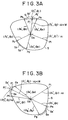
- Fig. 3A shows the lens L as a minus lens.
- Fig. 3B shows the lens L as a plus lens.
- these measuring radius vector lengths ⁇ j ′ and edge thicknesses ⁇ j are input into the second arithmetic circuit 43.
- H:W (H-d j ): ⁇ j
- H is a V-edge height and W is a V-edge base width of a V-edge grinder G and d j is a compensated amount.
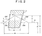
- the pulse motors 25,29 driven and controlled based on these inputs move the lens feelers 23A and 23B to the positions 23A′, 23B′ as shown in Fig. 2.
- the lens feelers 23A and 23B measure the front and back surface position informations ( f Z j ′, ⁇ j ), ( b Z j ′, ⁇ j ) of the lens L on the partial re-measuring loci S1′ through S4′ as shown in Figs. 3A and 3B.
- FIGs. 4 and 5 are schematic illustration showing another edge thickness measuring method with the above mentioned edge thickness measuring apparatus.
- the second arithmetic circuit 43 inputs the 0-th measuring radius vector ( ⁇ 0′) in the pulse motor 25 and the 0-th radius vector angle ( ⁇ 0).
- the driving of the pulse motors 25,29 makes the lens feelers 23A,23B move to the measuring point P0 (see Figs. 3A and 3B).
- the lens feelers 23A,23B at the point P abut on the lens L by elasticity of the springs 25A,25B.
- the moving amount of the lens feelers 23A,23B are detected as the 0-th front surface position information ( f Z0, ⁇ 0) and the 0-th back surface position information ( b Z0, ⁇ 0) of the lens L by the detectors 24A,24B.
- the 0-th edge thickness ⁇ 0 is broader than the V-edge base width W in the example of Fig. 4. Therefore, the second arithmetic circuit 43 inputs the length ⁇ 1′ of the 1st measuring radius, vectorwhich follows the 0-th thickness into the pulse motor 25 and the first radius vector angle ⁇ 1, into the pulse motor 29. And the lens feelers 23A,23B are moved to and placed at the first measuring position P1.
- the moving amounts of the lens feelers 23A,23B are detected in terms of the first front surface position information ( f Z1, ⁇ 1) and the first back surface position information ( b Z1, ⁇ 1) of the lens L by the detectors 24A,24B. And the first arithmetic circuit 32 calculates the ⁇ 1 of the first edge thickness information ( ⁇ 1, ⁇ 1) at the first measuring point P1 from the information ( f Z1, ⁇ 1), ( b Z1, ⁇ 1) the same as (2′).
- the first edge thickness information ( ⁇ 1, ⁇ 1) calculated by the first arithmetic circuit 32 is compared with the V-edge base width W of the V-edge grinder G memorized in the grinder shape memory 42 by the comparison circuit 41.
- the first edge thickness ⁇ 1 is broader than the V-edge base width W in the example of Fig. 4.
- the same procedures are in order followed to the j-th measuring radius vector information ( ⁇ j ′, ⁇ j ) judged that the edge thickness ⁇ j is narrower than the V-edge base width W.
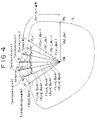
- the second arithmetic circuit 43 changes the length ⁇ j+1 ′ of the (j+1)th measuring radius vector of the (j+1)th measuring radius vector information ( ⁇ j+1 , ⁇ j+1 ) into the first compensated radius vector length ⁇ j+1 as shown in Fig. 4.
- the second arithmetic circuit 43 inputs the first compensated radius vector length ⁇ j+i into the pulse motor 25 and the first compensated radius vector angle ⁇ j+i (equivalent to the (j+i)th measuring radius vector angle ⁇ j+i ) into the pulse motor 29. And the lens feelers 23A and 23B are moved to the position of the first compensated measuring point T j+1 in Figs. 4 and 5(b) based on these inputs.
- the first arithmetic circuit 32 obtains the j+1 edge thickness ⁇ j+1 from the front and back surface position informations of the lens L at the first compensated measuring point T j+1 .
- the comparison circuit 41 compares the (j+1)th edge thickness ⁇ j+1 with the j-th edge thickness ⁇ j preceding to ⁇ j+1 .
- the second arithmetic circuit 43 changes the following (j+2)th measuring radius vector length ⁇ j+2 ′ of the (j+2)th measuring radius vector information ( ⁇ j+2 ′, ⁇ j+2 ) into the second compensated radius vector length ⁇ j+2 as shown in Fig. 4.
- the second arithmetic circuit 43 inputs the second compensated radius vector length ⁇ j+2 into the pulse motor 25 and the second compensated radius vector angle ⁇ j+2 (equivalent to the (j+2)th measuring radius vector angle ⁇ j+2 ) into the pulse motor29, respectively.
- the lens feelers 23A,23B move to the second compensated measuring point T j+2 shown in Fig. 4 and Fig. 5(c) based on these inputs.
- the first arithmetic circuit 32 After the measurement of the front and back surface position informations of the lens L at the second compensated measuring point T j+2 , the first arithmetic circuit 32 obtains the (j+2)th edge thickness ⁇ j+2 .
- the comparison circuit 41 compares the (j+2)th edge thickness ⁇ j+2 with the (j+1)th edge thickness preceding to the (j+2)th thickness.
- the second arithmetic circuit 43 changes the following (j+3)th measuring radius vector length ⁇ j+3 ′ of the (j+3)th measuring radius vector information ( ⁇ j+3 ′, ⁇ j+3 ) into the third compensated radius vector length ⁇ j+3 .
- the second arithmetic circuit 43 inputs the third compensated radius vector length ⁇ j+3 into the pulse motor 25 and the third compensated radius vector angle ⁇ j+3 (equivalent to the (j+3)th measuring radius vector angle ⁇ j+3 ) into the pulse motor29, respectively.
- the lens feelers 23A,23B are moved to the third compensated measuring point T j+3 as shown in Figs. 4 and 5(d). And then the lens feelers 23A,23B are moved to the third compensated measuring point T j+3 as shown in Figs. 4 and 5(d).
- the front and back surface position information s of the lens L as the third compensated measuring point T j+3 are measured, and then the first arithmetic circuit 32 calculates the (j+3)th edge thickness ⁇ j+3 . And the comparison circuit 41 compares the (j+3)th edge thickness ⁇ j+3 with the preceding (j+2)th edge thickness ⁇ j+2 .
- the second arithmetic circuit 43 changes the following (j+4)th measuring radius vector length ⁇ j+4 ′ of the (j+4) measuring radius vector information ( ⁇ j+4 ', ⁇ j+4 ) into the fourth compensated radius vector length ⁇ j+4 as shown in Fig. 4.
- the second arithmetic circuit 43 inputs the fourth compensated radius vector length ⁇ j+4 into the pulse motor 25 and the fourth compensated radius vector angle ⁇ j+4 (equivalent to the (j+4)th measuring radius vector angle ⁇ j+4 ) into the pulse motor29, respectively. And then the lens feelers 23A,23B are moved to the fourth compensated measuring point T j+4 as shown in Figs. 4 and 5(e).
- the front and back surface position information s of the lens L as the fourth compensated measuring point T j+4 are measured,and then the first arithmetic circuit 32 calculates the (j+4)th edge thickness ⁇ j+4 .
- comparison circuit 41 compares the (j+4)th edge thickness ⁇ j+4 with the preceding (j+3)th edge thickness ⁇ j+3 .
- the following (j+5)th measuring radius vector information ( ⁇ j+5 ′, ⁇ j+5 ) does not need to be changed,and the measuring of the edge thickness at the measuring point T j+5 on the measuring radius vector locus S as shown in Fig. 5(f) is carried out.
- the measuring edge thickness ⁇ j first turns narrower than the V-edge base width W
- the following first compensated measuring radius vector length ⁇ j+1 for the (j+1)th measuring radius vector ⁇ j+1 ′ is changed from the first compensated amount t1 of the formula (6) to the formula (7):
- ⁇ j+1 ⁇ j+1 ′+t1
- the (j+1)th edge thickness is measured at the (j+1)th measuring point T j+1 as a changed position.
- the second compensated measuring radius vector length ⁇ j+2 and the measuring edge thickness ⁇ j+m-1 preceding to the ⁇ j+2 is changed into the (m)th compensated measuring radius vector length ⁇ j+m broader than the V-edge base width W.
- the (m)th compensated amount tm in a generalized formula of the formulas (8) through (13) is expressed as follows :
- the (m)th compensated measuring radius vector length ⁇ j+m is:
- the measurement of the thickness is carried out at the compensated measuring point on the compensated locus S′ shown with the stitch line in Fig. 4.
- the present invention can provide a method and an apparatus for measuring the edge thickness of a spectacle lens, which has an advantage to measure more accurately the edge thickness of the lens narrower than the width of the V-edge base of the V-edge grinder in comparison with the prior art.
Landscapes
- Engineering & Computer Science (AREA)
- Mechanical Engineering (AREA)
- Grinding And Polishing Of Tertiary Curved Surfaces And Surfaces With Complex Shapes (AREA)
- Length Measuring Devices With Unspecified Measuring Means (AREA)
Description
- This invention relates to methods for measuring the edge thickness of a spectacle lens.
- An example of a conventional method and apparatus for measuring the edge thickness of a lens is in detail described in Japanese Patent Application No. SHO 60-115079 as a component of a lens grinding apparatus disclosed by the same applicant as in the present application.
- This conventional apparatus for measuring the edge thickness is constituted such that the thickness can be measured based on the lens rim shape of the spectacle frame measured by the frame
shape measuring device 10 as shown schematically in Fig. 6. The edge thickness measuring apparatus is shown as a block diagram in Fig. 7. - The frame
shape measuring apparatus 10 has a symmetric rotator with hexagon-sectional shapes shaped feeler 11 mounted rotatably in the tip. The feeler 11 is connected with afeeler arm 12, which is rotatable about the axis of the perpendicular line As through the edge of contact 11a of the feeler 11, supported by afeeler supporting base 13. And thebase 13 is mounted on therail 14 turned round by apulse motor 16 and movable by elasticity of aspring 15 fixed to another edge (not shown) of therail 14. Thepulse motor 16 can work by the pulse from apulse generator 17. - When the edge of contact 11a of the feeler 11 is abutted on the V-edge groove Vf, the moving amount ρi of the feeler 11 is detected by a
detector 19 constituted of either an encoder or a position sensor. The detected moving amount ρi is memorized in a lensrim shape memory 18 together with a supply pulse ϑi to thepulse motor 16. - The moving amount ρi of the feeler and the rotational amount of the arm, i.e. the radius vector angle ϑi are memorized as a radius vector information (ρi, ϑi) (i=0,1,2,3...N) of the lens rim F in the lens
rim shape memory 18. The moving amount ρi of the feeler is measured over the V-edge groove all around of the lens rim F. - As shown in Fig. 7, the edge thickness measuring apparatus comprises an edge
thickness sensor portion 20 and anelectric circuit portion 30. Thesensor portion 20 includes a lensfeeler supporting member 22, which is moved on theguide rail 21 by the driving of afeed screw 26. Thescrew 26 is rotated by thepulse motor 25. A material lens L is held betweenlens rotating shafts shafts pulse motor 29. The lensfeeler supporting member 22 includeslens feelers detectors detectors springs lens feelers feelers - The pulse based on the length ρi of the radius vector of the radius vector information (ρi, ϑi) of the lens rim F is supplied into the
pulse motor 25, and thefeelers feeler supporting member 22. This movement determines the position of thelens feelers rim shape memory 18. On the other hand, the pulse based on the rotary angle (radius vector angle) ϑi is supplied to thepulse motor 29 and then thelens rotating shafts shafts lens feeler 23A is moved by the elasticity of thespring 25A and then abutted on the front side refraction surface IF of the material lens L. The moving amount fZi is detected by thedetector 24A and memorized in alens data memory 31. In the same way, thelens feeler 23B is moved by the elasticity of thespring 25B and then abutted on the back side refraction surface LB and the moving amount bZi is detected by thedetector 24B and memorized in alens data memory 31. This detection is carried out as to all the radius vector informations (ρi, ϑi) (i=0,1,2,3,...N), and the front side refraction surface position information (fZi, ϑi) and the back side refraction surface position information (bZi, ϑi) (i=0,1,2,3,...N) on the radius vector shaped locus (ρi, ϑi) of the lens rim are memorized in thelens data memory 31. - A first
arithmetic circuit 32 of anelectric circuit portion 30 mounted in the edgethickness sensor portion 20 calculates the edge thickness information (Δi, ϑi) (i=0,1,2,3,...N) of the lens L on the radius vector shaped locus (ρi, ϑi) based on the front side refraction position information (fZi, ϑi) and the back side refraction position information (bZi, ϑi). Furthermore, the maximum edge thickness Δmax and the minimum edge thickness Δmin are counted up from the edge thickness information (Δi, ϑi), and a beveled V-edge (groove) apex position information (kZi, ρi, ϑi) (i=0,1,2,3,...N) to form a V-edge in the edge surface of the lens is automatically calculated based on the two values Δmax and Δmin. In the above mentioned way, the lens L is automatically ground. And formed is a configuration that the sectional shape of the lens L is graphically displayed on adisplay 33. - As shown in Fig. 7, the positions of the contact of the
lens feelers arithmetic circuit 32. - The radius of curvature R of the front surface of the lens L is different from that of the back(rear)surface, and the edge thickness of the base B of the edge surface of the lens L to form a V-edge is exactly Δi′. Therefore the calculation of the treated V-edge apex position information (kZi, ρi, ϑi) not based on the edge thickness Δi′ of the base B is inaccurate.
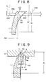
- And thus, the positions of the lens feelers 23A,23B are moved to those of 23A′ ,23B′ when the edge thickness is measured, as shown in Fig. 8. More detailedly, the positions of the
lens feelers 
- Japan patent abstracts vol. 11, No 135 (M-585) [2582], April 28, 1987, and JP-A-61 274 860 (Tokyo Optical Co. Ltd), December 5, 1986, describe a lens shape measuring device and a lens grinding apparatus. On a lens measuring device are provided feelers contacting respectively the front and rear surfaces of a workpiece lens and magnetic encoders for detecting the displacements of the feelers. And movable stages move the feelers along a measure locus on the lens in a predetermined relationship with a supposed edge locus obtained from the shape data of a lens frame of an eye glass frame into which is inserted the lens or the shape data of the lens profiled according to a template. Further, a calculating means provided in the measuring device figures out the edge thickness of lens after mortar working on the basis of the detecting information of the encoders when the feelers are moved on the measured locus.
- The present invention concerns a method for measuring the edge thickness of a spectacle lens comprising the steps of:
inputting an all round radius vector information (ρi, ϑi) of a spectacle frame lens rim for framing said lens (with i=0, 1, 2, 3... N)
obtaining an all round measuring radius vector information (ρi', ϑi) by subtracting a V-groove depth (H) of a grinder (G) from the length (ρi) of the radius vector of said all round radius vector information (ρi, ϑi); and
obtaining an edge thickness information (Δi, ϑi) corresponding to said all round measuring radius vector information (ρi', ϑ i) by measuring a front side refractive position information (fZi, ϑi) and a back side refractive position information (bZi, ϑi) of said lens corresponding to said measuring radius vector information (ρi', ϑi) in order to obtain an edge thickness information (Δi, ϑi) at the grinding position and a V-edge apex position information (kZi, ρi, ϑi) when the edge of said lens is ground with said grinder (G);
characterised by:
a first step of comparing a width (W) of a grinding base of said grinder (G) with said measured edge thickness (Δi) and selectively obtaining a partial measuring radius vector information (ρj', ϑj) (j ≦ i) of said lens where a narrower edge thickness (Δj) than said width (W) is measured;
a second step of obtaining, by presuming that an edge thickness (Δj') in the position of an again measuring radius vector length (ρj'') of a partial and again measuring radius vector information (pj'', ϑj) (with j≦i) for forming a V-edge of said lens by said V-groove of said grinder (G) in a position corresponding to said partial measuring radius vector information (ρj', ϑj) is approximately equal to said edge thickness (Δj), a measuring radius vector length (ρj'') of said partial measuring radius vector (ρj', ϑj) from said partial measuring radius vector information (ρj'', ϑj) (j ≦ i) as follows:
a third step of measuring said front side refractive position information (fZi', ϑi) and said back side refractive position information (bZi', ϑi) of said lens in such a manner as to correspond to said partial and again measuring radius vector information (ρj'', ϑj) which are used for obtaining said V-edge apex position information for grinding the edge of that portion of said lens having said edge thickness (Δj) with said grinder (G).
the present invention concerns also a method for measuring the edge thickness of a spectacle lens comprising the steps of:
inputting all round radius vector information (ρi, ϑi) of a spectacle frame lens rim for framing the lens (with i=0, 1, 2, 3...N);
obtaining all round measuring radius vector information (ρi', ϑi) by subtracting a V-groove depth (H) of a grinder (G) from the length (ρi) of the radius vector of said all round radius vector information (ρi, ϑi); and
obtaining an edge thickness information (Δi, ϑi) corresponding to said all round measuring radius vector information (ρi', ϑi) by measuring a front side refractive position information (fZi, ϑi) and a back side refractive position information (bZi, ϑi) of said lens corresponding to said measuring radius vector information (ρi', ϑi) in order to obtain an edge thickness information (Δi, ϑi) in the grinding position and a V-edge apex position information (kZi, ρi, ϑi) when the edge of said lens is ground with said grinder (G);
characterised by:
a first step of comparing a width (W) of a grinding base of said grinder (G) with an edge thickness (Δi) of said edge thickness information (Δi, ϑi) to obtain partial measuring radius vector information (ρj', ϑj) (with j ≦ i) in which a measured edge thickness (Δj) is less than said width (W) of the grinding base;
a second step of obtaining a compensation value t1 according to the following formula:
a third step of obtaining a compensating radius vector length (τj+1), which corresponds to a length (ρj+1') of the measuring radius vector of said j+1-th partial measuring radius vector information (ρj+1', ϑj+1), according to the following formula:
a fourth step of measuring an edge thickness (Δj+1) by measuring front and back side refractive position information of said lens according to said compensating measuring radius vector information (τj+1, ϑj+1);
a fifth step of comparing said measured edge thickness (Δ j+1) with said preceding measured edge thickness (Δj), and, if said measured edge thickness (Δj+1) is less than said preceding measured edge thickness (Δj), obtaining a compensation value tm according to the following formula:
where Δj+m is an edge thickness of measuring radius vector information (ρj+m', ϑj+m) and


a sixth step of obtaining a compensating radius vector length (τj+m), which corresponds to a length (ρj+m') of the measuring radius vector of said measuring radius vector information (ρj+m', ϑj+m), according to the following formula:
a seventh step of successively measuring front and back side refractive position information of said lens according to said compensating measuring radius vector information (τj+m, ϑj+m). - The advantages of the present invention will be well appreciated upon reading of the following description of the invention when taken in conjunction with the attached drawings with understanding that some modifications, variations and changes of the same could be made by the skilled person in the art to which the invention pertains without departing from the scope of claims appended hereto.
-
- Fig. 1 is a block diagram showing an embodiment of an edge thickness measuring apparatus according to the present invention;
- Fig. 2 is a partly diagrammatic sectional view showing a measuring radius vector, a partial re-measuring radius vector, a lens feeler, and a relation between a measured edge thickness and a grinder's shape, each for describing a first embodiment of an edge measuring method according to the present invention;
- Figs. 3A and 3B are schematic illustrations showing a measuring radius vector, and a relation among the partial re-measuring radius vector and the measured radius vector locus and the partial re-measured radius vector locus, each for explaining the first embodiment of a edge thickness measuring method;
- Fig. 4 is a schematic illustration showing the measuring radius vector, and a relation among the compensated measuring radius vector and the measured radius vector locus and the compensated measured radius vector locus, each for explaining the second embodiment of an edge thickness measuring method;
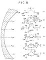
- Fig. 5 is a schematic illustration showing the compensated measured points and the lens feeler at the points, and a relation between the measured edge thickness and the shape of the grinder, each for explaining the second embodiment of an edge thickness measuring method;
- Fig. 6 is a block diagram showing a constitution of a conventional frame shape measuring apparatus;
- Fig. 7 is a block diagram showing a constitution of a conventional edge thickness measuring apparatus;
- Fig. 8 is a schematic illustration showing the measuring radius vector and the lens feeler, and a relation between the measured edge thickness and the shape of the grinder for explaining a conventional edge thickness measuring method;
- Fig. 9 is a schematic diagram showing a relation between the measured edge thickness and the edge shape ground by the grinder according to a conventional edge thickness measuring method.
- The preferred embodiment of the present invention will be described hereinafter with reference to the accompanying drawings.
- Fig. 1 is a block diagram showing a constitution of the embodiment of the edge thickness measuring apparatus according to the present invention. In this embodiment, employed are the identical characters to the same of similar components as the components in the conventional edge thickness measuring apparatus (mentioned above) disclosed in Japanese Patent Application No. SHO 60-115079, in order to avoid duplication of the explanation. A first
arithmetic circuit 32 in Fig. 1 calculates an edge thickness information (Δi, ϑi) from a front and back surface position informations (fZi, ϑi), (bZi, ϑi) of a material lens L as a lens to grind which is detected bydetectors arithmetic circuit 32 also connects with acomparison circuit 41. Thecomparison circuit 41 connects with agrinder shape memory 42 which keeps memorizing an already-known V-edge base width W and a V-edge height H. - The second
arithmetic circuit 43 connects with a lensrim shape memory 18 of a frameshape measuring apparatus 10, thecomparison circuit 41, and thegrinder shape memory 42. The lensrim shape memory 18 memorizes the all round radius vector information (hereinafter referred to as radius vector information, for brevity) (ρi, ϑi) (with i = 0,1,2,3,...N) can be identical with a value measured by the frameshape measuring apparatus 10 such as the conventional apparatus disclosed in Japanese Patent Publication No. SHO 60-115079, or with data memorized in a memory means such as a floppy disk or an IC card, or with data from a framemaker or the agent by the on-line information processing system. - The length ρi of the radius vector of the radius vector information (ρi, ϑi) (with i=0,1,2,3,...N) of the lens rim from the lens
rim shape memory 18 is input in a secondarithmetic circuit 43, which subtracts the V-edge height H memorized in thegrinder shape memory 42 from the length ρi and obtains, as shown in Fig. 2, the length ρi′ of the measuring radius vector of the all round measuring radius vector information (hereinafter referred to as measuring radius vector information) (ρi′, ϑi) by the following formula:
memory 18 and the secondarithmetic circuit 43 act as an input means and an arithmetic means, respectively. - The length (ρi′) obtained is input in a
pulse motor 29. Thepulse motors arithmetic circuit 43, corresponding to the measuring radius vector information (ρi′, ϑi). The driving of thepulse motors lens feelers feelers springs - The moving amount of the
lens feelers detectors arithmetic circuit 32 calculates the Δi of the edge thickness information (Δi, ϑi) of the lens L at the measuring point i on the basis of the information (fZi, ϑi), (bZi, ϑi) as follows:
arithmetic circuit 32 acts as an edge thickness measuring means. - The edge thickness information (Δi, ϑi) (with i=0,1,2,3,...N) calculated by the first
arithmetic circuit 32 is compared with the width (W) of the V-edge base of the V-edge grinder G memorized in thegrinder shape memory 42 by thecomparison circuit 41. And selected is a measuring radius vector having an edge thickness narrower than the width W. Thegrinder shape memory 42 acts as a memorizing means and thecomparison circuit 41 acts as a comparing means. - Fig. 3A shows the lens L as a minus lens. In this case, selected are a partial measuring radius vector information (Δj′, ϑj) (with j=a,a+1,a+2,...b-1,b) which defines the partial measuring locus S₁ of measuring points Pa and Pb, and a partial measuring radius vector information (ρj′, ϑj) (with j=c,c+1,c+2,...d-1,d) which defines the partial measuring locus S₂ of a measuring points Pc and Pd.
- Fig. 3B shows the lens L as a plus lens. In this case, selected are a partial measuring radius vector information (ρj′, ϑj) (with j=c,c+1,c+2,...d-1,d) which defines a partial measuring locus S₂ of measuring points Pc and Pd, and a partial measuring radius vector information (ρj′, ϑj) (with j=g,g+1,g+2,...h-1,h) which defines a partial measuring locus S₄ of measuring points Pg and Ph. And these measuring radius vector lengths ρj′ and edge thicknesses Δj are input into the second
arithmetic circuit 43. - Referring to Fig. 2, if the edge thickness Δj is approximately equal to the edge thicknesses Δj′, the proportion of H to W is:

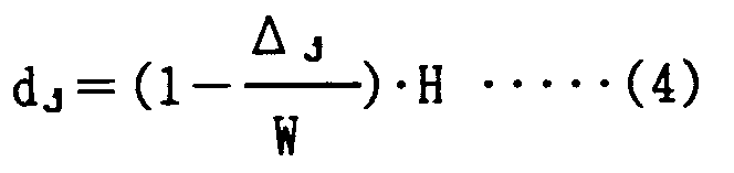
The secondarithmetic circuit 43 obtains the length ρj˝ of a re-measuring radius vector of the partial re-measuring radius vector information (ρj˝, ϑj) by employing the length ρj′ and the above amount dj as follows:
second circuit 43 inputs the re-measuring radius vector length ρj˝ to thepulse motor 25 and the re-measuring radius vector angle ϑj to thepulse motor 29. Thepulse motors lens feelers positions 23A′, 23B′ as shown in Fig. 2. By this movement, thelens feelers - After the measurement of the informations, the calculation of the V-edge apex position, the display of the image, the determination of the radius vector for grinding, and the grinding are each carried out in the circuit (not shown), as disclosed in the above mentioned Japanese Patent Application No. SHO 60-115079.
- Figs. 4 and 5 are schematic illustration showing another edge thickness measuring method with the above mentioned edge thickness measuring apparatus.
- First, all kinds of the length of the radius vector of the radius vector information (ρi, ϑi) (with i=0,1,2,...N) from the lens
rim shape memory 18 are input to the secondarithmetic circuit 43. Thesecond circuit 43 obtains the measuring radius vector information (ρi′, ϑi) (with i=0,1,2,...N) by the formula (1), that is, by subtracting the V-edge height memorized in the grinder shape memory from all (ρi) s. - Second, the second
arithmetic circuit 43 inputs the 0-th measuring radius vector (ρ₀′) in thepulse motor 25 and the 0-th radius vector angle (ϑ₀). The driving of thepulse motors lens feelers lens feelers springs lens feelers detectors arithmetic circuit 32 calculates the Δ₀ of the 0-th edge thickness information (Δ₀, ϑ₀) at the 0-th measuring point P₀ from the informations (fZ₀, ϑ₀), (bZ₀, ϑ₀). The calculation is performed by the following formula similar to the (2) :
first circuit 32 is compared with the V-edge base width W of the V-edge grinder G memorized in thegrinder shape memory 42. - The 0-th edge thickness Δ₀ is broader than the V-edge base width W in the example of Fig. 4. Therefore, the second
arithmetic circuit 43 inputs the length ρ₁′ of the 1st measuring radius, vectorwhich follows the 0-th thickness into thepulse motor 25 and the first radius vector angle ϑ₁, into thepulse motor 29. And thelens feelers - The moving amounts of the
lens feelers detectors arithmetic circuit 32 calculates the Δ₁ of the first edge thickness information (Δ₁, ϑ₁) at the first measuring point P₁ from the information (fZ₁, ϑ₁), (bZ₁, ϑ₁) the same as (2′). - Next, the first edge thickness information (Δ₁, ϑ₁) calculated by the first
arithmetic circuit 32 is compared with the V-edge base width W of the V-edge grinder G memorized in thegrinder shape memory 42 by thecomparison circuit 41. The first edge thickness Δ₁ is broader than the V-edge base width W in the example of Fig. 4. The same procedures are in order followed to the j-th measuring radius vector information (ρj′, ϑj) judged that the edge thickness Δj is narrower than the V-edge base width W. If thecomparison circuit 41 judges that the j-th edge thickness Δj in the j-th measuring radius vector information (ρj′, ϑj) is narrower than the V-edge base width W as shown in Fig. 5(a), the secondarithmetic circuit 43 changes the length ρj+1′ of the (j+1)th measuring radius vector of the (j+1)th measuring radius vector information (ρj+1, ϑj+1) into the first compensated radius vector length τj+1 as shown in Fig. 4. - The first compensated amount t₁ is obtained the same as the formula (4):

where W is the width of the V-edge base of the V-edge grinder G and H is the V-edge height. And the first compensated radius vector length τj+1 is :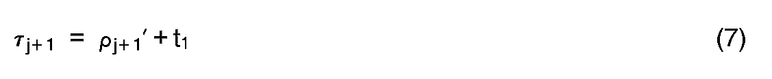
arithmetic circuit 43 inputs the first compensated radius vector length τj+i into thepulse motor 25 and the first compensated radius vector angle ϑj+i (equivalent to the (j+i)th measuring radius vector angle ϑj+i) into thepulse motor 29. And thelens feelers - And then the first
arithmetic circuit 32 obtains the j+1 edge thickness Δj+1 from the front and back surface position informations of the lens L at the first compensated measuring point Tj+1. Thecomparison circuit 41 compares the (j+1)th edge thickness Δj+1 with the j-th edge thickness Δj preceding to Δj+1. - If the (j+1)th edge thickness Δj+1 is narrower than the j-th edge thickness Δj just before the Δj+1 as shown in Fig. 5(b), the second
arithmetic circuit 43 changes the following (j+2)th measuring radius vector length ρj+2′ of the (j+2)th measuring radius vector information (ρj+2′, ϑj+2) into the second compensated radius vector length τj+2 as shown in Fig. 4. - Therefore, the second compensated amount t₂ is obtained the same as the formula (6). That is :

and the second compensated radius vector length τj+2 is:
arithmetic circuit 43 inputs the second compensated radius vector length τj+2 into thepulse motor 25 and the second compensated radius vector angle ϑj+2 (equivalent to the (j+2)th measuring radius vector angle ϑj+2) into the pulse motor29, respectively. Thelens feelers - After the measurement of the front and back surface position informations of the lens L at the second compensated measuring point Tj+2, the first
arithmetic circuit 32 obtains the (j+2)th edge thickness Δj+2. Thecomparison circuit 41 compares the (j+2)th edge thickness Δj+2 with the (j+1)th edge thickness preceding to the (j+2)th thickness. - If the (j+2)th edge thickness Δj+2 is narrower than the preceding (j+1)th edge thickness as shown in Fig. 5(c), the second
arithmetic circuit 43 changes the following (j+3)th measuring radius vector length ρj+3′ of the (j+3)th measuring radius vector information (ρj+3′, ϑj+3) into the third compensated radius vector length τj+3. - And the third compensated amount t₃ is obtained the same as in the formula (6). That is :

where H is the V-edge height of the V-edge grinder G and the Δj+2, Δj+1 are the edge thicknesses. And the third compensated radius vector length τh+3 is :
arithmetic circuit 43 inputs the third compensated radius vector length τj+3 into thepulse motor 25 and the third compensated radius vector angle ϑj+3 (equivalent to the (j+3)th measuring radius vector angle ϑj+3) into the pulse motor29, respectively. And then thelens feelers lens feelers - The front and back surface position information s of the lens L as the third compensated measuring point Tj+3 are measured, and then the first
arithmetic circuit 32 calculates the (j+3)th edge thickness Δj+3. And thecomparison circuit 41 compares the (j+3)th edge thickness Δj+3 with the preceding (j+2)th edge thickness Δj+2. - If the (j+3)th edge thickness Δj+3 is broader than the preceding (j+2)th edge thickness and narrower than the V-edge base width W of the V-edge grinder as shown in Fig. 5(d), the second
arithmetic circuit 43 changes the following (j+4)th measuring radius vector length ρj+4′ of the (j+4) measuring radius vector information (ρj+4', ϑj+4) into the fourth compensated radius vector length τj+4 as shown in Fig. 4. - And the fourth compensated amount t₄ is obtained the same as in the formula (6). That is :

where H is the V-edge height of the V-edge grinder G and the Δj+3, Δj+2 are the edge thicknesses. And the fourth compensated radius vector length τj+4 is :
- The second
arithmetic circuit 43 inputs the fourth compensated radius vector length τj+4 into thepulse motor 25 and the fourth compensated radius vector angle ϑj+4 (equivalent to the (j+4)th measuring radius vector angle ϑj+4) into the pulse motor29, respectively. And then thelens feelers - The front and back surface position information s of the lens L as the fourth compensated measuring point Tj+4 are measured,and then the first
arithmetic circuit 32 calculates the (j+4)th edge thickness Δj+4. - And the
comparison circuit 41 compares the (j+4)th edge thickness Δj+4 with the preceding (j+3)th edge thickness Δj+3. - If the (j+4)th edge thickness Δj+4 is equal to or broader than the V-edge base width W of the V-edge grinder G as shown in Fig. 5(e), the following (j+5)th measuring radius vector information (ρj+5′, ϑj+5) does not need to be changed,and the measuring of the edge thickness at the measuring point Tj+5 on the measuring radius vector locus S as shown in Fig. 5(f) is carried out.
- As mentioned above, in case the measuring edge thickness Δj first turns narrower than the V-edge base width W, the following first compensated measuring radius vector length τj+1 for the (j+1)th measuring radius vector ρj+1′ is changed from the first compensated amount t₁ of the formula (6) to the formula (7):


- Referring to the measurement following to the (j+i)th, the second compensated measuring radius vector length τj+2 and the measuring edge thickness Δj+m-1 preceding to the τj+2 is changed into the (m)th compensated measuring radius vector length τj+m broader than the V-edge base width W.
- The (m)th compensated amount tm in a generalized formula of the formulas (8) through (13) is expressed as follows :

And the (m)th compensated measuring radius vector length τj+m is:
In case the measured edge thickness is narrower than the width W of the V-edge base of the V-edge grinder G as mentioned above, the measurement of the thickness is carried out at the compensated measuring point on the compensated locus S′ shown with the stitch line in Fig. 4. - And thus,the present invention can provide a method and an apparatus for measuring the edge thickness of a spectacle lens, which has an advantage to measure more accurately the edge thickness of the lens narrower than the width of the V-edge base of the V-edge grinder in comparison with the prior art.
Claims (2)
- A method for measuring the edge thickness of a spectacle lens comprising the steps of:
inputting an all round radius vector information (ρi, ϑi) of a spectacle frame lens rim for framing said lens (with i=0, 1, 2, 3... N)
obtaining an all round measuring radius vector information (ρi', ϑi) by subtracting a V-groove depth (H) of a grinder (G) from the length (ρi) of the radius vector of said all round radius vector information (ρi, ϑi) ; and
obtaining an edge thickness information (Δi, ϑi) corresponding to said all round measuring radius vector information (ρi', ϑ i) by measuring a front side refractive position information (fZi, ϑi) and a back side refractive position information (bZi, ϑi) of said lens corresponding to said measuring radius vector information (ρi', ϑi) in order to obtain an edge thickness information (Δi, ϑi) at the grinding position and a V-edge apex position information (kZi, ρi, ϑi) when the edge of said lens is ground with said grinder (G);
characterised by:
a first step of comparing a width (W) of a grinding base of said grinder (G) with said measured edge thickness (Δi) and selectively obtaining a partial measuring radius vector information (ρj', ϑj) (j ≦ i) of said lens where a narrower edge thickness (Δj) than said width (W) is measured;
a second step of obtaining, by presuming that an edge thickness (Δj') in the position of an again measuring radius vector length (ρj'') of a partial and again measuring radius vector information (ρj'', ϑj) (with j≦i) for forming a V-edge of said lens by said V-groove of said grinder (G) in a position corresponding to said partial measuring radius vector information (ρj', ϑj) is approximately equal to said edge thickness (Δj), a measuring radius vector length (ρj'') of said partial measuring radius vector (ρj', ϑj) from said partial measuring radius vector information (ρj'', ϑj) (j ≦ i) as follows:
a third step of measuring said front side refractive position informatin (fZi', ϑi) and said back side refractive position information (bZi', ϑi) of said lens in such a manner as to correspond to said partial and again measuring radius vector information (ρj'', ϑj) which are used for obtaining said V-edge apex position information for grinding the edge of that portion of said lens having said edge thickness (Δj) with said grinder (G). - A method for measuring the edge thickness of a spectacle lens comprising the steps of:
inputting an all round radius vector information (ρi, ϑi) of a spectacle frame lens rim for framing the lens (with i=0, 1, 2, 3...N);
obtaining an all round measuring radius vector information (ρi', ϑi) by subtracting a V-groove depth (H) of a grinder (G) from the length (ρi) of the radius vector of said all round radius vector information (ρi, ϑi); and
obtaining an edge thickness information (Δi, ϑi) corresponding to said all round measuring radius vector information (ρi', ϑi) by measuring a front side refractive position information (fZi, ϑi) and a back side refractive position information (bZi, ϑi) of said lens corresponding to said measuring radius vector information (ρi', ϑi) in order to obtain an edge thickness information (Δi, ϑi) in the grinding position and a V-edge apex position information (kZi, ρi, ϑi) when the edge of said lens is ground with said grinder (G) ;
characterised by:
a first step of comparing a width (W) of a grinding base of said grinder (G) with an edge thickness (Δi) of said edge thickness information (Δi, ϑi) to obtain partial measuring radius vector information (ρj', ϑj) (with j ≦ i) in which a measured edge thickness (Δj) is less than said width (W) of the grinding base;
a second step of obtaining a compensation value t1 according to the following formula:
a third step of obtaining a compensating radius vector length (τj+1), which corresponds to a length (ρj+1') of the measuring radius vector of said j+1-th partial measuring radius vector information (ρj+1', ϑj+1), according to the following formula:
a fourth step of measuring an edge thickness (Δj+1) by measuring front and back side refractive position information of said lens according to said compensating measuring radius vector information (τj+1, ϑj+1);
a fifth step of comparing said measured edge thickness (Δ j+1) with said preceding measured edge thickness (Δj), and, if said measured edge thickness (Δj+1) is less than said preceding measured edge thickness (Δj), obtaining a compensation value tm according to the following formula:
a sixth step of obtaining a compensating radius vector length (τj+m), which corresponds to a length (ρj+m') of the measuring radius vector of said measuring radius vector information (ρj+m', ϑj+m), according to the following formula:
a seventh step of successively measuring front and back side refractive position information of said lens according to said compensating measuring radius vector information (τj+m, ϑj+m).
Applications Claiming Priority (2)
| Application Number | Priority Date | Filing Date | Title |
|---|---|---|---|
| JP1296956A JPH0816611B2 (en) | 1989-11-15 | 1989-11-15 | Method for measuring edge thickness of lens and apparatus therefor |
| JP296956/89 | 1989-11-15 |
Publications (2)
| Publication Number | Publication Date |
|---|---|
| EP0433114A1 EP0433114A1 (en) | 1991-06-19 |
| EP0433114B1 true EP0433114B1 (en) | 1995-09-06 |
Family
ID=17840363
Family Applications (1)
| Application Number | Title | Priority Date | Filing Date |
|---|---|---|---|
| EP19900403223 Expired - Lifetime EP0433114B1 (en) | 1989-11-15 | 1990-11-14 | Method and apparatus for measuring the edge thickness of a spectacle lens |
Country Status (3)
| Country | Link |
|---|---|
| EP (1) | EP0433114B1 (en) |
| JP (1) | JPH0816611B2 (en) |
| DE (1) | DE69022192T2 (en) |
Families Citing this family (9)
| Publication number | Priority date | Publication date | Assignee | Title |
|---|---|---|---|---|
| JPH07509410A (en) * | 1991-07-01 | 1995-10-19 | ヴェルニッケ アンド カンパニー | Manufacturing method for edge-processed eyeglass lenses |
| FR2682058B1 (en) * | 1991-10-04 | 1993-12-10 | Buchmann Optical Engineering | APPARATUS FOR RAISING THE TOPOGRAPHY OF THE CONVEX FACE OF AN OPTICAL GLASS AND MACHINE FOR LAYING AN ADAPTER INCLUDING SUCH AN APPARATUS. |
| DE4200637A1 (en) * | 1992-01-13 | 1993-07-15 | Wernicke & Co Gmbh | DEVICE FOR FACETTING EYE GLASSES |
| DE4208835A1 (en) * | 1992-03-19 | 1993-09-30 | Wernicke & Co Gmbh | Method for shape grinding the circumference of a spectacle lens |
| JPH0829486B2 (en) * | 1993-06-28 | 1996-03-27 | 株式会社タクボ精機製作所 | Lens shape measuring machine |
| DE4417533C2 (en) * | 1994-05-19 | 1996-03-21 | Wernicke & Co Gmbh | Process for CNC-controlled shape grinding of the roof facet of a spectacle lens |
| ES2304353T3 (en) | 1999-08-06 | 2008-10-16 | Hoya Corporation | LENS MANUFACTURING DEVICE AND LENS MANUFACTURING METHOD. |
| FR2894504B1 (en) * | 2005-12-08 | 2009-07-03 | Essilor Int | METHOD FOR PRODUCING A DETOURAGE SETTING OF AN OPHTHALMIC LENS |
| CN112902902A (en) * | 2021-01-19 | 2021-06-04 | 深圳市金天光学科技有限公司 | Lens thickness detection anchor clamps and have thickness detection device of this anchor clamps |
Family Cites Families (3)
| Publication number | Priority date | Publication date | Assignee | Title |
|---|---|---|---|---|
| JPS60123259A (en) * | 1983-12-02 | 1985-07-01 | Nippon Kogaku Kk <Nikon> | Lens peripheral edge machining device |
| JPS629858A (en) * | 1985-03-29 | 1987-01-17 | Tokyo Optical Co Ltd | Lens grinder |
| JPS61274859A (en) * | 1985-05-28 | 1986-12-05 | Tokyo Optical Co Ltd | Lens grinding apparatus |
-
1989
- 1989-11-15 JP JP1296956A patent/JPH0816611B2/en not_active Expired - Lifetime
-
1990
- 1990-11-14 DE DE1990622192 patent/DE69022192T2/en not_active Expired - Fee Related
- 1990-11-14 EP EP19900403223 patent/EP0433114B1/en not_active Expired - Lifetime
Also Published As
| Publication number | Publication date |
|---|---|
| EP0433114A1 (en) | 1991-06-19 |
| JPH0816611B2 (en) | 1996-02-21 |
| JPH03158714A (en) | 1991-07-08 |
| DE69022192T2 (en) | 1996-05-09 |
| DE69022192D1 (en) | 1995-10-12 |
Similar Documents
| Publication | Publication Date | Title |
|---|---|---|
| EP0583915A2 (en) | Spectacle frame processing | |
| US5347762A (en) | Lens periphery processing apparatus, method for obtaining processing data, and lens periphery processing method | |
| US6336057B1 (en) | Lens grinding apparatus | |
| EP0298129B1 (en) | Method and apparatus for processing circumference of spectacle lens | |
| KR101456301B1 (en) | Glasses lens processing equipment | |
| KR101487018B1 (en) | Glasses lens processing equipment | |
| EP0802020A1 (en) | Method and apparatus for grinding the rim of a lens | |
| EP0857540A2 (en) | Lens grinding apparatus | |
| EP0894568B1 (en) | Method and apparatus for grinding eyeglass lenses | |
| EP0433114B1 (en) | Method and apparatus for measuring the edge thickness of a spectacle lens | |
| EP0894567B1 (en) | Method and apparatus for measuring an eyeglass frame and eyeglass lens grinding apparatus using the same | |
| JPH07223153A (en) | Measurement device for frame shape | |
| US6290569B1 (en) | Lens grinding apparatus | |
| JPH0629725B2 (en) | Frame shape measuring device | |
| EP0160985A2 (en) | Method and device for calculating relationship between pre-edged lens and spectacle lens | |
| EP0968790B1 (en) | Eyeglass lens grinding apparatus | |
| CN110293471A (en) | The processing method of a kind of curve surface work pieces and for the equipment in this method | |
| JPH0611467B2 (en) | Lens peripheral processing machine | |
| JPH06175087A (en) | Method and device for inspecting lens for spectacles | |
| EP0379427B1 (en) | Uncut lens judging apparatus for lens grinding machine | |
| EP0143468A2 (en) | Edge grinding method and apparatus | |
| JPH10328991A (en) | Lens grinding and machining device | |
| EP0236182B1 (en) | Lens grinding method and apparatus | |
| EP0297993A2 (en) | Lens grinding apparatus | |
| JPH09117849A (en) | Device for measuring edge thickness of lens to be machined |
Legal Events
| Date | Code | Title | Description |
|---|---|---|---|
| PUAI | Public reference made under article 153(3) epc to a published international application that has entered the european phase |
Free format text: ORIGINAL CODE: 0009012 |
|
| AK | Designated contracting states |
Kind code of ref document: A1 Designated state(s): DE FR GB IT NL |
|
| 17P | Request for examination filed |
Effective date: 19911122 |
|
| 17Q | First examination report despatched |
Effective date: 19930504 |
|
| GRAA | (expected) grant |
Free format text: ORIGINAL CODE: 0009210 |
|
| STAA | Information on the status of an ep patent application or granted ep patent |
Free format text: STATUS: THE PATENT HAS BEEN GRANTED |
|
| AK | Designated contracting states |
Kind code of ref document: B1 Designated state(s): DE FR GB IT NL |
|
| ITF | It: translation for a ep patent filed | ||
| REF | Corresponds to: |
Ref document number: 69022192 Country of ref document: DE Date of ref document: 19951012 |
|
| ET | Fr: translation filed | ||
| PLBE | No opposition filed within time limit |
Free format text: ORIGINAL CODE: 0009261 |
|
| 26N | No opposition filed | ||
| REG | Reference to a national code |
Ref country code: GB Ref legal event code: IF02 |
|
| PGFP | Annual fee paid to national office [announced via postgrant information from national office to epo] |
Ref country code: IT Payment date: 20071126 Year of fee payment: 18 |
|
| PGFP | Annual fee paid to national office [announced via postgrant information from national office to epo] |
Ref country code: GB Payment date: 20071114 Year of fee payment: 18 |
|
| PGFP | Annual fee paid to national office [announced via postgrant information from national office to epo] |
Ref country code: NL Payment date: 20081116 Year of fee payment: 19 Ref country code: DE Payment date: 20081107 Year of fee payment: 19 |
|
| PGFP | Annual fee paid to national office [announced via postgrant information from national office to epo] |
Ref country code: FR Payment date: 20081112 Year of fee payment: 19 |
|
| GBPC | Gb: european patent ceased through non-payment of renewal fee |
Effective date: 20081114 |
|
| PG25 | Lapsed in a contracting state [announced via postgrant information from national office to epo] |
Ref country code: IT Free format text: LAPSE BECAUSE OF NON-PAYMENT OF DUE FEES Effective date: 20081114 |
|
| PG25 | Lapsed in a contracting state [announced via postgrant information from national office to epo] |
Ref country code: GB Free format text: LAPSE BECAUSE OF NON-PAYMENT OF DUE FEES Effective date: 20081114 |
|
| REG | Reference to a national code |
Ref country code: NL Ref legal event code: V1 Effective date: 20100601 |
|
| REG | Reference to a national code |
Ref country code: FR Ref legal event code: ST Effective date: 20100730 |
|
| PG25 | Lapsed in a contracting state [announced via postgrant information from national office to epo] |
Ref country code: FR Free format text: LAPSE BECAUSE OF NON-PAYMENT OF DUE FEES Effective date: 20091130 Ref country code: NL Free format text: LAPSE BECAUSE OF NON-PAYMENT OF DUE FEES Effective date: 20100601 |
|
| PG25 | Lapsed in a contracting state [announced via postgrant information from national office to epo] |
Ref country code: DE Free format text: LAPSE BECAUSE OF NON-PAYMENT OF DUE FEES Effective date: 20100601 |