EP0433002B1 - Magnetic resonance imaging system including active shield gradient coils - Google Patents
Magnetic resonance imaging system including active shield gradient coils Download PDFInfo
- Publication number
- EP0433002B1 EP0433002B1 EP90313412A EP90313412A EP0433002B1 EP 0433002 B1 EP0433002 B1 EP 0433002B1 EP 90313412 A EP90313412 A EP 90313412A EP 90313412 A EP90313412 A EP 90313412A EP 0433002 B1 EP0433002 B1 EP 0433002B1
- Authority
- EP
- European Patent Office
- Prior art keywords
- gradient
- field
- heat shield
- magnetic resonance
- coil means
- Prior art date
- Legal status (The legal status is an assumption and is not a legal conclusion. Google has not performed a legal analysis and makes no representation as to the accuracy of the status listed.)
- Expired - Lifetime
Links
Images


Classifications
-
- G—PHYSICS
- G01—MEASURING; TESTING
- G01R—MEASURING ELECTRIC VARIABLES; MEASURING MAGNETIC VARIABLES
- G01R33/00—Arrangements or instruments for measuring magnetic variables
- G01R33/20—Arrangements or instruments for measuring magnetic variables involving magnetic resonance
- G01R33/28—Details of apparatus provided for in groups G01R33/44 - G01R33/64
- G01R33/38—Systems for generation, homogenisation or stabilisation of the main or gradient magnetic field
- G01R33/381—Systems for generation, homogenisation or stabilisation of the main or gradient magnetic field using electromagnets
- G01R33/3815—Systems for generation, homogenisation or stabilisation of the main or gradient magnetic field using electromagnets with superconducting coils, e.g. power supply therefor
-
- G—PHYSICS
- G01—MEASURING; TESTING
- G01R—MEASURING ELECTRIC VARIABLES; MEASURING MAGNETIC VARIABLES
- G01R33/00—Arrangements or instruments for measuring magnetic variables
- G01R33/20—Arrangements or instruments for measuring magnetic variables involving magnetic resonance
- G01R33/28—Details of apparatus provided for in groups G01R33/44 - G01R33/64
- G01R33/38—Systems for generation, homogenisation or stabilisation of the main or gradient magnetic field
- G01R33/385—Systems for generation, homogenisation or stabilisation of the main or gradient magnetic field using gradient magnetic field coils
-
- G—PHYSICS
- G01—MEASURING; TESTING
- G01R—MEASURING ELECTRIC VARIABLES; MEASURING MAGNETIC VARIABLES
- G01R33/00—Arrangements or instruments for measuring magnetic variables
- G01R33/20—Arrangements or instruments for measuring magnetic variables involving magnetic resonance
- G01R33/28—Details of apparatus provided for in groups G01R33/44 - G01R33/64
- G01R33/42—Screening
- G01R33/421—Screening of main or gradient magnetic field
-
- G—PHYSICS
- G01—MEASURING; TESTING
- G01R—MEASURING ELECTRIC VARIABLES; MEASURING MAGNETIC VARIABLES
- G01R33/00—Arrangements or instruments for measuring magnetic variables
- G01R33/20—Arrangements or instruments for measuring magnetic variables involving magnetic resonance
- G01R33/28—Details of apparatus provided for in groups G01R33/44 - G01R33/64
- G01R33/38—Systems for generation, homogenisation or stabilisation of the main or gradient magnetic field
- G01R33/385—Systems for generation, homogenisation or stabilisation of the main or gradient magnetic field using gradient magnetic field coils
- G01R33/3856—Means for cooling the gradient coils or thermal shielding of the gradient coils
Definitions
- the present invention relates to a magnetic resonance imaging system employing active shield gradient coils for magnetically cancelling a leakage gradient field. More specifically, the present invention is directed to an active shield gradient coil system for reducing eddy current loss occurring in heat-shield members for maintaining the superconducting coil assembly at very low temperatures.
- FIG. 1 shows as conventional magnetic resonance (hereinafter referred to as "MR") imaging apparatuses.
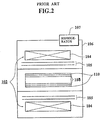
- This conventional MR imaging apparatus comprises a gantry 101 having an imaging chamber in a bore 101A.
- a superconducting magnet 102 around the outer portion thereof for producing a uniform static magnetic field and a gradient field coil 103 for producing a gradient magnetic field to be superimposed with the static magnetic field within the magnet bore 101A.
- the superconducting magnet 102 is so constructed that both a toroidal superconducting coil 104 immersed in a liquid helium bath (not shown in detail), and a heat shield tube 105 for thermally shielding the superconducting coil 104 are contained in an outer vessel 106, the cross-sectional shape of which is toroidal.
- a refrigerator 107 is employed so as to cool the superconducting magnet 5 using helium gas.
- an object under medical examination e.g. a patient (not shown) is inserted into the magnet bore 101A, the static magnetic field produced from the superconducting magnet 102 is uniformly applied particularly to a specific portion (a portion to be imaged) of the patient, and also RF magnetic fields are applied thereto in a direction perpendicular to the application direction of the static magnetic field.
- the MR phenomenon may occur only at the specific slice portion of the object under medical examination and an MR signal (e.g. FID signal and spin echo signal) generated from the specific slice portion is acquired after the application of the RF fields has been accomplished.
- the acquired MR signal is further processed in the image data processor (not shown) by way of e.g.,Fourier transform, whereby tomographic images may be reconstructed and desirable tomographic images may be displayed on a monitor (not shown).
- EP 29 37 23 discloses a magnetic coil system comprising superconductive coils (11, 13) providing a homogenous background magnetic field and normally conductive coils (8) providing a magnetic field gradient.
- a cooled radiation shield (18) of an electrically and thermally conductive material is inserted between the gradient coils (8) and the super conductive coils (11..13).
- the radiation shield (18) comprises superconductive material of a high-temperature superconductor for passive shielding of the magnetic field gradient.
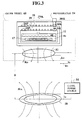
- an active shield gradient coil 110 is employed between the gradient coil 108 and superconducting magnet 102 in order to cancel the above-described leakage field by superimposing a gradient shield field 110 onto the leakage field.
- the field direction of this gradient shield field is opposite to that of the leakage field. Accordingly, employment of the active shield gradient coil 110 can prevent eddy currents from being produced in the heat shield tube 105.
- both the gradient field coil 108 and active shield gradient coil 110 are mounted within a bore (whose typical diameter is approximately 1,000mm) of the outer vessel 106.
- this type of "active shield” causes another problem, that is, since the gradient field coil 108 is positioned in close proximity to the active shield gradient coil 110, a large energising current must be supplied to the active shield gradient coil 110 so as to sufficiently cancel the gradient leakage field leaked from the gradient magnetic field of the active shield gradient coil 110. Therefore, the total power consumption is increased and considerable heat dissipation will occur from the active shield gradient coil 110.
- the diameter of the bore must be enlarged.
- this causes the drawback that the entire dimension of the superconducting magnet 102 becomes large, and therefore a large installation space and higher costs are necessarily required.
- the existing examination room for the MR imaging purpose cannot be used and a new examination room with a higher ceiling height must be prepared for installing such large-sized MR imaging apparatus.
- the diameter of the gradient magnetic coil 108 may be reduced. However, this causes the further difficulty that the patient must be inserted into a narrower space, which then in turn induce claustrophobia.
- slots may be formed in the heat shield tube 105 so as to suppress the eddy current loss.
- the leakage field generated by the gradient field coil 108 may reach the above-described liquid helium container inside the heat shield tube 105 and thus cause further eddy current losses in this liquid helium container.
- the total amount of liquid helium which is evaporated is increased due to this eddy current heat dissipation.
- the present invention has been made in an attempt to solve the above-described drawbacks of the conventional MR imaging systems, and therefore seeks to provide an MR imaging system including an active shield gradient coil capable of being energised with lower power consumption and also capable of effectively reducing eddy current effects.
- the present invention also seeks to provide an MR imaging system capable of reducing total heat dissipation of heat shield members for a superconducting coil system and capable of improving the quality of tomographic images.
- a magnetic resonance imaging apparatus comprises:
- FIG. 3 illustrates the general principles of the invention.
- Pipes “18P” and “19P” for circulating liquid helium are fixed onto heat shield tubes 18 and 19 respectively for maintaining the superconducting coil 17 at very low temperatures.
- These heat shield tubes 18, 19 and pipes 18P, 19P are mechanically coupled to the refrigerator 54 in such a manner that the temperature of the outer heat shield tube 18 is maintained at approximately 80K, whereas the inner heat shield tube 19 is maintained at approximately 20K.
- a gradient field coil assembly 50, an active shield gradient coil assembly 52, and a coil energising power supply 54, are employed in an MR imaging system according to the present invention.
- the gradient coil assembly 50 is connected in series with the active shield gradient coil assembly 52 via the common gradient coil power source 54. Further, a shunt resistor "R S " is connected across the active shield gradient coil assembly 52 so as to shunt the coil energising current "I G ", if required. Thus, a current "I AS " flows through the active shield gradient coil assembly 52, whereas another current “I S” flows through the shunt resistor "R S ".
- the active shield gradient coil assembly 52 is physically positioned apart from the gradient field coil assembly 50 by a distance "D" and housed within the outer vessel 60 so as to maintain the superconducting coil 15 at a very low temperature. That is, this spacing "D" between the active shield gradient coil assembly 52 and the gradient field coil assembly 50 is selected to be considerably larger than that of the convention MR imaging system shown in Figure 2. Accordingly, this active shield gradient coil assembly 52 is positioned in close proximity to the heat shield tubes 18 and 19 used for thermally shielding the superconducting coil 15 within the outer vessel 60.
- the active shield gradient coil assembly 52 is physically spaced apart from the gradient field coil assembly 50, the following specific advantages may be achieved.
- an active shield gradient coil assembly of the type disclosed in, for instance, U.S. Patent No. 4,733,189 is spaced far apart from the gradient field coil assembly and positioned in close proximity to the heat shield tubes for maintaining the superconducting coil at very low temperatures.
- the active shield gradient coil assembly 52 may be positioned in close approximately to one heat shield tube 18 (generally, maintained at 80K) and may be cooled by the existing refrigerator 54 for also cooling the superconducting coil 17.
- Figure 4 schematically illustrates a scanner unit 500 employed in the MR imaging apparatus 1000
- Figure 5 schematically illustrates an arrangement of a gantry unit 600 employed therein.
- a scanner unit 500 of the MR (magnetic resonance) imaging apparatus comprises a couch 2 for supporting a patient "P" and a gantry 4 having an imaging chamber 3. During the MR imaging operation, the couch 2 is moved in the direction of arrow 5, so as to introduce the patient into the imaging chamber.
- MR magnetic resonance
- a superconducting magnet 15 for uniformly producing a static magnetic field in the imaging chamber, and also a gradient field coil 50 for producing a gradient magnetic field to be superimposed with this static magnetic field.
- the superconducting magnet 15 is so constructed that a superconducting coil 17 is installed in the liquid helium tank 12 (see Figure 3) maintained at a very low temperature of about 4K, a second heat shield tube 19K for thermally shielding this superconducting coil 17, which is maintained at a low temperature of about 20K, and a first heat shield tube 18 outside the second heat shield tube 19, for thermally shielding the superconducting coil 17 via the second heat shield tube 19, which is maintained at a low temperature of about 50 to 80 K.
- These superconducting coil 17, first and second heat shield tubes 18 and 19 are contained within an outer vessel 60, whose sectional view is substantially toroidal.
- This toroidal outer vessel 60 is made of reinforced plastics such as FRP (Fiber Reinforced Plastics).
- FRP Fiber Reinforced Plastics
- an active shield gradient coil assembly 52 is contained within the outer vessel 60 and is positioned in close proximity to the first heat shield tube 18 and interposed between the imaging chamber and the first heat shield tube 18 within the outer vessel 60.
- the function of this active shield gradient coil assembly 52 is to magnetically cancel the gradient leakage field produced from the gradient field coil assembly 50 by supplying an energising current through the active shield gradient coil assembly 52, which is opposite the direction to the energising current flowing through the gradient field coil assembly 52.
- the active shield gradient coil 52 is electrically insulated from the first and second heat shield tubes 18 and 19, and thermally connected thereto.
- Figure 6 schematically shows the overall arrangement of the system of the first MR imaging apparatus 1000, from which the relationship between the gradient field coil assembly 50 and active shield gradient coil assembly 52 may be pictorially understood.
- the heat shield tubes 18, 19 and refrigerator 54 are omitted from Figure 6.
- the static magnetic field "H O " is uniformly applied from the superconducting coil 17 to the subject "P" under medical examination inserted into the imaging chamber 3 mounted on the couch 2 in response to a control signal supplied from a static magnetic field controller 20. Further, in response to an RF (radio frequency) current furnished from a transmitter 21, an RF excitation field is applied from an RF coil and also each of the gradient magnetic fields generated from the gradient field coil assembly 52 is superimposed with the static magnetic field.
- This gradient field coil assembly 50 is energised by each of gradient field power sources 23, 24 and 25 for X-axis, Y-axis and Z-axis.
- the above-described gradient active shield field is generated from the active shield gradient coil assembly 52 so as to magnetically cancel the gradient leakage field leaked from the gradient magnetic field.
- an MR signal is produced from a specified portion of the subject "P" and received by the RF coil 22. Thereafter, this MR signal is supplied via a receiver 26 to a signal processor 27.
- the MR signal is image-processed for example by a Fourier transform process so as to reconstruct tomographic images of the subject "P".
- tomographic image data representative of the reconstructed tomographic images are supplied to a display unit 28, whereby the tomograghic images of preselected slices of the subject "P" under medical examination may be monitored on the display unit 28.
- a sequencer 29 is employed to sequentially drive the respective gradient field power sources 23, 24 25, transmitter 21 and receiver 22.
- the active shield gradient coil assembly 52 is positioned close to the first heat shield tube 18 within the outer vessel 60 (see Figure 5), so that the space "D" (see Figure 3) between the gradient field coil assembly 50 and active shield gradient coil assembly 52 is considerably greater than that of the conventional MR imaging apparatus shown in Figure 2.
- this leakage field may be sufficiently cancelled by the relatively small field strength of the active shield field before this leakage field reaches the first and second heat shield tubes 18 and 19. In other words, magnetic cancelling loss occurs when the desirable gradient field is produced becomes small.
- the eddy current occurring in the first and second heat shield tubes 18 and 19 may be sufficiently suppressed even if only a small coil energising current flows through the active shield gradient coil assembly 52. Accordingly, the power capacity of an active shield gradient coil power supply (i.e. the gradient field power sources 23, 24 and 25) may be reduced, as compared with that of a conventional MR imaging apparatus.
- an active shield gradient coil power supply i.e. the gradient field power sources 23, 24 and 25
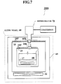
- Figure 7 schematically illustrates a major part of an MR imaging apparatus 2000 according to a second preferred embodiment of the present invention.
- a major feature of the second MR imaging apparatus 2000 is that the active shield gradient coil assembly 52 is contained within a third heat shield tube 65 in the outer vessel 60, and is cooled by the refrigerator 54 which is also used to cool the superconducting magnet 57.
- the entire construction of the second MR imaging apparatus 2000 may be made simple and the manufacturing cost may be reduced.
- the relative position between the gradient field coil 50 and active shield gradient coil 52 may be varied in the first and second MR imaging apparatuses 1000 and 2000, assembly precision may be readily adjusted.
- a conventional MR imaging apparatus having the bore with a small diameter without any active shield gradient coil assembly when the active shield gradient coil assembly is employed within the outer vessel 106 for the superconducting magnet 104, this conventional MR imaging apparatus may be simply modified as an MR imaging apparatus of the present invention without changing the bore diameter.
- the number of heat shield tubes for a refrigerator may be increased to more than 2, so as to provide better insulation, so that a more stable static magnetic field may be produced and thus the S/N ratio of the tomographic image may be further increased.
- the active shield gradient coil assembly is provided within the outer vessel of the superconducting magnet, and therefore the interval between the gradient field coil assembly and active shield gradient coil assembly becomes large, the field strength of the leakage field actually reaching the active shield gradient coil assembly is weakened and only the small current for energising the active shield gradient coil assembly can sufficiently cancel this leakage field.
- the refrigerator for cooling the superconducting magnet may be used also to cool the active shield gradient coil assembly, no additional refrigerator is required.
Description
- The present invention relates to a magnetic resonance imaging system employing active shield gradient coils for magnetically cancelling a leakage gradient field. More specifically, the present invention is directed to an active shield gradient coil system for reducing eddy current loss occurring in heat-shield members for maintaining the superconducting coil assembly at very low temperatures.
- Figure 1 shows as conventional magnetic resonance (hereinafter referred to as "MR") imaging apparatuses. This conventional MR imaging apparatus comprises a
gantry 101 having an imaging chamber in abore 101A. In thisgantry 101, there are provided asuperconducting magnet 102 around the outer portion thereof for producing a uniform static magnetic field and agradient field coil 103 for producing a gradient magnetic field to be superimposed with the static magnetic field within themagnet bore 101A. Thesuperconducting magnet 102 is so constructed that both a toroidalsuperconducting coil 104 immersed in a liquid helium bath (not shown in detail), and aheat shield tube 105 for thermally shielding thesuperconducting coil 104 are contained in anouter vessel 106, the cross-sectional shape of which is toroidal. Arefrigerator 107 is employed so as to cool thesuperconducting magnet 5 using helium gas. - During an MR imaging operation, an object under medical examination, e.g. a patient (not shown) is inserted into the
magnet bore 101A, the static magnetic field produced from thesuperconducting magnet 102 is uniformly applied particularly to a specific portion (a portion to be imaged) of the patient, and also RF magnetic fields are applied thereto in a direction perpendicular to the application direction of the static magnetic field. Furthermore, since the preselected gradient magnetic fields produced from the above-describedgradient field coil 103 are superimposed on the static magnetic field, the MR phenomenon may occur only at the specific slice portion of the object under medical examination and an MR signal (e.g. FID signal and spin echo signal) generated from the specific slice portion is acquired after the application of the RF fields has been accomplished. The acquired MR signal is further processed in the image data processor (not shown) by way of e.g.,Fourier transform, whereby tomographic images may be reconstructed and desirable tomographic images may be displayed on a monitor (not shown). - When the gradient magnetic fields are produced from the gradient
magnetic coil 103, pulsatory leakage fields may occur so that eddy currents will be produced on theheat shield tube 105 for maintaining thesuperconducting magnet 104 at a very low temperature, and furthermore, another pulsatory magnetic field is newly generated by these eddy currents, which will in turn be superimposed with the existing gradient fields. As a result, the resultant gradient magnetic fields cannot provide the required gradient magnetic field, i.e. the required magnetic flux levels and distribution patterns. Accordingly, artifacts may be induced in the tomographic images and the signal level of the MR signal is lowered, resulting in deterioration of image quality. -
EP 29 37 23 discloses a magnetic coil system comprising superconductive coils (11, 13) providing a homogenous background magnetic field and normally conductive coils (8) providing a magnetic field gradient. A cooled radiation shield (18) of an electrically and thermally conductive material is inserted between the gradient coils (8) and the super conductive coils (11..13). - The radiation shield (18) comprises superconductive material of a high-temperature superconductor for passive shielding of the magnetic field gradient.
- To solve the above-described problems caused by the leakage field from the gradient field, a so-called "active shield method" has been proposed.
- For instance, see U.S. Patent No. 4,737,716 issued to Roemer et al on April 12, 1988; U.S. Patent No. 4,733,189 issued to Punchard et al. on March 22, 1988; and U.S. Patent No. 4,794,338 on December 27, 1988.
- A basic idea of such a conventional active shield method will now be summarised with reference to an illustration of Figure 2. It should be noted that the same reference numerals employed in Figure 1 are employed to denote the same or similar components shown in Figure 2.
- As shown in Figure 2, an active
shield gradient coil 110 is employed between thegradient coil 108 andsuperconducting magnet 102 in order to cancel the above-described leakage field by superimposing agradient shield field 110 onto the leakage field. The field direction of this gradient shield field is opposite to that of the leakage field. Accordingly, employment of the activeshield gradient coil 110 can prevent eddy currents from being produced in theheat shield tube 105. In general, both thegradient field coil 108 and activeshield gradient coil 110 are mounted within a bore (whose typical diameter is approximately 1,000mm) of theouter vessel 106. - However, this type of "active shield" causes another problem, that is, since the
gradient field coil 108 is positioned in close proximity to the activeshield gradient coil 110, a large energising current must be supplied to the activeshield gradient coil 110 so as to sufficiently cancel the gradient leakage field leaked from the gradient magnetic field of the activeshield gradient coil 110. Therefore, the total power consumption is increased and considerable heat dissipation will occur from the activeshield gradient coil 110. - In addition, to reduce the heat output from the active
shield gradient coil 110, another cooling means different from the above-describedrefrigerator 107 is additionally required. - As previously described, since two coil energising currents having mutually opposite flow directions must be supplied to the
coils coils coils coils - To separate these
coils superconducting magnet 102 becomes large, and therefore a large installation space and higher costs are necessarily required. In a particular case, the existing examination room for the MR imaging purpose cannot be used and a new examination room with a higher ceiling height must be prepared for installing such large-sized MR imaging apparatus. Alternatively, the diameter of the gradientmagnetic coil 108 may be reduced. However, this causes the further difficulty that the patient must be inserted into a narrower space, which then in turn induce claustrophobia. - Accordingly, the above-described solutions have not yet been realised in the practical MR imaging field.
- Furthermore, if the above-described active shield gradient coil were to be installed in the bore of an existing conventional MR imaging apparatus shown in Figure 1, the present diameter of this bore would have to be increased and therefore huge modification costs and difficulties would be incurred.
- In accordance with another practical solution, slots may be formed in the
heat shield tube 105 so as to suppress the eddy current loss. However, the leakage field generated by thegradient field coil 108 may reach the above-described liquid helium container inside theheat shield tube 105 and thus cause further eddy current losses in this liquid helium container. As a consequence, the total amount of liquid helium which is evaporated is increased due to this eddy current heat dissipation. - The present invention has been made in an attempt to solve the above-described drawbacks of the conventional MR imaging systems, and therefore seeks to provide an MR imaging system including an active shield gradient coil capable of being energised with lower power consumption and also capable of effectively reducing eddy current effects.
- The present invention also seeks to provide an MR imaging system capable of reducing total heat dissipation of heat shield members for a superconducting coil system and capable of improving the quality of tomographic images.
- A magnetic resonance imaging apparatus, according to the present invention, comprises:
- a magnetic resonance imaging unit (600) having an imaging chamber (3) to receive a subject (P) under medical examination;
- a superconducting coil unit contained within an outer vessel which surrounds the imaging chamber,and including superconducting coil means for uniformly producing a static magnetic field to be applied to the subject, and at least one heat shield member for thermally shielding the superconducting coil means;
- gradient field coil means provided between the outer vessel and imaging chamber, for producing a gradient magnetic field so as to be superimposed on the static magnetic field, characterised by:
- active shield gradient coil means for producing a gradient shield, and disposed within the outer vessel in such a manner that the active shield gradient coil means is thermally coupled to the heat shield member and magnetically coupled with a leakage field from the gradient magnetic field of the gradient field coil means, whereby the leakage field is magnetically cancelled by the gradient shield field and substantially no eddy current is produced in the heat shield member.
- Some embodiments of the present invention will now be described by way of example with reference to the accompanying drawings, in which:
- Figures 1 and 2 are illustrations of two typical conventional MR imaging systems;
- Figure 3 is a diagrammatic illustration of the principles present invention;
- Figure 4 schematically represents a
scanner unit 500 employed in anMR imaging apparatus 1000 according to a first preferred embodiment of the present invention; - Figure 5 schematically represents a
gantry unit 600 employed in the firstMR imaging apparatus 1000; - Figure 6 schematically illustrates an overall system of the first
MR imaging apparatus 1000; and, - Figure 7 pictorially illustrates an arrangement of the active shield gradient coil assembly employed in another MR imaging apparatus according to a second preferred embodiment.
- Figure 3 illustrates the general principles of the invention.
- Pipes "18P" and "19P" for circulating liquid helium are fixed onto
heat shield tubes superconducting coil 17 at very low temperatures. Theseheat shield tubes pipes refrigerator 54 in such a manner that the temperature of the outerheat shield tube 18 is maintained at approximately 80K, whereas the innerheat shield tube 19 is maintained at approximately 20K. - A gradient
field coil assembly 50, an active shieldgradient coil assembly 52, and a coilenergising power supply 54, are employed in an MR imaging system according to the present invention. - The
gradient coil assembly 50 is connected in series with the active shieldgradient coil assembly 52 via the common gradientcoil power source 54. Further, a shunt resistor "RS" is connected across the active shieldgradient coil assembly 52 so as to shunt the coil energising current "IG", if required. Thus, a current "IAS" flows through the active shieldgradient coil assembly 52, whereas another current "IS" flows through the shunt resistor "RS". - In accordance with a major feature of the present invention, the active shield
gradient coil assembly 52 is physically positioned apart from the gradientfield coil assembly 50 by a distance "D" and housed within theouter vessel 60 so as to maintain thesuperconducting coil 15 at a very low temperature. That is, this spacing "D" between the active shieldgradient coil assembly 52 and the gradientfield coil assembly 50 is selected to be considerably larger than that of the convention MR imaging system shown in Figure 2. Accordingly, this active shieldgradient coil assembly 52 is positioned in close proximity to theheat shield tubes superconducting coil 15 within theouter vessel 60. - Since the active shield
gradient coil assembly 52 is physically spaced apart from the gradientfield coil assembly 50, the following specific advantages may be achieved. - First, since only a part of the gradient leakage field "HGL" produced from the gradient
field coil assembly 50 reaches the active shieldgradient coil assembly 52, the field strength of this gradient leakage field portion becomes quite small. As a result, the magnetic field strength of the active shield field "HGS" used for magnetically cancelling this small field strength of the gradient leakage field "HGL", can also be small. - Moreover, even if a part of the gradient leakage field "HGL" cannot be magnetically cancelled by this active shield "HGS" and reaches the
heat shield tubes heat shield tubes liquid helium tank 12, as compared with the above-described conventional MR imaging apparatus shown in Figure 2. - Consequently, as will be apparent from Figure 3, the required energising current "IAS" for the active
field coil assembly 52 to sufficiently and magnetically cancel the gradient leakage field "HGL" intersecting this active shieldgradient coil assembly 52, is quite small as compared within the conventional MR imaging apparatus shown in Figure 2. As a consequence, since the gradient leakage field "HGL" actually intersecting this active shieldgradient coil assembly 52 may be sufficiently cancelled, an eddy current loss caused by the uncancelled gradient leakage field becomes very small, as compared with the conventional MR imaging apparatus. - The relationship between the coil energising currents is as follows:


- In summary, an active shield gradient coil assembly of the type disclosed in, for instance, U.S. Patent No. 4,733,189, is spaced far apart from the gradient field coil assembly and positioned in close proximity to the heat shield tubes for maintaining the superconducting coil at very low temperatures.
- Preferably, the active shield
gradient coil assembly 52 may be positioned in close approximately to one heat shield tube 18 (generally, maintained at 80K) and may be cooled by the existingrefrigerator 54 for also cooling thesuperconducting coil 17. - Referring now to Figures 4 and 5, a more complete construction of an
MR imaging apparatus 1000 according to a first preferred embodiment of the present invention will be described. - Figure 4 schematically illustrates a
scanner unit 500 employed in theMR imaging apparatus 1000, and Figure 5 schematically illustrates an arrangement of agantry unit 600 employed therein. - As represent in Figure 4, a
scanner unit 500 of the MR (magnetic resonance) imaging apparatus according to a preferred embodiment of the present invention, comprises acouch 2 for supporting a patient "P" and a gantry 4 having animaging chamber 3. During the MR imaging operation, thecouch 2 is moved in the direction ofarrow 5, so as to introduce the patient into the imaging chamber. - As shown in Figure 5, there are provided around a peripheral portion within the gantry 4, a
superconducting magnet 15 for uniformly producing a static magnetic field in the imaging chamber, and also agradient field coil 50 for producing a gradient magnetic field to be superimposed with this static magnetic field. Thesuperconducting magnet 15 is so constructed that asuperconducting coil 17 is installed in the liquid helium tank 12 (see Figure 3) maintained at a very low temperature of about 4K, a second heat shield tube 19K for thermally shielding thissuperconducting coil 17, which is maintained at a low temperature of about 20K, and a firstheat shield tube 18 outside the secondheat shield tube 19, for thermally shielding thesuperconducting coil 17 via the secondheat shield tube 19, which is maintained at a low temperature of about 50 to 80 K. Thesesuperconducting coil 17, first and secondheat shield tubes outer vessel 60, whose sectional view is substantially toroidal. This toroidalouter vessel 60 is made of reinforced plastics such as FRP (Fiber Reinforced Plastics). The interior of theouter vessel 60 is evacuated and kept at a low pressure in order to shield externally transferred heat. - As the major feature of the present invention, an active shield
gradient coil assembly 52 is contained within theouter vessel 60 and is positioned in close proximity to the firstheat shield tube 18 and interposed between the imaging chamber and the firstheat shield tube 18 within theouter vessel 60. As previously explained, the function of this active shieldgradient coil assembly 52 is to magnetically cancel the gradient leakage field produced from the gradientfield coil assembly 50 by supplying an energising current through the active shieldgradient coil assembly 52, which is opposite the direction to the energising current flowing through the gradientfield coil assembly 52. As a result, since the gradient leakage field may be substantially and magnetically cancelled by the gradient active shield field of this active shieldgradient coil assembly 52 before this leakage field reaches the first and secondheat shield tubes heat shield tubes - It should be noted that the active
shield gradient coil 52 is electrically insulated from the first and secondheat shield tubes - Figure 6 schematically shows the overall arrangement of the system of the first
MR imaging apparatus 1000, from which the relationship between the gradientfield coil assembly 50 and active shieldgradient coil assembly 52 may be pictorially understood. For the sake of simplicity, theheat shield tubes refrigerator 54 are omitted from Figure 6. - An overall imaging operation of the first
MR imaging apparatus 1000 will now be described. - In the first
MR imaging system 1000 Shown in Figure 6, the static magnetic field "HO" is uniformly applied from thesuperconducting coil 17 to the subject "P" under medical examination inserted into theimaging chamber 3 mounted on thecouch 2 in response to a control signal supplied from a staticmagnetic field controller 20. Further, in response to an RF (radio frequency) current furnished from atransmitter 21, an RF excitation field is applied from an RF coil and also each of the gradient magnetic fields generated from the gradientfield coil assembly 52 is superimposed with the static magnetic field. This gradientfield coil assembly 50 is energised by each of gradientfield power sources gradient coil assembly 52 so as to magnetically cancel the gradient leakage field leaked from the gradient magnetic field. - Under the above-described conditions, an MR signal is produced from a specified portion of the subject "P" and received by the
RF coil 22. Thereafter, this MR signal is supplied via areceiver 26 to asignal processor 27. In thissignal processor 27, the MR signal is image-processed for example by a Fourier transform process so as to reconstruct tomographic images of the subject "P". Thus, tomographic image data representative of the reconstructed tomographic images are supplied to adisplay unit 28, whereby the tomograghic images of preselected slices of the subject "P" under medical examination may be monitored on thedisplay unit 28. Asequencer 29 is employed to sequentially drive the respective gradientfield power sources transmitter 21 andreceiver 22. - As previously described, in accordance with the first
MR imaging apparatus 1000, the active shieldgradient coil assembly 52 is positioned close to the firstheat shield tube 18 within the outer vessel 60 (see Figure 5), so that the space "D" (see Figure 3) between the gradientfield coil assembly 50 and active shieldgradient coil assembly 52 is considerably greater than that of the conventional MR imaging apparatus shown in Figure 2. As a consequence, since the field strength of the leakage field reaching the active shieldgradient coil assembly 52 is relatively small, as compared with that of the conventional MR imaging apparatus, this leakage field may be sufficiently cancelled by the relatively small field strength of the active shield field before this leakage field reaches the first and secondheat shield tubes - As a result, the eddy current occurring in the first and second
heat shield tubes gradient coil assembly 52. Accordingly, the power capacity of an active shield gradient coil power supply (i.e. the gradientfield power sources - Figure 7 schematically illustrates a major part of an
MR imaging apparatus 2000 according to a second preferred embodiment of the present invention. - As apparent from Figure 7, a major feature of the second
MR imaging apparatus 2000 is that the active shieldgradient coil assembly 52 is contained within a thirdheat shield tube 65 in theouter vessel 60, and is cooled by therefrigerator 54 which is also used to cool the superconducting magnet 57. - Since no separate refrigerator is required for cooling the
coil assembly 52, the entire construction of the secondMR imaging apparatus 2000 may be made simple and the manufacturing cost may be reduced. - The present invention also has various other advantages
- For instance, since the relative position between the
gradient field coil 50 and activeshield gradient coil 52 may be varied in the first and secondMR imaging apparatuses outer vessel 106 for thesuperconducting magnet 104, this conventional MR imaging apparatus may be simply modified as an MR imaging apparatus of the present invention without changing the bore diameter. - Furthermore, the number of heat shield tubes for a refrigerator may be increased to more than 2, so as to provide better insulation, so that a more stable static magnetic field may be produced and thus the S/N ratio of the tomographic image may be further increased.
- While the present invention has been described in detail, since the active shield gradient coil assembly is provided within the outer vessel of the superconducting magnet, and therefore the interval between the gradient field coil assembly and active shield gradient coil assembly becomes large, the field strength of the leakage field actually reaching the active shield gradient coil assembly is weakened and only the small current for energising the active shield gradient coil assembly can sufficiently cancel this leakage field.
- Since the refrigerator for cooling the superconducting magnet may be used also to cool the active shield gradient coil assembly, no additional refrigerator is required.
Claims (6)
- A magnetic resonance imaging apparatus (1000;2000) comprising:a magnetic resonance imaging unit (600) having an imaging chamber (3) thereof, to receive a subject (P) under medical examination;a superconducting coil unit (15) contained within an outer vessel (60) which surrounds the imaging chamber (3), and including superconducting coil means (17) for uniformly producing a static magnetic field to be applied to the subject (P), and at least one heat shield member (18) for thermally shielding the superconducting coil means (17);gradient field coil means (50) provided between the outer vessel (60) and imaging chamber (3), for producing a gradient magnetic field so as to be superimposed on the static magnetic field, characterised by:active shield gradient coil means (52) for producing a gradient shield (HGS), and disposed within the outer vessel (60) in such a manner that the active shield gradient coil means (52) is thermally coupled to the heat shield member (18) and magnetically coupled with a leakage field (HGL) from the gradient magnetic field of the gradient field coil means (50), whereby the leakage field (HGL) is magnetically cancelled by the gradient shield field (HGS) and substantially no eddy current is produced in the heat shield member (18).
- A magnetic resonance imaging apparatus (1000;2000) as claimed in claim 1, wherein said active shield gradient coil means (52) is positioned in close proximity to the heat shield member (18) within the outer vessel (60).
- A magnetic resonance imaging apparatus (1000;2000) according to claim 1 or claim 2 further comprising:
a second heat shield member (19) inside the heat shield member (18), for thermally enclosing said superconducting coil means (17). - A magnetic resonance imaging apparatus (1000) according to claim 3 further comprising:
a refrigeration unit (54) for cooling both of said heat shield members (18;19) to predetermined lower temperatures than the ambient temperature of the outer vessel (60). - A magnetic resonance imaging apparatus (2000) according to claim 3 further comprising:a third heat shield member (65) for enclosing both of said second heat shield member (19) and said active shield gradient coil means (52) within the outer vessel (60); and,a refrigerator (54) for cooling at least both of said first heat shield member (18) and said active shield gradient coil means (52) to preselected lower temperatures than an ambient temperature of the outer vessel (60).
- A magnetic resonance imaging apparatus (1000;2000) as claimed in claim 1, wherein said heat shield member (18) is a tube.
Applications Claiming Priority (2)
| Application Number | Priority Date | Filing Date | Title |
|---|---|---|---|
| JP318942/89 | 1989-12-11 | ||
| JP1318942A JPH03182232A (en) | 1989-12-11 | 1989-12-11 | Magnetic resonance imaging device |
Publications (3)
| Publication Number | Publication Date |
|---|---|
| EP0433002A2 EP0433002A2 (en) | 1991-06-19 |
| EP0433002A3 EP0433002A3 (en) | 1991-11-06 |
| EP0433002B1 true EP0433002B1 (en) | 1996-09-04 |
Family
ID=18104711
Family Applications (1)
| Application Number | Title | Priority Date | Filing Date |
|---|---|---|---|
| EP90313412A Expired - Lifetime EP0433002B1 (en) | 1989-12-11 | 1990-12-11 | Magnetic resonance imaging system including active shield gradient coils |
Country Status (4)
| Country | Link |
|---|---|
| US (1) | US5132618A (en) |
| EP (1) | EP0433002B1 (en) |
| JP (1) | JPH03182232A (en) |
| DE (1) | DE69028379T2 (en) |
Families Citing this family (36)
| Publication number | Priority date | Publication date | Assignee | Title |
|---|---|---|---|---|
| US5289128A (en) * | 1992-03-27 | 1994-02-22 | Picker International, Inc. | Superconducting gradient shield coils |
| US5280247A (en) * | 1992-03-27 | 1994-01-18 | Picker International, Inc. | Filamentary cold shield for superconducting magnets |
| US5296810A (en) * | 1992-03-27 | 1994-03-22 | Picker International, Inc. | MRI self-shielded gradient coils |
| DE4101481C2 (en) * | 1991-01-19 | 1994-01-13 | Bruker Analytische Messtechnik | Arrangement for compensating external magnetic field disturbances in a nuclear magnetic resonance spectrometer with a superconducting magnetic coil |
| GB2257521B (en) * | 1991-07-04 | 1995-10-04 | Magnex Scient Limited | Electromagnets |
| US5192911A (en) * | 1991-08-07 | 1993-03-09 | Varian Associates, Inc. | NMR probe incorporating RF shielding of sample |
| US5278502A (en) * | 1991-09-13 | 1994-01-11 | General Electric Company | Refrigerated superconducting MR magnet with integrated cryogenic gradient coils |
| DE4142263C2 (en) * | 1991-12-20 | 1994-03-24 | Bruker Analytische Messtechnik | Gradient coil system |
| US5489848A (en) * | 1992-09-08 | 1996-02-06 | Kabushiki Kaisha Toshiba | Magnetic resonance imaging apparatus |
| US5554929A (en) * | 1993-03-12 | 1996-09-10 | Doty Scientific, Inc. | Crescent gradient coils |
| US7092352B2 (en) * | 1993-07-23 | 2006-08-15 | Aquity, Llc | Cancellation systems for multicarrier transceiver arrays |
| US5523526A (en) * | 1993-07-23 | 1996-06-04 | Genesis Magnetics Corporation | Sustaining devices for stringed musical instruments |
| US6208135B1 (en) | 1994-07-22 | 2001-03-27 | Steve J. Shattil | Inductive noise cancellation circuit for electromagnetic pickups |
| US5539367A (en) * | 1994-05-02 | 1996-07-23 | General Electric Company | Superconducting gradient shields in magnetic resonance imaging magnets |
| US5701075A (en) * | 1996-01-04 | 1997-12-23 | General Electric Company | Magnetic resonance imaging shimming by superconducting gradient shield |
| JP3654463B2 (en) * | 1996-03-29 | 2005-06-02 | 株式会社日立メディコ | Magnetic resonance imaging system |
| US6100692A (en) * | 1998-01-05 | 2000-08-08 | Picker International, Inc. | Gradient coil set with a finite shield current |
| US6236203B1 (en) | 1998-09-28 | 2001-05-22 | Picker International, Inc. | Super shielding of finite length structures in open magnetic and electric systems |
| JP2002528204A (en) * | 1998-10-28 | 2002-09-03 | コーニンクレッカ フィリップス エレクトロニクス エヌ ヴィ | MRI apparatus with eddy current shield mechanically integrated in gradient system |
| US6049207A (en) * | 1998-11-25 | 2000-04-11 | Picker International, Inc. | Double-duty gradient coil assembly having two primary gradient coil sets and a common screening coil set |
| US6278275B1 (en) | 1999-10-18 | 2001-08-21 | Picker International, Inc. | Gradient coil set with non-zero first gradient field vector derivative |
| US6278276B1 (en) | 1999-11-16 | 2001-08-21 | Picker International, Inc. | Phased array gradient coil set with an off center gradient field sweet spot |
| US6262576B1 (en) | 1999-11-16 | 2001-07-17 | Picker International, Inc. | Phased array planar gradient coil set for MRI systems |
| US6342787B1 (en) | 2000-11-22 | 2002-01-29 | Philips Medical Systems (Cleveland) | Real-time multi-axis gradient distortion correction using an interactive shim set |
| JP3907182B2 (en) * | 2002-05-07 | 2007-04-18 | 株式会社東芝 | Magnetic resonance imaging system |
| US7170377B2 (en) * | 2004-07-28 | 2007-01-30 | General Electric Company | Superconductive magnet including a cryocooler coldhead |
| US7352183B2 (en) * | 2006-06-22 | 2008-04-01 | General Electric Company | Method and apparatus for locally shielding MR superconducting magnet coil |
| CN101889213A (en) * | 2007-12-10 | 2010-11-17 | 皇家飞利浦电子股份有限公司 | Superconducting magnet system with cooling system |
| GB2455720B (en) * | 2007-12-18 | 2010-01-06 | Siemens Magnet Technology Ltd | Re-workable pressure vessels for superconducting magnet arrangements |
| US9389291B2 (en) * | 2009-11-27 | 2016-07-12 | Hitachi Medical Corporation | Gradient coil, magnetic resonance imaging device, and method for designing coil pattern |
| JP5539022B2 (en) * | 2010-05-25 | 2014-07-02 | 三菱電機株式会社 | Conduction cooled superconducting magnet system |
| CN102736044A (en) * | 2012-07-19 | 2012-10-17 | 南京麦菲电子科技有限公司 | Method for fabricating gradient coil of superconducting magnetic resonance imaging device |
| JP2015079846A (en) * | 2013-10-17 | 2015-04-23 | 株式会社日立製作所 | Superconducting magnetic device |
| CN109239629B (en) * | 2018-08-30 | 2021-08-10 | 上海联影医疗科技股份有限公司 | Gradient coil assembly and method for generating gradient magnetic field |
| JP7465562B2 (en) | 2018-09-12 | 2024-04-11 | ザ リージェンツ オブ ザ ユニバーシティ オブ コロラド,ア ボディー コーポレイト | Cryogenically cooled vacuum chamber radiation shield for cryogenic experiments and ultra-high vacuum (XHV) conditions |
| CN115047388B (en) * | 2021-03-09 | 2023-10-17 | 宁波健信超导科技股份有限公司 | Manufacturing and assembling method of magnetic resonance imaging gradient coil |
Family Cites Families (12)
| Publication number | Priority date | Publication date | Assignee | Title |
|---|---|---|---|---|
| JPS61113218A (en) * | 1984-11-07 | 1986-05-31 | Mitsubishi Electric Corp | Superconductive magnet |
| US4737716A (en) * | 1986-02-06 | 1988-04-12 | General Electric Company | Self-shielded gradient coils for nuclear magnetic resonance imaging |
| US4733189A (en) * | 1986-06-03 | 1988-03-22 | Massachusetts Institute Of Technology | Magnetic resonance imaging systems |
| JPH0687444B2 (en) * | 1986-12-22 | 1994-11-02 | 株式会社東芝 | Magnetic resonance imager |
| US4771256A (en) * | 1987-04-02 | 1988-09-13 | General Electric Company | Integral shield for mr magnet |
| US4876510A (en) * | 1987-06-04 | 1989-10-24 | Siemens Aktiengesellschaft | Apparatus for nuclear spin tomography having superconducting base field magnetic coils and a radiation shield |
| US4783628A (en) * | 1987-08-14 | 1988-11-08 | Houston Area Research Center | Unitary superconducting electromagnet |
| US4881035A (en) * | 1987-11-24 | 1989-11-14 | Siemens Aktiengesellschaft | Magnetic structural arrangement of an installation for nuclear magnetic resonance tomography with superconducting background field coils and normal-conducting gradient coils |
| US4794338A (en) * | 1987-11-25 | 1988-12-27 | General Electric Company | Balanced self-shielded gradient coils |
| JPH01243503A (en) * | 1988-03-25 | 1989-09-28 | Toshiba Corp | Static magnetic field magnet for magnetic resonance imaging device |
| JPH0687447B2 (en) * | 1988-07-27 | 1994-11-02 | 三菱電機株式会社 | Superconducting magnet device |
| IL89743A0 (en) * | 1989-03-26 | 1989-09-28 | Elscint Ltd | Compact shielded gradient coil system |
-
1989
- 1989-12-11 JP JP1318942A patent/JPH03182232A/en active Pending
-
1990
- 1990-12-10 US US07/624,553 patent/US5132618A/en not_active Expired - Lifetime
- 1990-12-11 EP EP90313412A patent/EP0433002B1/en not_active Expired - Lifetime
- 1990-12-11 DE DE69028379T patent/DE69028379T2/en not_active Expired - Fee Related
Also Published As
| Publication number | Publication date |
|---|---|
| US5132618A (en) | 1992-07-21 |
| DE69028379D1 (en) | 1996-10-10 |
| JPH03182232A (en) | 1991-08-08 |
| EP0433002A3 (en) | 1991-11-06 |
| EP0433002A2 (en) | 1991-06-19 |
| DE69028379T2 (en) | 1997-01-23 |
Similar Documents
| Publication | Publication Date | Title |
|---|---|---|
| EP0433002B1 (en) | Magnetic resonance imaging system including active shield gradient coils | |
| US5289128A (en) | Superconducting gradient shield coils | |
| US5410287A (en) | Open MRI magnet with uniform magnetic field | |
| US5406204A (en) | Integrated MRI gradient coil and RF screen | |
| US5677630A (en) | Planar superconducting MRI magnet | |
| US5489848A (en) | Magnetic resonance imaging apparatus | |
| US6157276A (en) | MRI magnet assembly with non-conductive inner wall | |
| US5349297A (en) | Combined self shielded gradient coil and shimset | |
| EP0817211B1 (en) | Superconducting magnet device and magnetic resonance imaging device using the same | |
| US5721523A (en) | Compact MRI superconducting magnet | |
| US5596303A (en) | Superconductive magnet system with low and high temperature superconductors | |
| US5361054A (en) | Magnet system | |
| JPH0576592B2 (en) | ||
| EP0334382B1 (en) | Magnet apparatus for use in magnetic resonance imaging system | |
| US6965236B2 (en) | MRI system utilizing supplemental static field-shaping coils | |
| US5568110A (en) | Closed MRI magnet having reduced length | |
| EP0167243A2 (en) | Magnetic structure | |
| JP2002143124A (en) | Magnetic resonance imaging equipment | |
| EP0332176B1 (en) | Magnet apparatus for use in magnetic resonance imaging system | |
| US5594401A (en) | Closed superconductive magnet with uniform imaging volume | |
| US5521571A (en) | Open MRI magnet with uniform imaging volume | |
| JP2592920B2 (en) | Superconducting magnet for magnetic resonance imaging | |
| JPH0582333A (en) | Nuclear magnetic resonance diagnosing apparatus | |
| EP0859240A1 (en) | Magnet system for magnetic resonance imaging and spectroscopy | |
| JPH0969426A (en) | Superconductive magnet |
Legal Events
| Date | Code | Title | Description |
|---|---|---|---|
| PUAI | Public reference made under article 153(3) epc to a published international application that has entered the european phase |
Free format text: ORIGINAL CODE: 0009012 |
|
| 17P | Request for examination filed |
Effective date: 19901221 |
|
| AK | Designated contracting states |
Kind code of ref document: A2 Designated state(s): DE GB |
|
| PUAL | Search report despatched |
Free format text: ORIGINAL CODE: 0009013 |
|
| AK | Designated contracting states |
Kind code of ref document: A3 Designated state(s): DE GB |
|
| 17Q | First examination report despatched |
Effective date: 19950116 |
|
| GRAH | Despatch of communication of intention to grant a patent |
Free format text: ORIGINAL CODE: EPIDOS IGRA |
|
| GRAH | Despatch of communication of intention to grant a patent |
Free format text: ORIGINAL CODE: EPIDOS IGRA |
|
| GRAA | (expected) grant |
Free format text: ORIGINAL CODE: 0009210 |
|
| AK | Designated contracting states |
Kind code of ref document: B1 Designated state(s): DE GB |
|
| REF | Corresponds to: |
Ref document number: 69028379 Country of ref document: DE Date of ref document: 19961010 |
|
| PLBE | No opposition filed within time limit |
Free format text: ORIGINAL CODE: 0009261 |
|
| STAA | Information on the status of an ep patent application or granted ep patent |
Free format text: STATUS: NO OPPOSITION FILED WITHIN TIME LIMIT |
|
| 26N | No opposition filed | ||
| REG | Reference to a national code |
Ref country code: GB Ref legal event code: IF02 |
|
| PGFP | Annual fee paid to national office [announced via postgrant information from national office to epo] |
Ref country code: GB Payment date: 20071205 Year of fee payment: 18 |
|
| PGFP | Annual fee paid to national office [announced via postgrant information from national office to epo] |
Ref country code: DE Payment date: 20071206 Year of fee payment: 18 |
|
| GBPC | Gb: european patent ceased through non-payment of renewal fee |
Effective date: 20081211 |
|
| PG25 | Lapsed in a contracting state [announced via postgrant information from national office to epo] |
Ref country code: DE Free format text: LAPSE BECAUSE OF NON-PAYMENT OF DUE FEES Effective date: 20090701 |
|
| PG25 | Lapsed in a contracting state [announced via postgrant information from national office to epo] |
Ref country code: GB Free format text: LAPSE BECAUSE OF NON-PAYMENT OF DUE FEES Effective date: 20081211 |