EP0432852A1 - Starting device for a two-pole single-phase synchronous motor with permanent magnet rotor - Google Patents
Starting device for a two-pole single-phase synchronous motor with permanent magnet rotor Download PDFInfo
- Publication number
- EP0432852A1 EP0432852A1 EP90203243A EP90203243A EP0432852A1 EP 0432852 A1 EP0432852 A1 EP 0432852A1 EP 90203243 A EP90203243 A EP 90203243A EP 90203243 A EP90203243 A EP 90203243A EP 0432852 A1 EP0432852 A1 EP 0432852A1
- Authority
- EP
- European Patent Office
- Prior art keywords
- rotor
- load
- play
- angle
- positive
- Prior art date
- Legal status (The legal status is an assumption and is not a legal conclusion. Google has not performed a legal analysis and makes no representation as to the accuracy of the status listed.)
- Granted
Links
Images


Classifications
-
- H—ELECTRICITY
- H02—GENERATION; CONVERSION OR DISTRIBUTION OF ELECTRIC POWER
- H02K—DYNAMO-ELECTRIC MACHINES
- H02K7/00—Arrangements for handling mechanical energy structurally associated with dynamo-electric machines, e.g. structural association with mechanical driving motors or auxiliary dynamo-electric machines
- H02K7/10—Structural association with clutches, brakes, gears, pulleys or mechanical starters
- H02K7/118—Structural association with clutches, brakes, gears, pulleys or mechanical starters with starting devices
- H02K7/1185—Structural association with clutches, brakes, gears, pulleys or mechanical starters with starting devices with a mechanical one-way direction control, i.e. with means for reversing the direction of rotation of the rotor
Definitions
- the invention relates to a starting aid for a two-pole single-phase synchronous motor with a permanent-magnet rotor and a magnetic adhesive torque, which has positive and negative values seen over one revolution with the resulting stable and unstable rest positions, the stable rest positions being offset by the asymmetry angle y in the positive direction are offset from the middle field direction of the stator field and a critical adhesive moment M klkr is effective in the parallel position of the stator field and rotor field, consisting of a torsional backlash between a driving part connected to the rotor and a load part and a direction lock, the backlash angle E of the backlash between the load side and motor-side components, around which the components can rotate uncoupled against each other, are limited in the positive and negative direction of rotation by means of positive and negative game walls of the rotor or load-side components.
- the negative load and rotor play walls are those that are in operation in the negative direction of rotation of the rotor, the positive load and rotor play walls are present when the rotor has passed through the game in the positive direction.
- This definition also applies to the arrangements described below with gears, in which the play means are attached to the second gear stage, the direction of rotation of which is reversed from that of the rotor.
- the naming of the game walls always refers to the direction of rotation of the rotor.
- Two locking lugs 23 are provided on the rotor shaft 13.
- the locking lugs 23 act together with a locking member 27 which is rotatable about a mounting 28 fixed to the chassis.
- the locking member 27 has a spring arm 29, which is supported on a chassis-fixed abutment 30.
- the locking member 27 carries a locking pin 31 which is designed to cooperate with the locking lugs 23.
- the spring arm 29 presses the locking member and with it the locking pin 31 constantly in the direction of the rotor shaft 13.
- the locking member 27, the locking pin 31, the spring arm 29 and the abutment 30 consist of a plastic injection molded part.
- the play angle E denotes the angle by which the driver part 33 can move freely with respect to the load part 19 without taking the locking member 27 into account.
- the play angle e is determined by the free distance between the load play walls 35/36 of the coupling grooves 17 minus the width of the drive cam 15 the rotor play walls 38/49.
- the blocking angle K is also entered; it designates the angle between the stator field direction 39 and the magnetization direction 41, at which the rotor is blocked in the case of a positive direction of rotation before the two fields are parallel.
- FIG. 3 shows a second embodiment, in which the direction lock 22 is arranged on a gear between the rotor shaft 13 and the load shaft 20.
- 3 shows the single-phase synchronous motor 1 in an embodiment corresponding to that of FIG. 1.
- a pinion 50 is arranged on the rotor shaft 13, which meshes with a gear toothed wheel 51 and thus forms a gear 47.
- a cylindrical free space is provided in the gear wheel 51, into which drive cams 37g engage inwards.
- arcuate movement paths 17g form between the cams 37g, which are delimited by rotor play walls, namely a positive rotor play wall 38g and a negative rotor play wall 49g.
- the drive pinion 50 which meshes with the gear toothed wheel 51, which can rotate with the rotor 11 via the rotor shaft 13, can be driven to the drive pinion 50 has an integer reduction ratio.
- the play angle e between the gear wheel 51 and the load shaft 20 allows the rotor a free rotation that is greater than the blocking angle K, preferably greater than 90 ° minus the asymmetry angle y.
Abstract
Die Erfindung bezieht sich auf eine Anlaufhilfe für einen zweipoligen Einphasensynchronmotor mit dauermagnetischem Rotor (11) und einem magnetischen Klebemoment, welches über eine Umdrehung gesehen positive und negative Werte hat mit sich daraus ergebenden stabilen und labilen Ruhelagen, wobei die stabilen Ruhelagen um den Asymmetriewinkel γ in positiver Richtung gegenüber der mittleren Feldrichtung (39) des Statorfeldes (9) versetzt sind und ein kritisches Klebemoment Mklkr im Parallelstand von Statorfeld (9) und Rotorfeld (41) wirksam ist, bestehend aus einem Verdrehspiel zwischen einem mit dem Rotor (11) verbundenen Mitnahmeteil und einem Lastteil sowie einer Richtungssperre (22), wobei der Spielwinkel ε des Verdrehspiels zwischen den lastseitigen und rotorseitigen Bauteilen, um den die Bauteile sich gegeneinander entkuppelt verdrehen können, in positiver und negativer Drehrichtung begrenzt ist mittels positiven und negativen Spielwänden der Bauteile, wobei bei Belastungen, bei denen das kritische Klebemoment kleiner ist als das beim Auslaufen oder Anlaufen im Parallelstand wirksame Lastmoment, eine von der Stellung des Rotors (11) abhängig eingreifende Richtungssperre (22) vorgesehen ist, die auf den Rotor (11) ohne Mitwirkung des über Verdrehspiel gekoppelten lastseitigen Bauteils (19) in der um 180° versetzten Drehstellung des Rotors eingreift und die positive Drehrichtungen sperrt, in welcher die Magnetisierungsrichtung (41) des Rotors (11) einen negativen Blockierwinkel K mit der Statorfeldrichtung (39) einschließt, der dem Betrage nach größer ist als der Asymmetriewinkel γ und in den anderen Rotorstellungen die Rotordrehung nicht behindert, der Spielwinkel ε größer ist als der Betrag des Blockierwinkels K, der Quotient aus Lastreibungsmoment und Lastträgheitsmoment größer ist als der Quotient aus der Klebemomentamplitude und dem Rotorträgheitsmoment. <IMAGE>The invention relates to a start-up aid for a two-pole single-phase synchronous motor with a permanent-magnet rotor (11) and a magnetic adhesive torque, which has positive and negative values seen over one revolution with the resulting stable and unstable rest positions, the stable rest positions around the asymmetry angle γ in positive direction relative to the central field direction (39) of the stator field (9) and a critical adhesive moment Mklkr is effective in the parallel position of the stator field (9) and rotor field (41), consisting of a backlash between a driving part connected to the rotor (11) and a load part and a direction lock (22), the play angle ε of the backlash between the load-side and rotor-side components, by which the components can rotate against one another, is limited in positive and negative directions of rotation by means of positive and negative play walls of the components, with at Burdens, b ei where the critical adhesive torque is smaller than the load torque effective when running or starting in parallel, a directional lock (22) which intervenes depending on the position of the rotor (11) and is provided on the rotor (11) without the involvement of the load-side coupled via torsional backlash Component (19) engages in the rotational position of the rotor offset by 180 ° and blocks the positive directions of rotation, in which the magnetization direction (41) of the rotor (11) includes a negative blocking angle K with the stator field direction (39), which is larger in amount than the asymmetry angle γ and in the other rotor positions the rotor rotation does not hinder, the play angle ε is greater than the amount of the blocking angle K, the quotient of the load friction moment and load moment of inertia is greater than the quotient of the adhesive torque amplitude and the rotor inertia moment. <IMAGE>
Description
Die Erfindung bezieht sich auf eine Anlaufhilfe für einen zweipoligen Einphasensynchronmotor mit dauermagnetischem Rotor und einem magnetischen Klebemoment, welches über eine Umdrehung gesehen positive und negative Werte hat mit sich daraus ergebenden stabilen und labilen Ruhelagen, wobei die stabilen Ruhelagen um den Asymmetriewinkel y in positiver Richtung gegenüber der mittleren Feldrichtung des Statorfeldes versetzt sind und ein kritisches Klebemoment Mklkr im Parallelstand von Statorfeld und Rotorfeld wirksam ist, bestehend aus einem Verdrehspiel zwischen einem mit dem Rotor verbundenen Mitnahmeteil und einem Lastteil sowie einer Richtungssperre, wobei der Spielwinkel E des Verdrehspiels zwischen den lastseitigen und motorseitigen Bauteilen, um den die Bauteile sich gegeneinander entkuppelt verdrehen können, in positiver und negativer Drehrichtung begrenzt ist mittels positiver und negativer Spielwände der rotor- bzw. lastseitigen Bauteile.The invention relates to a starting aid for a two-pole single-phase synchronous motor with a permanent-magnet rotor and a magnetic adhesive torque, which has positive and negative values seen over one revolution with the resulting stable and unstable rest positions, the stable rest positions being offset by the asymmetry angle y in the positive direction are offset from the middle field direction of the stator field and a critical adhesive moment M klkr is effective in the parallel position of the stator field and rotor field, consisting of a torsional backlash between a driving part connected to the rotor and a load part and a direction lock, the backlash angle E of the backlash between the load side and motor-side components, around which the components can rotate uncoupled against each other, are limited in the positive and negative direction of rotation by means of positive and negative game walls of the rotor or load-side components.
Aus der Zeitschrift ETZ-Band 30, 1978, Heft 2, Seiten 56 bis 60, ist eine Anlaufhilfe für einen Einphasensynchronmotor ohne Hilfsdrehfeld bekannt. Charakteristisch für den dabei zum Einsatz kommenden Einphasensynchronmotor ist es, daß er nicht sicher anlaufen kann, wenn beim Einschalten des Motors das an der Rotorachse wirksame Reibungsmoment größer ist als die Summe aus dem stellungsabhängigen Moment, welches vom Statorstrom auf den Magnetrotor ausgeübt wird, und dem ebenfalls stellungsabhängigen magnetischen Reluktanzmoment, im folgenden Klebemoment genannt, welches bei stromlosen Statorspulen auf den Magnetrotor aufgrund der Änderung der magnetischen Energie bei einer mechanischen Verdrehung des Rotors wirkt. Besonders kritisch sind hierbei die Rotorpositionen, in welchen das vom Strom ausgeübte Moment gleich Null ist. Das ist dann der Fall, wenn der mit den Statorspulen gekoppelte Rotorfluß ein Maximum durchläuft, bildlich gesprochen dann, wenn Rotorfeld und Statorfeld parallel sind. Bei einer zweipoligen Rotor-Statoranordnung ist dies zweimal pro Umdrehung der Fall. Durch eine geeignete Formgebung des Luftspaltes zwischen Rotor und Stator läßt sich erreichen, daß der Nulldurchgang des Klebemomentes nicht mit der parallelstellung zusammenfällt, das Klebemoment den Rotor demnach aus dieser Stellung zu drehen versucht. Dies ist aber nur dann möglich, wenn das dort wirksame Reibungsmoment kleiner ist als der Wert des dort wirksamen Klebemomentes. In der Praxis wird dadurch das für den Anlauf zulässige Reibungsmoment auf 10 bis 50 % des Motorkippmomentes nach erfolgtem Anlauf begrenzt. Darum besteht immer die Gefahr, daß ein Gerät bei ungünstigen Toleranz- und Lastverhältnissen nicht startet.A start-up aid for a single-phase synchronous motor without an auxiliary rotating field is known from the magazine ETZ
In der genannten Veröffentlichung wird deshalb vorgeschlagen, die bei hoher Reibungsbelastung bestehende Anlaufproblematik dadurch zu beseitigen, daß der Rotor durch eine Zusatzmechanik aus dem parallelstand gedreht wird. Durch eine Feder-Nockenkonstruktion wird auf den Rotor ein Drehmoment ausgeübt, welches im parallelstand das Klebemoment unterstützt und den Rotor somit auch bei größeren Reibungsmomenten in positiver Richtung aus der kritischen Stellung bewegt, wobei definitionsgemäß die Drehrichtung, in welcher das Klebemoment im Parallelstand wirksam ist, als die positive bezeichnet wird. Die beschriebene Hilfsanordnung ist jedoch aufwendig und erfordert zusätzliches Einbauvolumen.In the publication cited, it is therefore proposed to eliminate the start-up problem which arises when there is a high level of friction by rotating the rotor out of parallel with an additional mechanism. A spring-cam construction exerts a torque on the rotor, which supports the adhesive torque in a parallel position and thus moves the rotor from the critical position in a positive direction even with higher frictional moments, whereby by definition the direction of rotation in which the adhesive torque is effective in parallel position is referred to as the positive. However, the auxiliary arrangement described is complex and requires additional installation volume.
Aus der GB-PS 14 13 782 ist eine Anordnung zum Starten eines Synchronmotors bekannt, bei welcher der Rotor auf einer Festachse drehbar gelagert ist und ein auf ihm sitzendes Kupplungsteil mit einem Verdrehspiel in ein Gegenstück der Kupplung eingreift, das Bestandteil eines Ritzels ist, so daß die volle Last am Rotor nicht unmittelbar wirksam wird. In Verbindung mit einer Rücklaufsperre ist hier der rotorseitige Spielwinkel laut Zeichnung etwa 66` .From GB-PS 14 13 782 an arrangement for starting a synchronous motor is known, in which the rotor is rotatably mounted on a fixed axis and a coupling part seated on it engages with a backlash in a counterpart of the coupling, which is part of a pinion, so that the full load on the rotor does not take effect immediately. In conjunction with a backstop, the rotor-side play angle according to the drawing is about 66`.
Aus der DE-OS 34 20 371 ist eine Anordnung zum Starten eines Synchronmotors bekannt, bei der ein permanentmagnetisch erregter Rotor zur Sicherstellung des Anlaufs unter Last mit Verdrehspiel auf der Antriebswelle gelagert ist. Hierdurch soll ein nahezu lastfreier Anschwingvorgang für den Rotor ermöglicht werden, welcher nach Durchlaufen des Verdrehspiels mit einem ersten Kupplungsteil an einem zweiten, mit der Antriebswelle verbundenen Kupplungsteil angreift und die Antriebswelle mitnimmt. Zur Erzwingung einer vorgegebenen Drehrichtung des Rotors ist eine Drehrichtung-Sperrvorrichtung vorgesehen, welche die eine Drehrichtung der Last freigibt, während die andere Drehrichtung der Last blockiert wird.From DE-OS 34 20 371 an arrangement for starting a synchronous motor is known, in which a permanent magnet rotor is mounted to ensure starting under load with backlash on the drive shaft. This is intended to enable an almost load-free starting process for the rotor which, after passing through the backlash, engages with a first coupling part on a second coupling part connected to the drive shaft and takes the drive shaft with it. In order to force a predetermined direction of rotation of the rotor, a direction of rotation blocking device is provided which releases one direction of rotation of the load while the other direction of rotation of the load is blocked.
Diese Anordnung hat den Vorteil, daß beim Durchlaufen des Spiels lediglich die Lagerreibung des Rotors auf der Antriebswelle wirksam ist und keine zusätzlichen Reibungs- oder Trägheitsmomente die Rotorbewegung behindern. Bei der Verwendung des Synchronmotors zum Antreiben einer Flüssigkeitspumpe, beispielsweise der Laugenpumpe einer Waschmaschine, kann es der Fall sein, daß nach längerem Stillstand die Dichtungen auf der Antriebswelle festkleben und ein Anlaufen des Rotors behindern. Wenn der Rotor sich zunächst frei auf der Antriebswelle drehen kann, spielt dies keine Rolle.This arrangement has the advantage that when the game is run through, only the bearing friction of the rotor on the drive shaft is effective and no additional frictional or inertial moments hinder the rotor movement. When using the synchronous motor to drive a liquid pump, for example the drain pump of a washing machine, it may be the case that after a long period of standstill the seals stick to the drive shaft and hinder the rotor from starting. When the rotor turns first can rotate freely on the drive shaft, this does not matter.
In der DE-OS 34 20 371 ist als Drehrichtungssperre ein Freilauflager beschrieben, welches nur eine Drehrichtung zuläßt. In einer anderen Variante greift eine Sperrklinke in ein Zahnrad mit einer großen Zahl von Ratschzähnen ein und sperrt somit eine der beiden möglichen Drehrichtungen, wobei der Sperrwinkel wegen der großen Zahnzahl klein ist. Unter dem Sperrwinkel wird dabei der Winkel verstanden, den der Rotor, abhängig von seiner Stellung in Sperrichtung, maximal durchlaufen kann, bevor er angehalten wird.In DE-OS 34 20 371 a freewheel bearing is described as a direction lock, which only allows one direction of rotation. In another variant, a pawl engages a gearwheel with a large number of ratchet teeth and thus locks one of the two possible directions of rotation, the locking angle being small because of the large number of teeth. The blocking angle is understood to mean the angle that the rotor can traverse to a maximum, depending on its position in the blocking direction, before it is stopped.
In der DE-GmS 87 03 451 ist ein selbstanlaufender Synchronmotor mit Rücklaufsperre beschrieben mit einer in einem Gehäuse gelagerten, den Rotor tragenden Rotorwelle und mit Kupplungsmitteln zwischen dem Rotor und dessen Drehbewegung weiterleitenden Teilen, die einen sich über einen vorgegebenen Winkel erstreckenden Freigang ermöglichen, sowie ferner mit die Rotordrehbewegung in der unzutreffenden Richtung durch einen mechanischen Anschlag sperrenden Mitteln, wobei
- a) ein Arretierglied an der Rotorwelle drehfest angeordnet
- b) der Rotor auf der Rotorwelle drehbar gelagert ist,
- c) das Arretierglied in der zutreffenden Drehrichtung des Rotors von diesem mitgenommen wird und
- d) das drehfest auf der mit der Last verbundenen Rotorwelle angeordnete Arretierglied in der unzutreffenden Drehrichtung durch die Rotorbewegung in einen gehäusefesten Eingriff gedrückt wird.
- a) a locking member on the rotor shaft rotatably arranged
- b) the rotor is rotatably mounted on the rotor shaft,
- c) the locking member is taken along by the rotor in the appropriate direction of rotation and
- d) the locking member arranged in a rotationally fixed manner on the rotor shaft connected to the load is pressed into a housing-fixed engagement in the incorrect direction of rotation by the rotor movement.
Konstruktionsbedingt ist bei dieser Anordnung der mögliche Spielwinkel laut Zeichnung kleiner als ca. 140°. Bei Verwendung von nur einer Sperrnase kann der Spielwinkel ca. 300° betragen. Die Sperrung erfolgt in zwei bestimmten Winkelpositionen der Last, die jedoch ebenso wie die gesperrte Drehrichtung, nicht näher definiert werden.Due to the design, the possible play angle according to the drawing is smaller than approx. 140 ° with this arrangement. When using only one locking lug, the play angle can be approximately 300 °. Locking takes place in two specific angular positions of the load, which, however, like the locked direction of rotation, are not further defined.
Alle beschriebenen Anordnungen gehen davon aus, daß der Rotor sich beim Einschalten der Spannung in einer Ruhelage befindet, in welcher die Magnetisierungsrichtung des Rotors einem Winkel mit der Richtung des Statorfeldes bildet, welcher sich ergibt aufgrund des Klebemomentes, welches den Rotor aus der Parallelstellung verdreht. In diesem Fall wird auf den Rotor vom Statorfeld ein Drehmoment ausgeübt, und er kann innerhalb des Spielbereiches ungehindert Bewegungen ausführen. Diese Betrachtungsweise ist aber in der Realität nicht ausreichend.All of the arrangements described assume that the rotor is in a rest position when the voltage is switched on, in which the direction of magnetization of the rotor forms an angle with the direction of the stator field, which results from the adhesive torque which rotates the rotor from the parallel position. In this case, a torque is exerted on the rotor by the stator field and it can move freely within the play area. However, this approach is not sufficient in reality.
Bei einer Anordnung ohne Rücklaufsperre kann das Spiel nur dann sicher die angestrebte Funktion erfüllen, wenn das Reibungsmoment der Last kleiner ist als das sogenannte kritische Klebemoment; dies ist das Klebemoment, welches in der Parallelstellung wirksam ist und den Rotor aus dieser kritischen Position zu drehen versucht. Es kann beim Abschalten des Motors und anschließendem Auslaufen des Systems vorkommen, daß die das Verdrehspiel in positiver Drehrichtung des Rotors begrenzende Wand, im folgenden die positive Rotorspielwand genannt, beim Auslaufen des Systems stehen bleibt in einer Stellung, in der der Rotor sich in der Parallelstellung befindet und die positive Rotorspielwand an der positiven Lastspielwand anliegt.In the case of an arrangement without a backstop, the play can only reliably perform the desired function if the frictional torque of the load is less than the so-called critical adhesive torque; this is the sticking moment, which is effective in the parallel position and tries to turn the rotor from this critical position. When the motor is switched off and the system then coasts down, the wall delimiting the torsional backlash in the positive direction of rotation of the rotor, hereinafter referred to as the positive rotor wall, stops when the system coasts down, in a position in which the rotor is in the parallel position and the positive rotor play wall lies against the positive load play wall.
Bei hoher Lastreibung ist dies besonders wahrscheinlich, wenn die Anordnung aus der positiven Laufrichtung heraus abgeschaltet wird. Die positive Rotorspielwand wird dann durch das Klebemoment in positiver Richtung gegen die positive Lastspielwand gedrückt. In positiver Richtung ist der Rotor dann formschlüssig mit der Last gekoppelt. Wenn die Lastreibung größer ist als das kritische Klebemoment, kann der Rotor dann in Parallelstellung stehen bleiben; bei erneutem Einschalten der Spannung läuft er dann nicht an. Je nach Größe der Lastreibung gilt die geschilderte Situation für einen mehr oder weniger breiten Bereich um die Parallelstellung herum.With high load friction, this is particularly likely if the arrangement is switched off from the positive direction of travel. The positive rotor play wall is then pressed against the positive load play wall in the positive direction by the adhesive moment. The rotor is then positively coupled to the load in the positive direction. If the load friction is greater than the critical adhesive torque, the rotor can then remain in parallel position; when the voltage is switched on again, it does not start. Depending on the size of the load friction, the situation described applies to a more or less wide area around the parallel position.
Hierdurch wird der Effekt der Spielkupplung zunichte gemacht, und es erfolgt kein Anlauf. Die Anordnung blockiert.As a result, the effect of the game clutch is nullified and there is no start-up. The arrangement blocked.
Beim Abschalten aus der negativen Drehrichtung heraus kann die positive Lastspielwand ebenfalls in der beschriebenen Position stehenbleiben. Die negative Rotorspielwand liegt beim Auslaufen zunächst jedoch an der negativen Lastspielwand an, und der Rotor kann beim Anschalten der Spannung in Bewegung kommen. Überraschenderweise zeigt sich aber, daß auch bei vorgegebener negativer Drehrichtung der Anlauf nicht gesichert ist. Schaltet man den Motor wiederholt ein, so wird er im allgemeinen anlaufen, ab und zu bleibt er jedoch dennoch stehen. Dieses Hängenbleiben kann unter Umständen nur sehr selten erfolgen, ist für den Einsatz des Motors jedoch nicht tolerierbar.When switching off from the negative direction of rotation, the positive load cycle wall can also remain in the position described. However, the negative rotor play wall initially lies against the negative load play wall when it runs down, and the rotor can start to move when the voltage is switched on. Surprisingly, however, it turns out that the start-up is not ensured even with a given negative direction of rotation. If you switch on the motor repeatedly, it will generally start, but it will still stop every now and then. This may get stuck very rarely, but is not tolerable for the use of the engine.
Auch bei beliebiger Stellung der Last- und Rotorspielwände und wenn der Rotor beim Anlaufen zunächst in Bewegung kommt, kann infolge des irregulären Anlaufvorgangs von Synchronmotoren durch dynamisches Verschieben der Spielwände eine der kritischen, oben beschriebenen Situationen eintreten.Even if the load and rotor play walls are in any position and if the rotor initially starts to move when starting, one of the critical situations described above can occur due to the irregular starting process of synchronous motors by dynamically moving the play walls.
Die in der DE-OS 34 20 371 und der DE-GmS 87 03 451 angeführten Richtungssperren haben die Funktion der Richtungsvorgabe in eine Richtung, welche das angetriebene Aggregat vorgibt. Das kann die positive, aber auch die negative Richtung sein. Die Richtungssperren wirken dabei auf die Last und nur über das Spiel, nicht aber direkt auf den Rotor. Ein Einfluß der Richtungssperre und einer bestimmten Drehrichtung auf die grundsätzliche Ermöglichung des Anlaufens ist nicht beschrieben.The direction locks listed in DE-OS 34 20 371 and DE-GmS 87 03 451 have the function of specifying the direction in one direction, which specifies the driven unit. This can be the positive, but also the negative direction. The direction locks act on the load and only through the game, but not directly the rotor. An influence of the direction lock and a certain direction of rotation on the basic possibility of starting is not described.
Von den angeführten Sperren wird lediglich global gesagt, daß sie eine Richtung sperren und die andere freigeben. Als Ausführungsbeispiele werden in der DE-OS 34 20 371 Freilauflager, die im allgemeinen direkt greifen, und Sperrklinkenanordnungen mit kleinem Sperrwinkel genannt.The locks mentioned are only said globally to lock one direction and release the other. In DE-OS 34 20 371 free-running bearings, which generally grip directly, and pawl arrangements with a small locking angle are mentioned as exemplary embodiments.
In der DE-GmS 87 03 451 wird die Last in einer bestimmten Position zweimal pro Umdrehung gesperrt. Hierdurch ergibt sich ein Sperrwinkel von annähernd 180°. Das Spiel zwischen Rotor und Last ist bei dieser Anordnung laut Zeichnung begrenzt auf etwa 140°. Bei Verwendung von nur einer Sperrnase kann der Spielwinkel ca. 300° betragen.In DE-GmS 87 03 451 the load is locked twice per revolution in a certain position. This results in a locking angle of approximately 180 °. The play between rotor and load is limited to about 140 ° in this arrangement according to the drawing. When using only one locking lug, the play angle can be approximately 300 °.
Die Spielmittel sind direkt am Rotor angebracht.The play equipment is attached directly to the rotor.
Bei der GB-PS 14 13 782 erfolgt die Sperrung des Systems durch Zusammenwirken von Rotor und Last, welche nur in bestimmten gegenseitigen Positionen einen Freilauf ermöglichen.In GB-PS 14 13 782, the system is locked by the interaction of the rotor and the load, which only allow free-wheeling in certain mutual positions.
Ist nun vorgesehen, daß die negative Drehrichtung gesperrt wird, so ergeben sich bei Lastreibungen, die größer sind als das kritische Klebemoment beim Auslaufen, die oben geschilderten Verhältnisse wie bei einer Anordnung ohne Sperre, und der Motor kann in der Parallelstellung stehen bleiben.If it is now provided that the negative direction of rotation is blocked, then with load friction that is greater than the critical adhesive torque when running out, the above-described conditions arise as in an arrangement without a block, and the motor can remain in the parallel position.
Ist die positive Lastdrehrichtung gesperrt und kommt die positive Lastspielwand in einer Stellung zur Ruhe, in der der Rotor bei an ihr anliegender positiver Rotorspielwand in Parallelstellung liegt, so kann der Rotor, auch wenn die negative Rotorspielwand beim Auslaufen zunächst an der negativen Lastspielwand, also unter einem Winkel zum Statorfeld, stehen geblieben ist, beim Einschalten der Spannung überraschenderweise dennoch nicht zum Anlauf gelangen.If the positive direction of load rotation is blocked and the positive load play wall comes to rest in a position in which the rotor is in parallel position when the positive rotor play wall is attached to it, the rotor can, even if the negative rotor play wall initially runs on the negative load play wall, i.e. below an angle to the stator field, has come to a standstill, surprisingly, still does not start when the voltage is switched on.
Die in der DE-OS 34 20 371 genannten Anlaufhilfen in Form von Verdrehspielen und auf die Last wirkenden, schnell sperrenden Richtungssperren ohne Angabe der Sperrichtung sind demnach nicht geeignet, den Anlauf von Synchronmotoren zu gewährleisten, wenn die Lastreibung größer ist als das kritische Klebemoment. Es können immer Situationen auftreten, bei denen der Rotor nicht anläuft.The start-up aids mentioned in
Das gleiche gilt bei der Anordnung nach der DE-GmS 87 03 451 und bei der GB-PS 14 13 782.The same applies to the arrangement according to DE-GmS 87 03 451 and GB-PS 14 13 782.
Es ist Aufgabe der Erfindung, den Anlauf eines durch einen Einphasensynchronmotor angetriebenen Gerätes, bei welchem die beim Anlaufen wirksamen Reibungsmomente in der Parallelstellung größer sind als das kritische Klebemoment, sicherzustellen auf konstruktiv einfache Weise.It is an object of the invention to ensure the start-up of a device driven by a single-phase synchronous motor, in which the frictional moments effective when starting are greater than the critical adhesive torque in the parallel position, in a structurally simple manner.
Die Erfindung geht dabei von der für den Fachmann neuen Erkenntnis aus, daß, auch wenn die positive Lastdrehrichtung gesperrt ist und der Rotor beim Auslaufen zunächst mit der negativen Rotorspielwand an der negativen Lastspielwand anliegend unter einem Winkel zum Statorfeld stehen geblieben ist, beim Wieder-Einschalten der Spannung in einem ungünstigen Momentanwert des sinusförmigen Spannungsverlaufes die positive Rotorspielwand an die positive Lastspielwand gelangen kann. Befindet sich die positive Lastspielwand in diesem Augenblick in einer Position, in welcher der Rotor bei an ihr anliegender positiver Rotorspielwand im Parallelstand ist, so kann er dann dort stehen und hängen bleiben. Das gilt besonders für den Fall, wenn die Spielwände von Rotor und Last sanft in Kontakt kommen. Wenn die positive Richtung mit einer schnell packenden Ratschsperre gesperrt wird, ist die Gefahr des Hängenbleibens im Parallelstand besonders groß, weil aufgrund der komplizierten Anlaufdynamik mit ihrem Zusammenspiel von Klebemoment, Strommoment und Massenmoment die kritische Situation eines Rotorstillstandes in Parallelstellung häufiger auftreten kann, weil die positive Lastspielwand nicht in positiver Richtung bewegt werden kann. Ein Losschlagen in positiver Richtung ist dann nicht möglich.The invention is based on the knowledge that is new to the person skilled in the art that, even if the positive direction of load rotation is blocked and the rotor initially stops at an angle to the stator field with the negative rotor play wall adjacent to the negative load play wall, when it is switched on again the voltage in an unfavorable instantaneous value of the sinusoidal voltage curve, the positive rotor play wall can reach the positive load play wall. If, at this moment, the positive load play wall is in a position in which the rotor is in parallel with the positive rotor play wall lying against it, it can then stand there and hang. This is especially true when the play walls of the rotor and load come into gentle contact. If the positive direction is blocked with a quickly gripping ratchet lock, the risk of getting caught in a parallel position is particularly high, because due to the complicated start-up dynamics with their interaction of adhesive torque, current moment and mass moment, the critical situation of a rotor standstill in parallel position can occur more often because the positive Load play wall cannot be moved in a positive direction. It is then not possible to start in a positive direction.
Die gestellte Aufgabe ist erfindungsgemäß gelöst durch sechs Ausführungsformen.The object is achieved according to the invention by six embodiments.
Nach einer ersten Ausführungsform ist vorgesehen, daß
- - bei Belastungen, bei denen das kritische Klebemoment kleiner ist als das beim Auslaufen oder Anlaufen im Parallelstand wirksame Lastmoment, eine von der Stellung des Rotors abhängig eingreifende Richtungssperre vorgesehen ist, die auf den Rotor ohne Mitwirkung des über Verdrehspiel gekoppelten lastseitigen Bauteils in den um 180° versetzten Drehstellungen des Rotors eingreift und die positive Drehrichtung sperrt, in welcher die Magnetisierungsrichtung des Rotors einen negativen Blockierwinkel K mit der Statorfeldrichtung einschließt, die dem Betrage nach größer ist als der Asymmetriewinkel y und in den anderen Rotorstellungen die Rotordrehung nicht behindert,
- - der Spielwinkel E größer ist als der Betrag des Blockierwinkels K,
- - der Quotient aus Lastreibungsmoment und Lastträgheitsmoment größer ist als der Quotient aus der Klebemomentamplitude und dem Rotorträgheitsmoment.
- - In the case of loads in which the critical adhesive torque is less than the load torque effective when coasting or starting in parallel, a directional lock which intervenes depending on the position of the rotor is provided, which acts on the rotor without the participation of the load-side component coupled by torsional backlash in the 180 ° interferes with the rotational positions of the rotor and blocks the positive direction of rotation, in which the direction of magnetization of the rotor includes a negative blocking angle K with the direction of the stator field, which is larger than the asymmetry angle y and does not impede the rotor rotation in the other rotor positions,
- the play angle E is greater than the amount of the blocking angle K,
- - The quotient of the load friction torque and load moment of inertia is greater than the quotient of the adhesive torque amplitude and the rotor moment of inertia.
Wenn der Quotient aus Lastreibung und Lastträgheitsmoment genügend groß ist, wird vermieden, daß die positive Rotorspielwand beim Auslaufen aus der negativen Drehrichtung durch Schieben der Last an der positiven Lastspielwand zur Ruhe kommt.If the quotient of load friction and load moment of inertia is sufficiently large, it is avoided that the positive rotor play wall comes to rest when moving out of the negative direction of rotation by pushing the load on the positive load play wall.
Damit wird gewährleistet, daß der Rotor, wenn er beim Auslaufen aus der negativen Drehrichtung heraus, mit der negativen Rotorspielwand an der negativen Lastspielwand anliegend in der Parallelstellung zum Stillstand kommt, doch anlaufen kann, auch dann, wenn die Lastreibung größer ist als das kritische Klebemoment. Der Rotor kann in diesem Falle die durch das Klebemoment vorgegebene Ruhelage einnehmen, indem er sich unter Ausnutzung des Spiels in die positive Drehrichtung von der negativen Lastspielwand weg bewegt.This ensures that the rotor, if it comes to a standstill in the parallel position when it runs out of the negative direction of rotation with the negative rotor play wall adjacent to the negative load play wall, can still start, even if the load friction is greater than the critical adhesive torque . In this case, the rotor can assume the rest position predetermined by the adhesive moment by moving away from the negative load play wall in the positive direction of rotation while utilizing the play.
Bleibt beim Auslaufen die positive Lastspielwand so stehen, daß bei an ihr anliegender positiver Rotorspielwand der Rotor sich im Parallelstand befände, so wird der beim Auslaufen aus der negataiven Drehrichtung heraus mit seiner negativen Rotorspielwand an der negativen Lastspielwand anliegende Rotor durch das Eingreifen der auf den Rotor wirkenden Sperre daran gehindert, beim erneuten Einschalten der Spannung in positiver Drehrichtung mit seiner positiven Rotorspielwand an die positive Lastspielwand und damit in den Parallelstand zu gelangen, und zwar dann, wenn der Spielwinkel E größer ist als der Blockierwinkel K. Ein Hängenbleiben des Rotors im Parallelstand wird dadurch vermieden.If the positive load play wall remains when it comes to a standstill so that when the positive rotor play wall is attached to it, the rotor is in parallel position, the rotor that is in contact with the negative load play wall when it comes out of the negative direction of rotation with its negative rotor play wall due to the intervention of the rotor prevents the active lock from reaching the positive load play wall and thus into the parallel position when the voltage is switched on again in the positive direction of rotation with its positive rotor play wall, and specifically when the play angle E is greater than the blocking angle K. The rotor gets stuck in parallel position is avoided.
Eine spezielle Ausführung ist dadurch gekennzeichnet, daß der Spielwinkel E größer als 90° vermindert um den Asymmetriewinkel y vorzugsweise 120° bis 140° ist. Wenn der Spielwinkel größer ist als 90° - y, dann drückt das Klebemoment die negative Rotorspielwand bei der beschriebenen Position der positiven Lastspielwand gegen die negative Lastspielwand; es ist vorteilhaft, wenn die Sperre Rotor in einer Stellung abfängt, die um einen Blockierwinkel K gegenüber dem Parallelstand versetzt ist, welcher dem Betrag nach größer ist als y und in positiver Drehrichtung gesehen vor dem Parallelstand liegt. Beträgt der Spielwinkel E etwa 120° bis 140°, dann beträgt der Blockierwinkel K etwa -90°. In diesem Fall erfolgt die Sperrung des Rotors, wenn seine Magnetisierungsrichtung etwa senkrecht zum Statorfeld verläuft und das Anlaufmoment maximal ist. Damit ist der Anlauf gesichert, solange das Motormoment größer ist als das Lastmoment. Das kritische Klebemoment ist dann gegenüber den bekannten Anlaufhilfen ohne Bedeutung. Die zweite Sperrstellung liegt dann um 180° zu -90 versetzt bei +90°.A special embodiment is characterized in that the play angle E is greater than 90 ° less the asymmetry angle y, preferably 120 ° to 140 °. If the play angle is greater than 90 ° - y, then the adhesive moment presses the negative rotor play wall against the negative load play wall at the described position of the positive load play wall; it is advantageous if the lock intercepts the rotor in a position which is offset by a blocking angle K relative to the parallel position, which is greater than y in amount and, viewed in the positive direction of rotation, lies before the parallel position. If the play angle E is approximately 120 ° to 140 °, then the blocking angle K is approximately -90 °. In this case, the rotor is locked when its magnetization direction is approximately perpendicular to the stator field and the starting torque is at a maximum. This ensures the start-up as long as the motor torque is greater than the load torque. The critical adhesive torque is then irrelevant to the known starting aids. The second locking position is then offset by 180 ° to -90 at + 90 °.
Nach einer weiteren Ausgestaltung der ersten Ausführungsform ist vorgesehen, daß die Richtungssperre aus einem gehäuseseitig beweglich gelagerten Sperrglied und zwei Sperrnasen besteht, die verdrehfest mit dem Rotor verbunden sind, und daß das Verdrehspiel gebildet wird von einem auf der Rotorwelle ausgeformten oder als getrenntes Bauelement fest mit ihm verbundenen Mitnahmeteil mit seitlich nach außen hervorspringenden Antriebsnocken mit in etwa radial verlaufenden positiven und negativen Rotorspielwänden und einem auf der Last befindlichen Formteil, welches das Mitnahmeteil umgreift mit nach innen vorspringenden Lastnocken mit in etwa radial verlaufenden positiven und negativen Lastspielwänden, wobei der freie Drehraum zwischen den nach außen und nach innen vorspringenden Nocken gleich dem Spielwinkel e ist.According to a further embodiment of the first embodiment, it is provided that the directional lock consists of a locking member movably mounted on the housing side and two locking lugs, which are connected to the rotor in a rotationally fixed manner, and that the backlash is formed by a component formed on the rotor shaft or as a separate component connected drive part with laterally projecting drive cams with approximately radial positive and negative rotor play walls and a molded part located on the load, which encompasses the drive part with inward projecting load cams with approximately radial positive and negative load play walls, the free rotation space between the cams projecting outwards and inwards is equal to the play angle e.
Die negativen Last- und Rotorspielwände sind diejenigen, die bei Betrieb in negativer Drehrichtung des Rotors anliegen, die positiven Last- und Rotorspielwände liegen an, wenn der Rotor das Spiel in positiver Richtung durchlaufen hat. Diese Definition gilt auch für die weiter unten beschriebenen Anordnungen mit Getriebe, bei denen die Spielmittel auf der zweiten Getriebestufe angebracht sind, deren Umdrehungsrichtung umgekehrt ist wie die des Rotors. Die Benennung der Spielwände bezieht sich immer auf die Rotordrehrichtung.The negative load and rotor play walls are those that are in operation in the negative direction of rotation of the rotor, the positive load and rotor play walls are present when the rotor has passed through the game in the positive direction. This definition also applies to the arrangements described below with gears, in which the play means are attached to the second gear stage, the direction of rotation of which is reversed from that of the rotor. The naming of the game walls always refers to the direction of rotation of the rotor.
Eine zweite Ausführungsform ist dadurch gekennzeichnet, daß
- - auf der fest mit dem Rotor verbundenen Rotorwelle ein Antriebsritzel vorgesehen ist, das mit einem Getriebezahnrad kämmt, welches zum Antriebsritzel ein ganzzahliges Untersetzungsverhältnis aufweist,
- - am Getriebezahnrad ein Mitnahmeteil mit seitlich nach innen hervorspringenden Antriebsnocken mit positiven und negativen Rotorspielwänden vorgesehen ist, das mit auf einer Lastwelle vorgesehenen Lastnocken mit Lastspielwänden zusammenwirkt,
- - am Getriebezahnrad eine dem 2-fachen des Untersetzungsverhältnisses entsprechende Zahl von Sperrnasen angebracht ist, welche im Zusammenwirken mit einem gehäuseseitig gelagerten Sperrglied abhängig von der Stellung des Getriebezahnrades und damit direkt abhängig von der Rotorstellung die positive Drehrichtung des Rotors in einer Drehstellung sperren, in welcher die Magnetisierungsrichtung des Rotors einen negativen Blockierwinkel K mit der Statorfeldrichtung einschließt, der dem Betrage nach größer ist als der Asymmetriewinkel y und in den anderen Rotorstellungen die Rotordrehung nicht behindern,
- - zwischen den mit dem auf dem Getriebezahnrad angebrachten Mitnahmeteil angebrachten Rotorspielwänden und den Lastspielwänden der auf der Lastwelle angeordneten Lastnocken ein Spielwinkel vorgesehen ist, welcher dem Rotor eine freie Umdrehung erlaubt, die größer ist als der Betrag des Blockierwinkels K, vorzugsweise größer als 90° - y,
- - der Quotient aus Lastreibungsmoment und Lastträgheitsmoment größer ist als der Quotient aus der Klebemomentamplitude und dem Rotorträgheitsmoment.
- a drive pinion is provided on the rotor shaft which is fixedly connected to the rotor and meshes with a gear wheel which has an integral reduction ratio to the drive pinion,
- a drive part with drive cams protruding laterally inwards with positive and negative rotor play walls is provided on the gearwheel gear which interacts with load cams with load play walls provided on a load shaft,
- - A number of locking lugs corresponding to 2 times the reduction ratio is attached to the gearwheel, which, in cooperation with a locking member mounted on the housing, depending on the position of the gearwheel and thus directly dependent on the rotor position, block the positive direction of rotation of the rotor in a rotational position, in which the direction of magnetization of the rotor includes a negative blocking angle K with the stator field direction, which is greater in magnitude than the asymmetry angle y and does not impede the rotor rotation in the other rotor positions,
- - A clearance angle is provided between the rotor play walls attached to the driving gear and the load play walls of the load cams arranged on the load shaft, which allows the rotor a free rotation that is greater than the amount of the blocking angle K, preferably greater than 90 ° - y,
- - The quotient of the load friction torque and load moment of inertia is greater than the quotient of the adhesive torque amplitude and the rotor moment of inertia.
In Umkehrung dieser Konstellation ist bei einer dritten Ausführungsform vorgesehen, daß
- - auf der fest mit dem Rotor verbundenen Rotorwelle ein Antriebsritzel vorgesehen ist, das mit einem Getriebezahnrad kämmt, welches zum Antriebsritzel ein ganzzahliges Untersetzungsverhältnis aufweist,
- - am Getriebezahnrad ein Mitnahmeteil mit seitlich nach innen hervorspringenden Antriebsnocken mit den positiven und negativen Rotorspielwänden vorgesehen ist, das mit Lastnocken, die mit Lastspielwänden auf einer Lastwelle vorgesehen sind, zusammenwirken,
- - am Gehäuse eine dem Untersetzungsverhältnis entsprechende Zahl von Sperrgliedern drehbar gelagert ist, welche im Zusammenwirken mit zwei am Getriebezahnrad symmetrisch angeordneten Sperrnasen abhängig von der Stellung des Getriebezahnrades und damit direkt abhängig von der Rotorstellung die positive Drehrichtung des Rotors in einer Drehstellung sperren, in welcher die Magnetisierungsrichtung des Rotors einen negativen Blockierwinkel K mit der Statorfeldrichtung einschließt, der dem Betrage nach größer ist als der Asymmetriewinkel y und in den anderen Rotorstellungen die Rotordrehung nicht verhindern,
- - zwischen dem auf dem Getriebezahnrad angebrachten Mitnahmeteil angebrachten Rotorspielwänden und den Lastspielwänden der auf der Lastwelle angeordneten Lastnocken ein Spielwinkel E vorgesehen ist, welcher dem Rotor eine freie Umdrehung erlaubt, die größer ist als der Betrag des Blockierwinkels K, vorzugsweise größer als 90° y,
- - der Quotient aus Lastreibungsmoment und Lastträgheitsmoment größer ist als der Quotient aus der Klebemomentamplitude und dem Rotorträgheitsmoment.
- a drive pinion is provided on the rotor shaft which is fixedly connected to the rotor and meshes with a gear wheel which has an integral reduction ratio to the drive pinion,
- a drive part with drive cams projecting laterally inwards with the positive and negative rotor play walls is provided on the gearwheel gear, which cooperate with load cams which are provided with load play walls on a load shaft,
- - A number of locking elements corresponding to the reduction ratio is rotatably mounted on the housing, which, in cooperation with two locking lugs arranged symmetrically on the gear wheel, depend on the position of the gear wheel and thus directly on the rotor position, and block the positive direction of rotation of the rotor in a rotating position in which the Magnetization direction of the rotor includes a negative blocking angle K with the stator field direction, which is greater in magnitude than the asymmetry angle y and does not prevent the rotor rotation in the other rotor positions,
- a clearance angle E is provided between the rotor play walls attached to the drive gear part and the load play walls of the load cams arranged on the load shaft, which allows the rotor a free rotation that is greater than the amount of the blocking angle K, preferably greater than 90 ° y,
- - The quotient of the load friction torque and load moment of inertia is greater than the quotient of the adhesive torque amplitude and the rotor moment of inertia.
Diese Ausführungsformen bringen konstruktive Vorteile bei reduzierter Bauhöhe. Die Sperrmittel können außerdem an anordnungsmäßig günstiger Stelle vorgesehen sein.These embodiments bring structural advantages with a reduced overall height. The locking means can also be provided at a location that is favorable in terms of arrangement.
Nach einer vierten Ausführungsform der Erfindung ist vorgesehen, daß
- - auf der fest mit dem Rotor verbundenen Rotorwelle ein Antriebsritzel vorgesehen ist, das mit einem Getriebezahnrad kämmt, welches zum Antriebsritzel ein ganzzahliges Untersetzungsverhältnis aufweist,
- - am Getriebezahnrad ein Mitnahmeteil mit einem oder mehreren seitlich nach innen hervorspringenden Antriebsnocken mit den positiven und negativen Rotorspielwänden vorgesehen ist, das mit mindestens einem Lastnokken mit Lastspielwänden auf einer Lastwelle zusammenwirkt,
- - auf dem Getriebezahnrad ein Element mit einer oder mehreren gleichmäßig über seinen Umfang verteilten Sperrnasen vorgesehen ist, die mit einem Sperrglied mit Sperrstift zusammenwirken,
- - der Spielwinkel E zwischen den Antriebsnokken und den Lastnocken etwa gleich 360° geteilt durch die Anzahl der Sperrnasen ist, welche abhängig von der Stellung des Getriebezahnrades und damit direkt abhängig von der Rotorstellung die positive Drehrichtung des Rotors in einer Drehstellung sperren, in welcher die Magnetisierungsrichtung des Rotors einen negativen Blockierwinkel K mit der Statorfeldrichtung einschließt, der dem Betrage nach größer ist als der Asymmetriewinkel y und vorzugsweise 90° beträgt, und in den anderen Rotorstellungen die Rotordrehung nicht behindern,
- - der Quotient aus Lastreibungsmoment und Lastträgheitsmoment größer ist als der Quotient aus der Klebemomentamplitude und dem Rotorträgheitsmoment.
- a drive pinion is provided on the rotor shaft which is fixedly connected to the rotor and meshes with a gear wheel which has an integral reduction ratio to the drive pinion,
- a drive part with one or more drive cams projecting laterally inwards with the positive and negative rotor play walls is provided on the gear wheel, which engages with at least one load cam with load play walls on a load shaft,
- an element is provided on the gear wheel with one or more locking lugs evenly distributed over its circumference, which interact with a locking element with a locking pin,
- - The play angle E between the drive cam and the load cam is approximately equal to 360 ° divided by the number of locking lugs, which, depending on the position of the gear wheel and thus directly dependent on the rotor position, block the positive direction of rotation of the rotor in a rotational position in which the direction of magnetization of the rotor includes a negative blocking angle K with the stator field direction, which is greater in magnitude than the asymmetry angle y and is preferably 90 °, and does not impede the rotor rotation in the other rotor positions,
- - The quotient of the load friction torque and load moment of inertia is greater than the quotient of the adhesive torque amplitude and the rotor moment of inertia.
Die Verwendung von nur wenigen Sperrnasen bietet konstruktive Vorteile.The use of only a few locking lugs offers design advantages.
Nach einer fünften Ausführungsform der Erfindung ist vorgesehen, daß
- - auf der fest mit dem Rotor verbundenen Rotorwelle ein Antriebsritzel vorgesehen ist, das mit einem Getriebezahnrad kämmt, welches zum Antriebsritzel ein ganzzahliges Untersetzungsverhältnis aufweist,
- - an dem Getriebezahnrad wenigstens eine bogenförmige Bewegungsbahn mit die Spielbewegung begrenzenden Rotorspielwänden vorgesehen ist,
- - die Bewegungsbahn zwischen den Rotorspielwänden von wenigstens einem mit der Last gekoppelten Lastnocken mit Lastspielwänden abgefahren wird,
- - fest auf dem Getriebeszahnrad zwei Sperrnasen angebracht sind, die mit einem gehäuseseitig gelagerten Sperrglied das Getriebezahnrad bei positiver Drehrichtung des Rotors in einer Position sperren, in der die Rotormagnetisierungsrichtung mit der Statorfeldrichtung einen positiven oder negativen Blockierwinkel K von ca. 90° einschließt und in den anderen Rotorstellungen die Rotordrehung nicht behindert,
- - der freie Bewegungsraum des Lastnockens längs der Bewegungsbahn einen Bewegungsspielwinkel E von etwa 180° aufweist,
- - der Quotient aus Lastreibungsmoment und Lastträgheitsmoment größer ist als der Quotient aus der Klebemomentamplitude und dem Rotorträgheitsmoment.
- a drive pinion is provided on the rotor shaft which is fixedly connected to the rotor and meshes with a gear wheel which has an integral reduction ratio to the drive pinion,
- at least one arcuate movement path with rotor play walls limiting the play movement is provided on the gear wheel,
- the movement path between the rotor play walls is traversed by at least one load cam with load play walls coupled to the load,
- - Two locking lugs are firmly attached to the gear wheel, which lock the gear wheel in a position in which the rotor magnetization direction includes a positive or negative blocking angle K of approx. 90 ° with the stator field direction with a locking member mounted on the housing, in a position in which the rotor magnetization direction includes a positive or negative blocking angle K of approx other rotor positions does not hinder the rotor rotation,
- the free movement space of the load cam along the movement path has a movement play angle E of approximately 180 °,
- - The quotient of the load friction torque and load moment of inertia is greater than the quotient of the adhesive torque amplitude and the rotor moment of inertia.
In konstruktiver Abwandlung der fünften Ausführungsform kann eine sechste Ausführungsform so gestaltet sein, daß
- - auf der fest mit dem Rotor verbundenen Rotorwelle ein Antriebsritzel vorgesehen ist, das mit einem Getriebezahnrad kämmt, welches zum Antriebsritzel ein ganzzahliges Untersetzungsverhältnis aufweist,
- - auf dem Getriebezahnrad wenigstens ein Antriebsnocken mit Rotorspielwänden vorgesehen ist, der mit wenigstens einer Lastspielwände aufweisenden Bewegungsbahn auf der Lastseite zusammenwirkt,
- - fest auf dem Getriebezahnrad zwei Sperrnasen angebracht sind, die mit einem gehäuseseitig gelagerten Sperrglied das Getriebezahnrad bei positiver Drehrichtung des Rotors in einer Position sperren, in der die Rotormagnetisierungsrichtung mit der Statorfeldrichtung einen positiven oder negativen Blockierwinkel K von ca. 90° einschließt und in den anderen Rotorstellungen die Rotordrehung nicht behindert,
- - der freie Bewegungsraum des Antriebsnokkens längs der Bewegungsbahn einen Bewegungsspielwinkel E von etwa 180 aufweist,
- - der Quotient aus Lastreibungsmoment und Lastträgheitsmoment größer ist als der Quotient aus der Klebemomentamplitude und dem Rotorträgheitsmoment.
- a drive pinion is provided on the rotor shaft which is fixedly connected to the rotor and meshes with a gear wheel which has an integral reduction ratio to the drive pinion,
- at least one drive cam with rotor play walls is provided on the transmission gearwheel, which interacts with at least one movement track having load play walls on the load side,
- - Two locking lugs are firmly attached to the gearwheel, which lock the gearwheel in a position in which the rotor magnetization direction includes a positive or negative blocking angle K of approx. 90 ° with the stator field direction with a locking member mounted on the housing, in a position in which the rotor magnetization direction includes a positive or negative blocking angle K of about 90 ° and in other rotor positions does not hinder the rotor rotation,
- the free movement space of the drive cam along the movement path has a movement play angle E of approximately 180,
- - The quotient of the load friction torque and load moment of inertia is greater than the quotient of the adhesive torque amplitude and the rotor moment of inertia.
Für die fünfte und sechste Ausführungsform gilt, daß sie kompakt ausgebildet sind und sich für die synchronmotorgetriebenen kleinen Haushaltsgeräte besonders eignen.For the fifth and sixth embodiment, they are compact and are particularly suitable for small household appliances driven by synchronous motors.
Nach einer weiteren Ausgestaltung der fünften und sechsten Ausführungsform ist vorgesehen, daß das Untersetzungsverhältnis 1:4 beträgt und bei Parallelstellung des Rotors bei anliegenden negativen Rotor- und Lastspielwänden der Sperrwinkel K', das ist der freie Winkel, den die auf dem Getriebeszahnrad angebrachten Sperrnasen zurücklegen können, bei negativer Drehrichtung des Getriebezahnrades, bevor eine von ihnen gegen das Sperrglied schlägt, einen Betrag von ca. 22,5* aufweist, und daß die Bewegungsbahn eine Nut ist und die Spielwände der Bewegungsbahn die Nutenden sind. Damit lassen sich besonders gut Geräte der persönlichen Versorgung antreiben, wie beispielsweise Epiliergeräte, bei. denen es auf einen kompakten Aufbau und ein robustes Verhalten und auf Toleranzunempfindlichkeit ankommt.According to a further embodiment of the fifth and sixth embodiment, it is provided that the reduction ratio is 1: 4 and when the rotor is in parallel with negative rotor and load play walls, the locking angle K ', that is the free angle which the locking lugs attached to the gear wheel cover can, with a negative direction of rotation of the gear wheel before one of them hits the locking member, has an amount of approximately 22.5 * , and that the path of movement is a groove and the play walls of the path of movement are the groove ends. This makes it particularly easy to drive personal care devices, such as epilators. who need a compact design and robust behavior and tolerance tolerance.
Nach einer weiteren Ausgestaltung der fünften und sechsten Ausführungsform ist vorgesehen, daß bei der Verwendung von mehr als einer Bewegungsbahn, die jede mit einem Lastnocken zusammenwirken, die Bahnen auf verschiedenen Radien angeordnet verlaufen zur Erzielung eines größeren Spielwinkels. Hierdurch läßt sich die Übertragung der Last gut verteilen.According to a further embodiment of the fifth and sixth embodiment, it is provided that when using more than one movement path, each of which cooperates with a load cam, the paths are arranged on different radii in order to achieve a larger play angle. In this way, the transmission of the load can be distributed well.
Die Erfindung wird anhand der Zeichnungen näher erläutert. Es zeigen:
- Fig. 1 eine schaubildliche Darstellung einer ersten Ausführungsform einer von einem Synchronmotor angetriebenen Lastwelle mit Anlaufhilfe,
- Fig. 2 eine schematische Draufsicht auf die Anordnung der Anlaufhilfe nach Fig. 1 zur Erläuterung der Funktionsweise,
- Fig. 3 eine schaubildliche Darstellung einer zweiten Ausführungsform der Anlaufhilfe unter Verwendung eines Getriebes mit einer Vielzahl von Sperrnasen,
- Fig. 4 eine fünfte Ausführungsform der Anlaufhilfe in Draufsicht unter Verwendung eines Getriebes mit nur zwei Sperrnasen und vergrößertem Spiel,
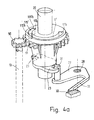
- Fig. 4a eine schaubildliche Darstellung einer sechsten Ausführungsform, bei der abweichend von der fünften Ausführungsform Nocken und Bewegungsbahn rotor- und lastseitig vertauscht sind; der Antriebsmotor ist hier nicht normal dargestellt,
- Fig. 5 eine gegenüber der Darstellung nach Fig. 4 abgewandelte Anlaufhilfe in Draufsicht mit zwei getrennten Bewegungsbahnen und Lastnocken, die auf zwei verschiedenen, unterschiedlichen Radien angeordnet sind.
- 1 is a diagrammatic representation of a first embodiment of a load shaft driven by a synchronous motor with starting aid,
- 2 shows a schematic top view of the arrangement of the start-up aid according to FIG. 1 to explain the mode of operation,
- 3 is a diagrammatic representation of a second embodiment of the starting aid using a gear with a plurality of locking lugs,
- 4 shows a fifth embodiment of the start-up aid in a top view using a transmission with only two locking lugs and increased clearance,
- 4a shows a diagrammatic representation of a sixth embodiment, in which, in deviation from the fifth embodiment, cams and movement path are interchanged on the rotor and load side; the drive motor is not shown normally here
- FIG. 5 shows a plan view of the starting aid modified compared to the representation according to FIG. 4 with two separate movement paths and load cams which are arranged on two different, different radii.
In Fig. 1 und 2 ist ein zweipoliger Einphasensynchronmotor 1 dargestellt, dessen U-förmiges Statoreisen 3 zwei Schenkel 4 mit Spulen 5 aufweist. An den Schenkeln 4 sind Polschuhe 7 ausgebildet, zwischen denen in einem Statorfeld 9 ein dauermagnetischer Rotor 11 mittels eine Welle 13 umlauffähig gelagert ist.1 and 2, a two-pole single-phase
Die Rotorwelle 13 ist mit Antriebsnocken 15 versehen, die in Kupplungsnuten 17 eines Lastteiles 19 eingreifen, von dem eine Lastwelle 20 wegführt. Die Kupplungsnuten 17 haben eine später noch definierte Länge, die es den Antriebsnocken 15 möglich macht, um einen gewissen Spielwinkel E frei drehen zu können (Fig. 2). Auf diese Weise wird ein Verdrehspiel zwischen dem Lastteil 19 und der Rotorwelle 13 eingeführt.The
An der Rotorwelle 13 sind zwei Sperrnasen 23 vorgesehen. Die Sperrnasen 23 wirken zusammen mit einem Sperrglied 27, das um eine chassisfeste Lagerung 28 drehbar ist. Das Sperrglied 27 weist einen Federarm 29 auf, der sich an einem chassisfesten Widerlager 30 abstützt. Das Sperrglied 27 trägt einen Sperrstift 31, der zum Zusammenwirken mit den Sperrnasen 23 ausgebildet ist. Der Federarm 29 drückt dazu das Sperrglied und mit ihm den Sperrstift 31 ständig in Richtung auf die Rotorwelle 13. In besonders einfacher Ausbildung bestehen das Sperrglied 27, der Sperrstift 31, der Federarm 29 und das Widerlager 30 aus einem Kunststoffspritzteil.Two locking lugs 23 are provided on the
Fig. 2 zeigt den Aufbau nach Fig. 1 in Draufsicht, wobei wieder der Einphasensynchronmotor 1 mit seinem U-förmigen Statoreisen 3, den Schenkeln 4, den Spulen 5 sowie den Statorpolen 7 zu erkennen ist, wobei im Statorfeld 9 der Rotor 11 angeordnet ist. Mit dem Rotor 11 fest verbunden ist ein Mitnehmerteil 33, welches die Antriebssnokken 15 trägt. Das Mitnehmerteil 33 ist in der Zeichnung schraffiert dargestellt. Unterhalb des Mitnehmerteiles liegen die mit dem Mitnehmerteil verbunden Sperrnasen 23.Fig. 2 shows the structure of FIG. 1 in plan view, again the single-phase
Um das Mitnehmerteil 33 herum liegt das Lastteil 19 mit den Kupplungsnuten 17. Die Kupplungsnuten 17 stellen Bewegungsbahnen dar, deren Länge begrenzt wird von positiven und negativen Lastspielwänden 35, 36, die sich an vom Lastteil 19 nach innen weisenden Lastnocken 37 ausbilden. In den Bewegungsbahnen bzw. Kupplungsnuten 17 befinden sich die Antriebsnocken 15 mit positiven und negativen Rotorspielwänden 38, 49. Das Lastteil 19 mit den Lastocken 37 ist der Übersichtlichkeit wegen doppelt schraffiert dargestellt.The
In der Zeichnung erkennt man auch das um die chassisfeste Lagerung 28 verschwenkbare Sperrglied 27 mit seinem Federarm 29 und chassifestem Widerlager 30. Die vordere Spitze des Sperrgliedes 27 trägt den Sperrstift 31.The drawing also shows the locking
Wie man aus Fig. 2 erkennt, schließen die mittlere Feldrichtung 39 des Statorfeldes 9 und die mittlere Feldrichtung 41 des zweipolig magnetisierten Rotors 11 einen Asymmetriewinkei -y ein. Dies ist der Winkel, um den sich der Rotor aufgrund des Klebemomentes beim Stillstand aus der Richtung 39 des Statorfeldes heraus verstellt. In Richtung der Linie 41 bleibt der Rotor, wenn er sich frei bewegen kann, nach dem Auslauf in einer stabilen Ruhelage stehen.As can be seen from FIG. 2, the
Der Spielwinkel E bezeichnet den Winkel, um den sich das Mitnehmerteil 33 frei gegenüber dem Lastteil 19 verschieben kann ohne Berücksichtigung des Sperrgliedes 27. Der Spielwinkel e wird bestimmt durch den freien Abstand der Lastspielwände 35/36 der Kupplungsnuten 17 abzüglich der Breite des Antriebsnockens 15 mit den Rotorspielwänden 38/49. Eingetragen ist ferner der Blockierwinkel K; er bezeichnet den Winkel zwischen Statorfeldrichtung 39 und Magnetisierungsrichtung 41, unter welchem der Rotor bei positiver Drehrichtung vor Erreichen des Parallelstandes beider Felder gesperrt wird. Der Spielwinkel e muß größer sein als der Betrag des Blockierwinkels K, damit der Rotor 11 beim Zurücklaufen des mit ihm fest verbundenen Antriebsnockens 15 aus der Anlage seiner negativen Rotorspielwand 49 an der negativen Lastspielwand 36 des Rastnockens gesperrt wird, bevor die positive Rotorspielwand 38 des Antriebsnockens die positive Lastspielwand 35 des Lastnockens erreicht, wenn diese sich in einer Stellung befindet, in welcher bei anliegenden positiven Last-und Rotorspielwänden 35, 38 die Magnetisierungsrichtung 41 des Rotors 11 parallel zur Statorfeldrichtung 39 wäre. Der Sperrpunkt sollte wenigstens um den Betrag des Asymmetriewinkels y vor Erreichen der Parallelstellung liegen.The play angle E denotes the angle by which the
Um zu vermeiden, daß beim Abschalten der Spannung der Rotor von der Last geschoben wird und somit die positiven Rotor- und Lastspielwände beim Auslaufen in Kontakt kämen, muß der Quotient aus Lastreibungsmoment und Lastträgheitsmoment größer sein als der Quotient aus Klebe-und Rotorträgheitsmoment.In order to avoid that the rotor is pushed by the load when the voltage is switched off and thus the positive rotor and load play walls come into contact when running out, the quotient of the load friction moment and the load moment of inertia must be greater than the quotient of the adhesive moment and the rotor moment of inertia.
Fig. 3 zeigt eine zweite Ausführungsform, bei der die Richtungssperre 22 an einem Getriebe zwischen der Rotorwelle 13 und der Lastwelle 20 angeordnet ist. Die schaubildliche Darstellung nach Fig. 3 zeigt wieder den Einphasensynchronmotor 1 in einer Ausführungsform entsprechend der nach Fig. 1. Auf der Rotorwelle 13 ist ein Ritzel 50 angeordnet, welches mit einem Getriebezahnrad 51 kämmt und damit ein Getriebe 47 bildet. In dem Getriebezahnrad 51 ist ein zylindrischer Freiraum vorgesehen, in den nach innen Antriebsnocken 37g hineingreifen. Damit bilden sich zwischen den Nokken 37g bogenförmige Bewegungsbahnen 17g aus, die begrenzt werden von Rotorspielwänden, nämlich einer positiven Rotorspielwand 38g und einer negativen Rotorspielwand 49g.FIG. 3 shows a second embodiment, in which the
Durch das Getriebezahnrad 51 ist die Lastwelle 20 geführt. An der Lastwelle 20 sind Nocken 15g befestigt, die seitliche Spielwände aufweisen, nämlich eine positive Lastspielwand 35g und eine negative Lastspielwand 36g. Diese Lastnocken greifen in die Bewegungsbahnen 17g ein.The
Da die Lastnocken 15g schmäler sind als die Bewegungsbahnen 17g, entsteht zwischen den Lastnocken 15g und den Bewegungsbahnen 17g ein Spielwinkel e.Since the
Das Getriebezahnrad 51 ist mit mehreren Sperrnasen 23 versehen, die an einer axialen Verlängerung 51 des Antriebszahnrades 51 angeordnet sind. Wie in der Ausführungsform nach den Fig. 1 und 2, bilden die Sperrnasen 23 zusammen mit einem Sperrstift 31 eine Richtungssperre 22. Der Sperrstift 31 ist an einem um eine chassisfeste Lagerung 28 verschwenkbaren Sperrglied 27 befestigt, das sich mit einem Federarm 29 am chassisfesten Widerlager 30 abstützt.The
Bei der Ausführungsform nach Fig. 3 ist vorgesehen, daß verdrehfest mit dem Rotor 11 über die Rotorwelle 13 das Antriebsritzel 50 antreibbar ist, das mit dem Getriebezahnrad 51 kämmt, welches zum Antriebsritzel 50 ein ganzzahliges Untersetzungsverhältnis aufweist. Der Spielwinkel e zwischen dem Getriebezahnrad 51 und der Lastwelle 20 erlaubt dem Rotor eine freie Umdrehung, die größer ist als der Blockierwinkel K, vorzugsweise größer als 90° minus dem Asymmetriewinkel y. Am Getriebezahnrad 51 ist eine dem 2-fachen des Untersetzungsverhältnisses entsprechende Zahl von Sperrnasen 23 angebracht, welche abhängig von der Stellung des Getriebezahnrades 51 und damit direkt abhängig von der Rotorstellung die positive Drehrichtung des Rotors 11 in der Drehstellung sperren, in welcher die Magnetisierungsrichtung des Rotors 11 einen negativen Blockierwinkel K mit der Statorfeldrichtung 39 einschließt, der dem Betrage nach größer ist als der Asymmetriewinkel y.In the embodiment according to FIG. 3 it is provided that the
Abweichend von der zweiten Ausführungsform nach Fig. 3 ist bei einer nicht dargestellten dritten Ausführungsform vorgesehen, daß am Gehäusezahnrad 51 eine dem Untersetzungsverhältnis entsprechende Zahl von Sperrgliedern 27 drehbar gelagert ist, welche im Zusammenwirken mit zwei am Getriebezahnrad 51 symmetrisch angeordneten Sperrnasen abhängig von der Stellung des Getriebezahnrades 51 und damit direkt abhängig von der Rotorstellung die positive Drehrichtung des Rotors in einer Drehstellung sperren, in welcher die Magnetisierungsrichtung 41 des Rotors 11 einen negativen Blockierwinkel K mit der Statorfeldrichtung 39 einschließt, der dem Betrage nach größer ist als der Asymmetriewinkel y und in den anderen Rotorstellungen die Rotordrehung nicht behindert.Deviating from the second embodiment according to FIG. 3, in a third embodiment, not shown, it is provided that a number of locking
Bei einer weiteren, nicht dargestellten vierten Ausführungsform ist, basierend auf der zweiten Ausführungsform mit dem Getriebe, vorgesehen, daß der Spielwinkel 6 zwischen den Antriebsnocken 37g und den Lastnocken 15g etwa gleich 360° geteilt durch die Anzahl der Sperrnasen 23 ist, welche abhängig von der Stellung des Getriebezahnrades 51 und damit direkt abhängig von der Rotorstellung die positive Drehrichtung des Rotors 11 in einer Drehstellung sperren, in welcher die Magnetisierungsrichtung 41 des Rotors 11 einen negativen Sperrwinkel K mit der Statorfeldrichtung 39 einschließt, der dem Betrage nach größer ist als der Asymmetriewinkel y und vorzugsweise -90° beträgt, und in den anderen Rotorstellungen die Rotordrehung nicht behindert.In a further fourth embodiment, not shown, based on the second embodiment with the transmission, it is provided that the play angle 6 between the
Je nach dem Untersetzungsverhältnis und der Anzahl der Sperrnasen bzw. Sperrglieder kann der Rotor 11 mehrere Umdrehungen in positiver Drehrichtung zurücklaufen, bevor er in der beschriebenen Stellung etwa senkrecht zum Statorfeld gesperrt wird.Depending on the reduction ratio and the number of locking lugs or locking members, the
Abweichend von der Ausführungsform nach Fig. 3, bei der eine Vielzahl von Sperrnasen 23 fest mit dem Getriebezahnrad 51 verbunden sind, ist bei einer fünften Ausführungsform nach Fig. 4 vorgesehen, daß am Getriebezahnrad 51 eine bogenförmige Bewegungsbahn 17 angeordnet ist mit Spielwänden 17a und 17b, in die ein Nocken 115 der Lastwelle 20 eingreift. Auf dem Getriebezahnrad 51 sind nur zwei symmetrisch angeordnete Sperrnasen 23 vorgesehen. Der Spielwinkel e beträgt in diesem Falle 180°, und der Blockierwinkel K bemißt sich auf-90°.3, in which a plurality of locking lugs 23 are fixedly connected to the
Fig. 4a zeigt eine sechste Ausführungsform ähnlich der nach Fig. 4, wobei nur die Anlaufhilfe ohne Antriebsmotor dargestellt ist. Dabei ist abweichend von der fünften Ausführungsform nach Fig. 4 am Getriebezahnrad 51 statt der bogenförmigen Bewegungsbahn ein Antriebsnocken 115' mit Rotorspielwänden 115'a, 115'b und auf der Lastwelle 20 anstelle des Lastnockens eine bogenförmige Bewegungsbahn 17' mit Lastspielwänden 17'a, 17'b vorgesehen.4a shows a sixth embodiment similar to that of FIG. 4, only the starting aid being shown without a drive motor. 4, a drive cam 115 'with rotor play walls 115'a, 115'b and an arc-shaped movement track 17' with load play walls 17'a on the
Fig. 5 zeigt eine abgewandelte Anlaufhilfe ähnlich der nach Fig. 4, wobei für gleiche Teile gleiche Bezugszeichen verwendet wurden. In Fig. 5 sind zwei Bewegungsbahnen 17', 17" vorgesehen, die jede mit einem Nocken 15', 15" zusammenwirken. Die Bewegungsbahnen 17', 17" sind dabei zur Erzielung eines größeren Spielwinkels auf verschiedenen Radien angeordnet und in Umfangsrichtung um 180° gegeneinander versetzt. Der Spielwinkel e beträgt wiederum 180°, der Blockierwinkel K beterägt-90°.FIG. 5 shows a modified start-up aid similar to that of FIG. 4, the same reference numerals being used for the same parts. In Fig. 5 two
Alle funktionellen Umkehrungen der Bewegungsbahnen und Nocken sind in den Rahmen der Erfindung mit einbezogen.All functional reversals of the movement paths and cams are included in the scope of the invention.
Claims (11)
Applications Claiming Priority (2)
| Application Number | Priority Date | Filing Date | Title |
|---|---|---|---|
| DE3941204 | 1989-12-14 | ||
| DE3941204A DE3941204A1 (en) | 1989-12-14 | 1989-12-14 | START-UP AID FOR A BIPOLAR SINGLE-PHASE SYNCHRONOUS MOTOR WITH PERMANENT MAGNETIC ROTOR |
Publications (2)
| Publication Number | Publication Date |
|---|---|
| EP0432852A1 true EP0432852A1 (en) | 1991-06-19 |
| EP0432852B1 EP0432852B1 (en) | 1994-05-25 |
Family
ID=6395405
Family Applications (1)
| Application Number | Title | Priority Date | Filing Date |
|---|---|---|---|
| EP90203243A Expired - Lifetime EP0432852B1 (en) | 1989-12-14 | 1990-12-10 | Starting device for a two-pole single-phase synchronous motor with permanent magnet rotor |
Country Status (4)
| Country | Link |
|---|---|
| US (1) | US5118977A (en) |
| EP (1) | EP0432852B1 (en) |
| JP (1) | JP2807350B2 (en) |
| DE (2) | DE3941204A1 (en) |
Cited By (1)
| Publication number | Priority date | Publication date | Assignee | Title |
|---|---|---|---|---|
| WO2007052210A1 (en) * | 2005-10-31 | 2007-05-10 | Arcelik Anonim Sirketi | A motor |
Families Citing this family (8)
| Publication number | Priority date | Publication date | Assignee | Title |
|---|---|---|---|---|
| US6227822B1 (en) | 1998-10-20 | 2001-05-08 | Lakewood Engineering And Manufacturing Co. | Fan with improved electric motor and mounting |
| DE10004059A1 (en) * | 2000-02-01 | 2001-11-08 | Buhler Motor Gmbh | Multi-phase motor has coil wires essentially connected directly to plug pins or conducting tracks, connecting part accepting coil wire section between each coil and plug part or circuit board |
| US6356000B1 (en) * | 2001-02-02 | 2002-03-12 | Chun-Yuan Ho | Magnetically augmented rotation system |
| US6975049B2 (en) * | 2003-10-29 | 2005-12-13 | A. O. Smith Corporation | Electrical machine and method of manufacturing the same |
| CN102824947B (en) * | 2012-07-20 | 2014-10-15 | 东莞市邦泽电子有限公司 | Paper shredder provided with permanent magnet synchronous motor |
| CN103501095B (en) * | 2013-10-07 | 2015-09-02 | 江门市地尔汉宇电器股份有限公司 | A kind of small permanent magnetic sychronous motor and draining pump using " U " font iron core |
| CN105322730B (en) * | 2014-07-28 | 2017-09-15 | 江门市地尔汉宇电器股份有限公司 | A kind of permagnetic synchronous motor and preparation method thereof |
| KR102501807B1 (en) * | 2021-07-13 | 2023-02-17 | 연세대학교 산학협력단 | Multi degree of freedom magnetic levitation system by single body actuator |
Citations (4)
| Publication number | Priority date | Publication date | Assignee | Title |
|---|---|---|---|---|
| FR2184170A5 (en) * | 1972-05-09 | 1973-12-21 | Crouzet Sa | |
| GB1413782A (en) * | 1974-05-17 | 1975-11-12 | Mallory Timers Ltd | Synchronous motor including means preventing continued rotation in a wrongway direction of the rotor |
| DE3420371A1 (en) * | 1984-01-02 | 1985-07-11 | Robert Bosch Gmbh, 7000 Stuttgart | ARRANGEMENT FOR STARTING A SYNCHRONOUS MOTOR |
| DE8703451U1 (en) * | 1987-03-07 | 1988-07-07 | Robert Bosch Gmbh, 7000 Stuttgart, De |
Family Cites Families (5)
| Publication number | Priority date | Publication date | Assignee | Title |
|---|---|---|---|---|
| US4241270A (en) * | 1977-12-27 | 1980-12-23 | Tri-Tech, Inc. | Synchronous electric motor |
| US4528533A (en) * | 1982-07-28 | 1985-07-09 | General Scanning, Inc. | Actuator with compensating flux path |
| DE3301263C2 (en) * | 1983-01-17 | 1986-07-31 | Philips Patentverwaltung Gmbh, 2000 Hamburg | Single-phase synchronous motor with a two-pole permanent magnet rotor |
| US4728832A (en) | 1986-08-07 | 1988-03-01 | Honeywell Inc. | Alternating current motor with directional rotation reliability |
| JP2604143B2 (en) * | 1987-01-14 | 1997-04-30 | 三洋電機株式会社 | Small brushless motor |
-
1989
- 1989-12-14 DE DE3941204A patent/DE3941204A1/en not_active Withdrawn
-
1990
- 1990-12-10 DE DE59005817T patent/DE59005817D1/en not_active Expired - Fee Related
- 1990-12-10 EP EP90203243A patent/EP0432852B1/en not_active Expired - Lifetime
- 1990-12-12 JP JP2409847A patent/JP2807350B2/en not_active Expired - Lifetime
- 1990-12-14 US US07/628,262 patent/US5118977A/en not_active Expired - Fee Related
Patent Citations (4)
| Publication number | Priority date | Publication date | Assignee | Title |
|---|---|---|---|---|
| FR2184170A5 (en) * | 1972-05-09 | 1973-12-21 | Crouzet Sa | |
| GB1413782A (en) * | 1974-05-17 | 1975-11-12 | Mallory Timers Ltd | Synchronous motor including means preventing continued rotation in a wrongway direction of the rotor |
| DE3420371A1 (en) * | 1984-01-02 | 1985-07-11 | Robert Bosch Gmbh, 7000 Stuttgart | ARRANGEMENT FOR STARTING A SYNCHRONOUS MOTOR |
| DE8703451U1 (en) * | 1987-03-07 | 1988-07-07 | Robert Bosch Gmbh, 7000 Stuttgart, De |
Cited By (2)
| Publication number | Priority date | Publication date | Assignee | Title |
|---|---|---|---|---|
| WO2007052210A1 (en) * | 2005-10-31 | 2007-05-10 | Arcelik Anonim Sirketi | A motor |
| CN101300724B (en) * | 2005-10-31 | 2012-07-04 | 阿塞里克股份有限公司 | A motor |
Also Published As
| Publication number | Publication date |
|---|---|
| DE59005817D1 (en) | 1994-06-30 |
| JP2807350B2 (en) | 1998-10-08 |
| JPH04105540A (en) | 1992-04-07 |
| DE3941204A1 (en) | 1991-06-20 |
| US5118977A (en) | 1992-06-02 |
| EP0432852B1 (en) | 1994-05-25 |
Similar Documents
| Publication | Publication Date | Title |
|---|---|---|
| DE60131038T2 (en) | Motor-generator | |
| DE2600840C3 (en) | Stepper motor with a permanent magnet rotor | |
| DE1538834C3 (en) | Stepper motor | |
| DE10333092A1 (en) | Rotary actuator used in e.g. parking switching apparatus of motor vehicle, has retarder whose input shaft is interlocked with rotor shaft of synchronous motor, to constitute common shaft inside main housing | |
| DE102004054397B4 (en) | Electromagnetic actuator | |
| DE112005003694T5 (en) | magnet motor | |
| EP0432852B1 (en) | Starting device for a two-pole single-phase synchronous motor with permanent magnet rotor | |
| DE2658998A1 (en) | ELECTRIC MOTOR | |
| DE1488074B2 (en) | ELECTRIC MOTOR | |
| EP0103930B1 (en) | Reversing device for a two-pole single-phase synchronous motor | |
| EP0614263A1 (en) | Single-phase reluctance motor capable of starting in a desired rotational direction | |
| DE202018103172U1 (en) | engine location | |
| DE2834579C2 (en) | engine | |
| DE3915539A1 (en) | ELECTRONICALLY COMMUTED DC MOTOR | |
| DE3049191A1 (en) | ELECTRIC STEPPER MOTOR AND COMBINATION OF MOTOR REDUCER USING IT | |
| DE2642432C2 (en) | Self-starting synchronous motor | |
| DE1802531B2 (en) | ARRANGEMENT WITH AN ELECTRIC STEPPER MOTOR | |
| DE1763855A1 (en) | Synchronous motor with a clearly definable direction of rotation | |
| EP0463590B1 (en) | Actuator for adjusting two self-holding positions | |
| DE4234388A1 (en) | Bicycle light dynamo - has iron-free armatures and is built directly into wheel hub | |
| DE1763078C3 (en) | Stepper motor | |
| DE69632662T2 (en) | Device and method for starting a single-phase reluctance motor | |
| DE2226333A1 (en) | SELF-EXCITING SYNCHRONOUS MOTOR | |
| DE1548032A1 (en) | Synchronous clock with power reserve | |
| DE19513736A1 (en) | Drive unit e.g. for vehicle |
Legal Events
| Date | Code | Title | Description |
|---|---|---|---|
| PUAI | Public reference made under article 153(3) epc to a published international application that has entered the european phase |
Free format text: ORIGINAL CODE: 0009012 |
|
| AK | Designated contracting states |
Kind code of ref document: A1 Designated state(s): DE FR GB IT |
|
| 17P | Request for examination filed |
Effective date: 19920123 |
|
| 17Q | First examination report despatched |
Effective date: 19930809 |
|
| GRAA | (expected) grant |
Free format text: ORIGINAL CODE: 0009210 |
|
| AK | Designated contracting states |
Kind code of ref document: B1 Designated state(s): DE FR GB IT |
|
| REF | Corresponds to: |
Ref document number: 59005817 Country of ref document: DE Date of ref document: 19940630 |
|
| ITF | It: translation for a ep patent filed |
Owner name: ING. C. GREGORJ S.P.A. |
|
| GBT | Gb: translation of ep patent filed (gb section 77(6)(a)/1977) |
Effective date: 19940801 |
|
| ET | Fr: translation filed | ||
| PLBE | No opposition filed within time limit |
Free format text: ORIGINAL CODE: 0009261 |
|
| STAA | Information on the status of an ep patent application or granted ep patent |
Free format text: STATUS: NO OPPOSITION FILED WITHIN TIME LIMIT |
|
| ITPR | It: changes in ownership of a european patent |
Owner name: CAMBIO RAGIONE SOCIALE;PHILIPS ELECTRONICS N.V. |
|
| 26N | No opposition filed | ||
| REG | Reference to a national code |
Ref country code: FR Ref legal event code: CD |
|
| PGFP | Annual fee paid to national office [announced via postgrant information from national office to epo] |
Ref country code: GB Payment date: 19971201 Year of fee payment: 8 |
|
| PGFP | Annual fee paid to national office [announced via postgrant information from national office to epo] |
Ref country code: FR Payment date: 19971223 Year of fee payment: 8 |
|
| PGFP | Annual fee paid to national office [announced via postgrant information from national office to epo] |
Ref country code: DE Payment date: 19980223 Year of fee payment: 8 |
|
| REG | Reference to a national code |
Ref country code: FR Ref legal event code: CD |
|
| PG25 | Lapsed in a contracting state [announced via postgrant information from national office to epo] |
Ref country code: GB Free format text: LAPSE BECAUSE OF NON-PAYMENT OF DUE FEES Effective date: 19981210 |
|
| GBPC | Gb: european patent ceased through non-payment of renewal fee |
Effective date: 19981210 |
|
| PG25 | Lapsed in a contracting state [announced via postgrant information from national office to epo] |
Ref country code: FR Free format text: LAPSE BECAUSE OF NON-PAYMENT OF DUE FEES Effective date: 19990831 |
|
| REG | Reference to a national code |
Ref country code: FR Ref legal event code: ST |
|
| PG25 | Lapsed in a contracting state [announced via postgrant information from national office to epo] |
Ref country code: DE Free format text: LAPSE BECAUSE OF NON-PAYMENT OF DUE FEES Effective date: 19991001 |
|
| PG25 | Lapsed in a contracting state [announced via postgrant information from national office to epo] |
Ref country code: IT Free format text: LAPSE BECAUSE OF NON-PAYMENT OF DUE FEES;WARNING: LAPSES OF ITALIAN PATENTS WITH EFFECTIVE DATE BEFORE 2007 MAY HAVE OCCURRED AT ANY TIME BEFORE 2007. THE CORRECT EFFECTIVE DATE MAY BE DIFFERENT FROM THE ONE RECORDED. Effective date: 20051210 |