EP0432545B1 - Molten metal stirring device - Google Patents
Molten metal stirring device Download PDFInfo
- Publication number
- EP0432545B1 EP0432545B1 EP90122406A EP90122406A EP0432545B1 EP 0432545 B1 EP0432545 B1 EP 0432545B1 EP 90122406 A EP90122406 A EP 90122406A EP 90122406 A EP90122406 A EP 90122406A EP 0432545 B1 EP0432545 B1 EP 0432545B1
- Authority
- EP
- European Patent Office
- Prior art keywords
- stirring
- tube
- stirring tube
- molten metal
- furnace
- Prior art date
- Legal status (The legal status is an assumption and is not a legal conclusion. Google has not performed a legal analysis and makes no representation as to the accuracy of the status listed.)
- Expired - Lifetime
Links
Images



Classifications
-
- C—CHEMISTRY; METALLURGY
- C22—METALLURGY; FERROUS OR NON-FERROUS ALLOYS; TREATMENT OF ALLOYS OR NON-FERROUS METALS
- C22B—PRODUCTION AND REFINING OF METALS; PRETREATMENT OF RAW MATERIALS
- C22B9/00—General processes of refining or remelting of metals; Apparatus for electroslag or arc remelting of metals
-
- F—MECHANICAL ENGINEERING; LIGHTING; HEATING; WEAPONS; BLASTING
- F27—FURNACES; KILNS; OVENS; RETORTS
- F27D—DETAILS OR ACCESSORIES OF FURNACES, KILNS, OVENS OR RETORTS, IN SO FAR AS THEY ARE OF KINDS OCCURRING IN MORE THAN ONE KIND OF FURNACE
- F27D27/00—Stirring devices for molten material
-
- C—CHEMISTRY; METALLURGY
- C22—METALLURGY; FERROUS OR NON-FERROUS ALLOYS; TREATMENT OF ALLOYS OR NON-FERROUS METALS
- C22B—PRODUCTION AND REFINING OF METALS; PRETREATMENT OF RAW MATERIALS
- C22B9/00—General processes of refining or remelting of metals; Apparatus for electroslag or arc remelting of metals
- C22B9/02—Refining by liquating, filtering, centrifuging, distilling, or supersonic wave action including acoustic waves
-
- F—MECHANICAL ENGINEERING; LIGHTING; HEATING; WEAPONS; BLASTING
- F27—FURNACES; KILNS; OVENS; RETORTS
- F27D—DETAILS OR ACCESSORIES OF FURNACES, KILNS, OVENS OR RETORTS, IN SO FAR AS THEY ARE OF KINDS OCCURRING IN MORE THAN ONE KIND OF FURNACE
- F27D27/00—Stirring devices for molten material
- F27D27/005—Pumps
- F27D27/007—Pulsating pumps
-
- Y—GENERAL TAGGING OF NEW TECHNOLOGICAL DEVELOPMENTS; GENERAL TAGGING OF CROSS-SECTIONAL TECHNOLOGIES SPANNING OVER SEVERAL SECTIONS OF THE IPC; TECHNICAL SUBJECTS COVERED BY FORMER USPC CROSS-REFERENCE ART COLLECTIONS [XRACs] AND DIGESTS
- Y02—TECHNOLOGIES OR APPLICATIONS FOR MITIGATION OR ADAPTATION AGAINST CLIMATE CHANGE
- Y02P—CLIMATE CHANGE MITIGATION TECHNOLOGIES IN THE PRODUCTION OR PROCESSING OF GOODS
- Y02P10/00—Technologies related to metal processing
- Y02P10/20—Recycling
Definitions
- This invention relates to a device to stir molten metal, especially molten aluminum. Specifically, this invention relates to a molten metal stirring device whereby a stirring tube is inserted into an insertion hole located in the wall of a melting furnace and then repeatedly sucks up and blows down the molten metal in the furnace.
- the Japanese Patent Kokai No. 52-153802 describes the structure of a stirring device in which a stirring tube penetrates through the upper part of a side wall of a melting furnace at an inclination ranging from 25 to 60 degrees. The stirring tube is fixed against the wall.
- the Japanese Patent Kokai No. 58-185730 describes a structure in which a riser tube is connected to an opening in the lower part of a side wall of a melting furnace.
- a stirring tube passes through an insertion hole in the side wall of a furnace, then the stirring tube is angled using a tilting device to allow the tip of the stirring tube dip into the molten metal.
- This improved device allows a large quantity of heat to dissipate through the insertion opening which is unavoidably enlarged to secure sufficient room for the tilting motion of the stirring tube.
- the improved device is provided with a stationary structure to mount the stirring device next to a melting furnace, every melting furnace required its own exclusive stirring device.
- GB-A-2 039 761 discloses a method and an apparatus for stirring molten metal in a furnace.
- This preknown apparatus comprises a portion of metal which is alternately withdrawn upwardly from beneath the surface of the body of molten metal and expelled into a lower region thereof through a stirrer tube which is mounted for axial reciprocation and angular swinging to thereby enable the submerged jet of expelled metal to be projected in a fan-like fashion within the limits of an angle corresponding to the dimensions of the furnace, thus providing for effective stirring of the entire body of molten metal.
- Stepwise reciprocation of the tube is effected by means of a pneumatic positioning device. The frequency of the metal-expelling cycles is varied during the operating process.
- this preknown stirring device for molten metal comprises a stirring tube insertion hole located on the sidewall of a melting furnace and penetrating through the wall at a downward inclination from the outside to the inside of the wall. Furthermore a support device installed at the outside of the furnace has an inserting mechanism to insert the stirring tube into the stirring tube insertion hole.
- This preknown stirring tube cannot be withdrawn in its entirety from the stirring tube insertion hole. Furthermore, this preknown apparatus does not contain a closure which is closed when the stirring tube is withdrawn entirely from the stirring tube insertion hole.
- Another molten metal stirring device is known from DE-A-1 816 038 and comprises a stirring tube insertion hole located on the side wall of a melting furnace and penetrating through the wall at a downward inclination from the outside to the inside of the wall. Furthermore a stirring tube stirs the molten metal in the furnace; and a support device installed in the outside of the furnace has a tilting mechanism to tilt the stirring tube to the stirring tube insertion hole.
- One object of this invention is to present a molten metal stirring device having a stirring tube which is inserted into the melting furnace only when the stirring of molten metal is required, and which does not inhibit skimming work, and which offers improved energy saving efficiency.
- a gate which can be arbitrarily opened and closed is provided at the inlet of the stirring tube insertion hole.
- a nozzle-shaped stirring tube to stir the molten metal in the melting furnace is provided, and a support structure comprising a tilting and inserting mechanism to tilt and insert the stirring tube into the stirring tube insertion hole is included in the design of the device and is installed on the outside of the melting furnace. Since the stirring device allows the stirring tube to be inserted into the furnace at an angle, the insertion opening is not necessarily enlarged, so heat dissipation from the furnace is effectively prevented.
- Another objective of this invention is to present a transportable stirring device which includes a mechanism to set a detachable stirring tube into the furnace at an angle using the above described tilting mechanism, and which gives freedom of flexible movement at the tip of the stirring tube, and which allows easy transport of the whole device.
- the transportable molten metal stirring device in which a stirring tube is mounted on a support frame connected with a tilting mechanism via a support roll, and in which the tail end of the stirring tube is supported at a cantilever support point which moves along the stirring tube axis driven by a mechanism having a positioning feature, and in which these mechanisms and operating units are mounted on a transportable base.
- the design of the equipment includes a mechanism whereby the stirring tube is placed on the support frame via a support roll under the condition that the stirring tube is supported at a cantilevered support point on the tail end part, and at the same time, since the above described support point moves along the stirring tube axis under the control of a positioning mechanism, the tip of the stirring tube which is inserted at an angle obtains an inclined angle and has freedom of axial movement. Consequently, when the tip of the stirring tube comes in contact with some of the slug deposited on the furnace wall or a deformed part of the wall surface, the flexible properties of the stirring tube prevents the generation of excess contact pressure and prevents possible failure on the tip of the stirring tube.
- the positioning mechanism guides the stirring tube to the desired site.
- all components and operation units are mounted on a transportable base, so one stirring device can handle several melting furnaces simply by moving the device to the side of a furnace which is ready to start stirring operations. This system significantly improves the operating efficiency of a melting plant.
- Fig. 1 shows a sectional side view of an example of the molten metal stirring device of this invention.
- Fig. 2 shows a sectional plan view of the stirring device of this invention illustrating the stirring state within the melting furnace.
- Fig. 3 (a) and (b) are graphs showing the uniformity of temperature of molten metal and the alloy composition of this invention.
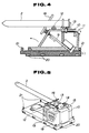
- Fig. 4 shows a sectional side view of the molten metal stirring device with a transportable structure of this invention.
- Fig. 5 is a bird's eye view of the stirring device of Fig. 4.
- Fig. 6 is a bird's eye view of the device of Fig. 4 with tilted position of the stirring tube.
- Fig. 7 is a schematic sectional view of the device of Fig. 4, the stirring tube of which is tilted and set in the melting furnace.
- the furnace wall 1 has an inclined insertion hole 3 which is opened to insert a nozzle-shaped stirring tube 2 downwardly from the outside hole opening.
- the opening of the insertion hole 3 is provided with a closure 4 which can be freely opened and closed.
- the closure 4 is attached to the opening of the insertion hole 3 by an adequate means, such as a hinge, and the opening of the insertion hole 3 is closed when the stirring tube 2 is not inserted into the furnace.
- the stirring tube 2 is mounted on the support device 5.
- the support device 5 is provided with a tilting mechanism 6 which consists of a cylinder to tilt the stirring tube 2, as illustrated in Fig. 1 with a dotted line, and other components, and also is provided with an insertion mechanism 8 which feeds the tilted stirring tube 2 toward the insertion hole 3 and dips the tip of the stirring tube 2 through the insertion hole 3 into the molten metal 7 in the melting furnace.
- the support device 5 comprises a tilting and inserting mechanism.
- the tail end of the stirring tube is connected to a vacuum unit (not shown in Fig. 1) which enables the stirring of molten metal by alternatively sucking the molten metal into the stirring tube 2 and then by blowing it into the furnace using pressure.
- the stirring device of this invention inserts the stirring tube into the furnace only when it is needed.
- the stirring device prolongs the life of the stirring tube, prevents the stirring tube from suffering damage during the charge of solid metals, and eliminates the presence of an obstructing tube in the skimming area during skimming work.
- the stirring device adopts a tilted stirring tube insertion hole on the furnace wall, obviating the need of an enlarged insertion hole and thereby preventing excess heat dissipation.
- Fig. 3 (a) shows the relationship between stirring time and temperature of aluminum molten metal when it is stirred by the stirring device of this invention. The figure indicates that 100% aluminum molten metal is brought to a uniform temperature within approximately 10 min.
- Fig. 3 (b) shows the relationship between stirring time and concentration of manganese (Mn) in the aluminum molten metal.
- the figure indicates that the alloy composition is brought into a uniform level within approximately 5 min. of stirring.
- the stirring device shown in Figs.4 and 5 is transportable and has a different structure compared with the device shown in Fig. 1.
- the transportable device has a stirring tube 2, tilting mechanism 9, support frame 10, and base 11.
- the stirring tube 2 consists of a tube with sufficient length to dip its tip into the molten metal within the melting furnace and which is supported at the support point 13 of the tail end part.
- the stirring tube 2 is supported by the support roll 12 which is fixed on the support frame 10.
- the tail end of the stirring tube 2 is connected to the suction unit 15 via the bellowstube 14.
- the stirring tube 2 is provided with a collar 16 which covers and closes the opening of the insertion hole 3 when the stirring tube 2 is inserted into the furnace at a tilted angle. Therefore, the structure shown in Figs. 4 and 5 does not require the opening of an inclined insertion hole on the furnace wall, the design of a narrow passage for the stirring tube, nor the installation of an open/close closure on the insertion hole.
- the support unit at the cantilever support point 13 is linked up to the positioning mechanism 17 which moves along the axis of the stirring tube 2.
- Fig. 4 illustrates the screw mechanism driven by a hand wheel for the positioning mechanism 17.
- the driving mechanism for the positioning feature need not be limited to the configuration shown in the figure, as other mechanisms, such as power drive unit, can be used.
- the tilting mechanism 9 consists of a free-expansion device, such as power cylinder, and functions to tilt the stirring tube 2 at a specified angle by pushing up the support frame 10 connected to the free-expansion device.
- the base 11 is designed to be transportable by having fork slots 20 attached to the bottom for a fork-lift and hooks 21 on the top for a crane.
- Fig. 7 illustrates the inserted stirring tube 2, which was preliminarily tilted as shown in Fig. 6.
- the axial movement range of the stirring tube 2 driven by the positioning mechanism 17 can be widened, or an insertion mechanism different from the positioning mechanism 17 can be added between the support frame 10 and the stirring tube 2 to perform the insertion of the stirring tube 2 into the furnace using either the positioning mechanism 17 or the newly-added insertion mechanism.
- These alternative mechanism allow the insertion of the stirring tube 2 after tilting it, so a stirring device having these mechanisms can also be applied to a furnace which has an inclined insertion hole 3.
- the structure shown in Fig. 4 includes mechanisms which can detachably insert, tilt and set a stirring tube using the positioning mechanism for the whole equipment device as a tilting function.
- the stirring equipment having the structure shown in Fig. 4 assures plant stirring operation of molten metal at a high rate supported by optimum operating conditions and efficient furnace use.
Landscapes
- Engineering & Computer Science (AREA)
- Chemical & Material Sciences (AREA)
- Mechanical Engineering (AREA)
- Organic Chemistry (AREA)
- Manufacturing & Machinery (AREA)
- Materials Engineering (AREA)
- Metallurgy (AREA)
- Acoustics & Sound (AREA)
- Physics & Mathematics (AREA)
- General Engineering & Computer Science (AREA)
- Manufacture And Refinement Of Metals (AREA)
- Waste-Gas Treatment And Other Accessory Devices For Furnaces (AREA)
- Vertical, Hearth, Or Arc Furnaces (AREA)
Description
- This invention relates to a device to stir molten metal, especially molten aluminum. Specifically, this invention relates to a molten metal stirring device whereby a stirring tube is inserted into an insertion hole located in the wall of a melting furnace and then repeatedly sucks up and blows down the molten metal in the furnace.
- Several stirring devices for molten metal have been introduced previously. The Japanese Patent Kokai No. 52-153802 describes the structure of a stirring device in which a stirring tube penetrates through the upper part of a side wall of a melting furnace at an inclination ranging from 25 to 60 degrees. The stirring tube is fixed against the wall. The Japanese Patent Kokai No. 58-185730 describes a structure in which a riser tube is connected to an opening in the lower part of a side wall of a melting furnace.
- These devices are, however, designed with fixed stirring tubes which present various troubles in its operating process. Regarding the structure of Japanese Patent Kokai No. 52-153802, solid metal charges collide with the stirring tube to damage the tip of the tube, and the high speed hot stream of the melting metal degrades the durability of the stirring tube. Furthermore, the protrusion of the stirring tube into the melting furnace hinders efficient skimming operations. For the structure of Japanese Patent Kokai No. 58-185730, the repeated melt discharge operations promotes the deposition of scum at the inlet of the opening connected to the riser tube, which then blocks the opening and results in the shut down of furnace operation.
- To resolve these problems, the inventors of this invention previously presented an improved stirring device which is described in detail in Japanese Utility Model Kokai No. 63-95099. In the improved device, a stirring tube passes through an insertion hole in the side wall of a furnace, then the stirring tube is angled using a tilting device to allow the tip of the stirring tube dip into the molten metal. This improved device, however, allows a large quantity of heat to dissipate through the insertion opening which is unavoidably enlarged to secure sufficient room for the tilting motion of the stirring tube. In addition, since the improved device is provided with a stationary structure to mount the stirring device next to a melting furnace, every melting furnace required its own exclusive stirring device. For factories operating more than one melting furnace, this pairing of furnace and stirring equipment raises the costs of plant investment and hinders efficient use of space. Another remaining problem concerned the function of stirring tube insertion adjustment to respond to the various types of furnace wall shapes or to the scum conditions inside the furnace.
- Furthermore, GB-A-2 039 761 discloses a method and an apparatus for stirring molten metal in a furnace. This preknown apparatus comprises a portion of metal which is alternately withdrawn upwardly from beneath the surface of the body of molten metal and expelled into a lower region thereof through a stirrer tube which is mounted for axial reciprocation and angular swinging to thereby enable the submerged jet of expelled metal to be projected in a fan-like fashion within the limits of an angle corresponding to the dimensions of the furnace, thus providing for effective stirring of the entire body of molten metal. Stepwise reciprocation of the tube is effected by means of a pneumatic positioning device. The frequency of the metal-expelling cycles is varied during the operating process.
- Referring to Figure 4 of this document it can be seen that this preknown stirring device for molten metal comprises a stirring tube insertion hole located on the sidewall of a melting furnace and penetrating through the wall at a downward inclination from the outside to the inside of the wall. Furthermore a support device installed at the outside of the furnace has an inserting mechanism to insert the stirring tube into the stirring tube insertion hole.
- This preknown stirring tube cannot be withdrawn in its entirety from the stirring tube insertion hole. Furthermore, this preknown apparatus does not contain a closure which is closed when the stirring tube is withdrawn entirely from the stirring tube insertion hole.
- Another molten metal stirring device is known from DE-A-1 816 038 and comprises a stirring tube insertion hole located on the side wall of a melting furnace and penetrating through the wall at a downward inclination from the outside to the inside of the wall. Furthermore a stirring tube stirs the molten metal in the furnace; and a support device installed in the outside of the furnace has a tilting mechanism to tilt the stirring tube to the stirring tube insertion hole.
- This invention is presented to solve the above described problems pertaining to conventional technologies. One object of this invention is to present a molten metal stirring device having a stirring tube which is inserted into the melting furnace only when the stirring of molten metal is required, and which does not inhibit skimming work, and which offers improved energy saving efficiency.
- These objects are achieved by the features of
claim 1. Suitable embodiments are defined by the features of the subclaims. - A gate which can be arbitrarily opened and closed is provided at the inlet of the stirring tube insertion hole. A nozzle-shaped stirring tube to stir the molten metal in the melting furnace is provided, and a support structure comprising a tilting and inserting mechanism to tilt and insert the stirring tube into the stirring tube insertion hole is included in the design of the device and is installed on the outside of the melting furnace. Since the stirring device allows the stirring tube to be inserted into the furnace at an angle, the insertion opening is not necessarily enlarged, so heat dissipation from the furnace is effectively prevented.
- Another objective of this invention is to present a transportable stirring device which includes a mechanism to set a detachable stirring tube into the furnace at an angle using the above described tilting mechanism, and which gives freedom of flexible movement at the tip of the stirring tube, and which allows easy transport of the whole device.
- This objective is achieved by the transportable molten metal stirring device in which a stirring tube is mounted on a support frame connected with a tilting mechanism via a support roll, and in which the tail end of the stirring tube is supported at a cantilever support point which moves along the stirring tube axis driven by a mechanism having a positioning feature, and in which these mechanisms and operating units are mounted on a transportable base. Since the design of the equipment includes a mechanism whereby the stirring tube is placed on the support frame via a support roll under the condition that the stirring tube is supported at a cantilevered support point on the tail end part, and at the same time, since the above described support point moves along the stirring tube axis under the control of a positioning mechanism, the tip of the stirring tube which is inserted at an angle obtains an inclined angle and has freedom of axial movement. Consequently, when the tip of the stirring tube comes in contact with some of the slug deposited on the furnace wall or a deformed part of the wall surface, the flexible properties of the stirring tube prevents the generation of excess contact pressure and prevents possible failure on the tip of the stirring tube. In addition, when the hearth depth varies or the dipping position of a stirring tube changes, the positioning mechanism guides the stirring tube to the desired site. Furthermore, all components and operation units are mounted on a transportable base, so one stirring device can handle several melting furnaces simply by moving the device to the side of a furnace which is ready to start stirring operations. This system significantly improves the operating efficiency of a melting plant.
- Fig. 1 shows a sectional side view of an example of the molten metal stirring device of this invention.
- Fig. 2 shows a sectional plan view of the stirring device of this invention illustrating the stirring state within the melting furnace.
- Fig. 3 (a) and (b) are graphs showing the uniformity of temperature of molten metal and the alloy composition of this invention.
- Fig. 4 shows a sectional side view of the molten metal stirring device with a transportable structure of this invention.
- Fig. 5 is a bird's eye view of the stirring device of Fig. 4.
- Fig. 6 is a bird's eye view of the device of Fig. 4 with tilted position of the stirring tube.
- Fig. 7 is a schematic sectional view of the device of Fig. 4, the stirring tube of which is tilted and set in the melting furnace.
- Refer to Fig. 1. The
furnace wall 1 has aninclined insertion hole 3 which is opened to insert a nozzle-shaped stirring tube 2 downwardly from the outside hole opening. The opening of theinsertion hole 3 is provided with aclosure 4 which can be freely opened and closed. Theclosure 4 is attached to the opening of theinsertion hole 3 by an adequate means, such as a hinge, and the opening of theinsertion hole 3 is closed when thestirring tube 2 is not inserted into the furnace. - The
stirring tube 2 is mounted on thesupport device 5. Thesupport device 5 is provided with atilting mechanism 6 which consists of a cylinder to tilt thestirring tube 2, as illustrated in Fig. 1 with a dotted line, and other components, and also is provided with aninsertion mechanism 8 which feeds thetilted stirring tube 2 toward theinsertion hole 3 and dips the tip of thestirring tube 2 through theinsertion hole 3 into themolten metal 7 in the melting furnace. In this way, thesupport device 5 comprises a tilting and inserting mechanism. The tail end of the stirring tube is connected to a vacuum unit (not shown in Fig. 1) which enables the stirring of molten metal by alternatively sucking the molten metal into thestirring tube 2 and then by blowing it into the furnace using pressure. - To operate the stirring device of this invention, open the
closure 4 at the opening ofinsertion hole 3, activate thetilting mechanism 6 on thesupport device 5 to tilt thestirring tube 2 as shown in Fig. 1 with the dotted line, insert thestirring tube 2 into the furnace through theinsertion hole 3 using theinsertion mechanism 8, then stop the insertion of thestirring tube 2 just before it dips into themolten metal 7. - At this point, preheat the stirring
tube 2 to the atmospheric temperature within the furnace for an adequate period, then re-activate theinsertion mechanism 8 to direct the tip (nozzle part) of the stirringtube 2 forward into themolten metal 7. Actuate the vacuum unit to perform the suction and blow-down operation of the stirringtube 2 to carry out the stirring ofmolten metal 7. After the completion of the stirring operation, raise the tip of thestirring tube 2 from the surface ofmolten metal 7 using theinsertion mechanism 8. Allow the raised stirringtube 2 to stand and let the molten metal remaining in thestirring tube 2 to completely drain out. After the draining operation, actuate theinsertion mechanism 8 to draw out the stirringtube 2 from theinsertion hole 3, and return the stirringtube 2 to the starting horizontal position using thetilting mechanism 6. Finally, close theclosure 4 at the opening ofinsertion hole 3. - As illustrated above, the stirring device of this invention inserts the stirring tube into the furnace only when it is needed. Thus, the stirring device prolongs the life of the stirring tube, prevents the stirring tube from suffering damage during the charge of solid metals, and eliminates the presence of an obstructing tube in the skimming area during skimming work. In addition, the stirring device adopts a tilted stirring tube insertion hole on the furnace wall, obviating the need of an enlarged insertion hole and thereby preventing excess heat dissipation.
- Following the above described stirring operation, when the stirring
tube 2 is set up as shown in Fig. 2, themolten metal 7 sucked into and blow down from the stirringtube 2 produces a stirring flow along the direction marked by the arrow X in Fig. 2. - Fig. 3 (a) shows the relationship between stirring time and temperature of aluminum molten metal when it is stirred by the stirring device of this invention. The figure indicates that 100% aluminum molten metal is brought to a uniform temperature within approximately 10 min. Fig. 3 (b) shows the relationship between stirring time and concentration of manganese (Mn) in the aluminum molten metal.
- The figure indicates that the alloy composition is brought into a uniform level within approximately 5 min. of stirring.
- The stirring device shown in Figs.4 and 5 is transportable and has a different structure compared with the device shown in Fig. 1. The transportable device has a stirring
tube 2,tilting mechanism 9,support frame 10, and base 11. The stirringtube 2 consists of a tube with sufficient length to dip its tip into the molten metal within the melting furnace and which is supported at thesupport point 13 of the tail end part. The stirringtube 2 is supported by thesupport roll 12 which is fixed on thesupport frame 10. The tail end of the stirringtube 2 is connected to thesuction unit 15 via thebellowstube 14. The stirringtube 2 is provided with acollar 16 which covers and closes the opening of theinsertion hole 3 when the stirringtube 2 is inserted into the furnace at a tilted angle. Therefore, the structure shown in Figs. 4 and 5 does not require the opening of an inclined insertion hole on the furnace wall, the design of a narrow passage for the stirring tube, nor the installation of an open/close closure on the insertion hole. - The support unit at the
cantilever support point 13 is linked up to thepositioning mechanism 17 which moves along the axis of the stirringtube 2. Fig. 4 illustrates the screw mechanism driven by a hand wheel for thepositioning mechanism 17. However, the driving mechanism for the positioning feature need not be limited to the configuration shown in the figure, as other mechanisms, such as power drive unit, can be used. - The
tilting mechanism 9 consists of a free-expansion device, such as power cylinder, and functions to tilt the stirringtube 2 at a specified angle by pushing up thesupport frame 10 connected to the free-expansion device. - Other than the above described stirring
tube 2,tilting mechanism 9, andsupport frame 10, all of the necessary operation units, including thesuction unit 15,control panel 18, andinstruments 19, are installed on the base 11. Also, the terminals for wiring and piping to connect with the power source and gas supply source are mounted on the base 11. - The base 11 is designed to be transportable by having
fork slots 20 attached to the bottom for a fork-lift and hooks 21 on the top for a crane. - When the stirring
tube 2 at the position shown in Fig. 4 is tilted by actuating thetilting mechanism 9, the position of the stirringtube 2 changes to that shown in Fig. 6. Fig. 7 illustrates the inserted stirringtube 2, which was preliminarily tilted as shown in Fig. 6. To insert the necessary length of the stirringtube 2 into the furnace, lift the base 11 using a fork-lift or crane and insert the stirringtube 2 into theinsertion hole 3, then put the base 11 onto the floor. When someslag 22 is deposited on the hearth, the tip of the inserted stirringtube 2 naturally moves without resistance to avoid excess contact pressure. Since thepositioning mechanism 17 allows the stirringtube 2 to move axially , it adjusts the distance between the hearth surface and the tip of the stirringtube 2 and also allows the tip to avoid contact with theslag 22. - After the completion of stirring operation using the repeated suction and blown down cycles of the stirring
tube 2, draw off the stirringtube 2 from the furnace and return the stirring device to the starting position shown in Fig. 4 by reversing the steps to the above described setting procedure. Then move the stirring equipment to the next furnace for further stirring operations. - To insert the necessary length of the stirring
tube 2 into the furnace, methods other than the transfer of base 11 may be used. For example, the axial movement range of the stirringtube 2 driven by thepositioning mechanism 17 can be widened, or an insertion mechanism different from thepositioning mechanism 17 can be added between thesupport frame 10 and the stirringtube 2 to perform the insertion of the stirringtube 2 into the furnace using either thepositioning mechanism 17 or the newly-added insertion mechanism. These alternative mechanism allow the insertion of the stirringtube 2 after tilting it, so a stirring device having these mechanisms can also be applied to a furnace which has an inclinedinsertion hole 3. - As described above, the structure shown in Fig. 4 includes mechanisms which can detachably insert, tilt and set a stirring tube using the positioning mechanism for the whole equipment device as a tilting function. With these advantageous mechanisms, the stirring equipment having the structure shown in Fig. 4 assures plant stirring operation of molten metal at a high rate supported by optimum operating conditions and efficient furnace use.
Claims (8)
- A molten metal stirring device comprising a stirring tube insertion hole (3) located on the side wall (1) of a melting furnace and penetrating through the wall (1) at a downward inclination from the outside to the inside of the wall (1), a stirring tube (2) to stir the molten metal (7) in the furnace and a support device (5), installed at the outside of the furnace and having an inserting mechanism (8) to insert the stirring tube (2) into the stirring tube insertion hole (3),
characterized in that
the inserting mechanism (8) is provided with a tilting mechanism (6,9) to tilt the stirring tube (2), that the stirring tube (2) can be withdrawn in its entirety from the stirring tube insertion hole (3), that
the stirring tube insertion hole (3) can be closed with a closure (4) when the tube (2) is withdrawn from the hole (3), that
the closure (4) is closed when the stirring tube (2) is withdrawn entirely from the stirring tube insertion hole (3), and that
the stirring tube (2) comprises a nozzle. - A molten metal stirring device of claim 1, wherein the tilting and insertion mechanism comprises a cylinder to tilt the stirring tube (2) and an insertion mechanism to move the tilted stirring tube (2) along the tube axis.
- A molten metal stirring device of claim 1 or 2, wherein the tail end of the stirring tube (2) is connected to a vacuum device which allows the stirring tube (2) to repeatedly suck up the molten metal (7) and blow it into the furnace.
- A molten metal stirring device of claim 1 to 3, wherein said tilting mechanism (9) is connected to a support frame (10) having a support roll (12) supporting the tail end of said stirring tube (2) at a cantilever support point, and having a positioning mechanism (17) to move said stirring tube (2) along the axis of said stirring tube (2), and wherein said mechanism and its operation means are mounted on a transportable base (11).
- A molten metal stirring device of claim 1 to 4, wherein a collar (16) is attached to the stirring tube (2) to close the stirring tube insertion hole (3) on the furnace wall (1).
- A molten metal stirring device of claim 1 to 5, wherein the tail end of the stirring tube (2) is connected to a suction unit (15) via a bellows tube (14).
- A molten metal stirring device of claim 1, 5 and 6, wherein the tilting mechanism (9) comprises a free-expansion device, such as a power cylinder, to push up the support frame (10) to tilt the stirring tube (2) at an arbitrary inclination.
- A molten metal stirring device of claim 1 to 7, wherein attachments (20) for a fork-lifter and/or a hook (21) for a crane is provided on the base (11).
Applications Claiming Priority (4)
| Application Number | Priority Date | Filing Date | Title |
|---|---|---|---|
| JP325481/89 | 1989-12-15 | ||
| JP1325481A JPH0752072B2 (en) | 1989-12-15 | 1989-12-15 | Molten metal agitator |
| JP4206490U JPH0645840Y2 (en) | 1990-04-19 | 1990-04-19 | Portable stirring device for molten metal |
| JP42064/90U | 1990-04-19 |
Publications (2)
| Publication Number | Publication Date |
|---|---|
| EP0432545A1 EP0432545A1 (en) | 1991-06-19 |
| EP0432545B1 true EP0432545B1 (en) | 1995-08-09 |
Family
ID=26381704
Family Applications (1)
| Application Number | Title | Priority Date | Filing Date |
|---|---|---|---|
| EP90122406A Expired - Lifetime EP0432545B1 (en) | 1989-12-15 | 1990-11-23 | Molten metal stirring device |
Country Status (4)
| Country | Link |
|---|---|
| EP (1) | EP0432545B1 (en) |
| KR (1) | KR940003506B1 (en) |
| CA (1) | CA2030855C (en) |
| DE (1) | DE69021517T2 (en) |
Families Citing this family (3)
| Publication number | Priority date | Publication date | Assignee | Title |
|---|---|---|---|---|
| CN105567997B (en) * | 2015-12-31 | 2018-06-29 | 派罗特克(广西南宁)高温材料有限公司 | Refining equipment equipment in portable furnace |
| CN108435024B (en) * | 2018-01-27 | 2025-05-06 | 南京陶特思软件科技有限公司 | A mixing device for preparing negative electrode slurry of lithium battery |
| CN115007095B (en) * | 2022-07-26 | 2024-08-09 | 中节能万润股份有限公司 | Reation kettle stirring rake dismouting auxiliary device |
Family Cites Families (4)
| Publication number | Priority date | Publication date | Assignee | Title |
|---|---|---|---|---|
| SE309050B (en) * | 1967-12-29 | 1969-03-10 | Inva Ab | |
| CA1106600A (en) * | 1977-07-25 | 1981-08-11 | Boris S. Dolzhenkov | Gas-dynamic stirring of liquid molten metals |
| DE2952978C1 (en) * | 1978-08-07 | 1982-03-11 | Boris Sergeevič Kujbyšev Dolženkov | Device for gas-dynamic mixing of liquid metal and simultaneous refining with a treatment gas in a container |
| GB2039761B (en) * | 1979-01-11 | 1982-12-15 | Dolzhenkov B | Method and apparatus for stirring molten metal |
-
1990
- 1990-11-14 KR KR1019900018376A patent/KR940003506B1/en not_active Expired - Fee Related
- 1990-11-23 EP EP90122406A patent/EP0432545B1/en not_active Expired - Lifetime
- 1990-11-23 DE DE69021517T patent/DE69021517T2/en not_active Expired - Fee Related
- 1990-11-26 CA CA002030855A patent/CA2030855C/en not_active Expired - Fee Related
Also Published As
| Publication number | Publication date |
|---|---|
| DE69021517T2 (en) | 1996-01-04 |
| EP0432545A1 (en) | 1991-06-19 |
| KR910012309A (en) | 1991-08-07 |
| DE69021517D1 (en) | 1995-09-14 |
| KR940003506B1 (en) | 1994-04-23 |
| CA2030855A1 (en) | 1991-06-16 |
| CA2030855C (en) | 1995-07-25 |
Similar Documents
| Publication | Publication Date | Title |
|---|---|---|
| US4720837A (en) | Ladle furnace | |
| CA1293110C (en) | Gunning apparatus | |
| EP0432545A1 (en) | Molten metal stirring device | |
| US6334975B1 (en) | Molten magnesium supply system | |
| US5160479A (en) | Molten metal stirring device | |
| AU643644B2 (en) | Molten metal stirring device | |
| EP1514065B1 (en) | Electromagnetic induction apparatus and method of treatment of molten materials | |
| ZA200410141B (en) | Electromagnetic induction apparatus and method of treatment of molten materials | |
| JPH0645840Y2 (en) | Portable stirring device for molten metal | |
| EP0777844B1 (en) | Apparatus and method for the supply of molten metal | |
| JPH11279617A (en) | Method for removing dust from skirt seal in converter exhaust gas treatment equipment | |
| CN219136878U (en) | Cast aluminum alloy smelting production device | |
| TW202144591A (en) | Mechanical stirring-type desulfurization system | |
| US4784207A (en) | Apparatus for vacuum melting and casting | |
| CN116944491B (en) | Ferrotitanium ingot mould upset production line | |
| JP2961302B2 (en) | Aluminum melting furnace | |
| JPS5928833B2 (en) | Method and device for stirring molten metal | |
| JPH0628800B2 (en) | Molten metal supply device | |
| JPH09206911A (en) | Closed hot water supply device and hot water supply method | |
| JPH086240Y2 (en) | Portable stirring device for molten metal | |
| KR102882909B1 (en) | Apparatus for removing residue of discharge of plasma melting furnace | |
| JP2006097078A (en) | How to remove slag | |
| GB2039761A (en) | Method and apparatus for stirring molten metal | |
| JPH0438240Y2 (en) | ||
| JPH0649553A (en) | Melting device |
Legal Events
| Date | Code | Title | Description |
|---|---|---|---|
| PUAI | Public reference made under article 153(3) epc to a published international application that has entered the european phase |
Free format text: ORIGINAL CODE: 0009012 |
|
| AK | Designated contracting states |
Kind code of ref document: A1 Designated state(s): DE FR GB IT SE |
|
| RAP1 | Party data changed (applicant data changed or rights of an application transferred) |
Owner name: SUMITOMO LIGHT METAL INDUSTRIES, LTD. |
|
| 17P | Request for examination filed |
Effective date: 19910820 |
|
| 17Q | First examination report despatched |
Effective date: 19930505 |
|
| GRAA | (expected) grant |
Free format text: ORIGINAL CODE: 0009210 |
|
| ITF | It: translation for a ep patent filed | ||
| AK | Designated contracting states |
Kind code of ref document: B1 Designated state(s): DE FR GB IT SE |
|
| REF | Corresponds to: |
Ref document number: 69021517 Country of ref document: DE Date of ref document: 19950914 |
|
| ET | Fr: translation filed | ||
| PLBE | No opposition filed within time limit |
Free format text: ORIGINAL CODE: 0009261 |
|
| STAA | Information on the status of an ep patent application or granted ep patent |
Free format text: STATUS: NO OPPOSITION FILED WITHIN TIME LIMIT |
|
| 26N | No opposition filed | ||
| PGFP | Annual fee paid to national office [announced via postgrant information from national office to epo] |
Ref country code: GB Payment date: 19971103 Year of fee payment: 8 |
|
| PGFP | Annual fee paid to national office [announced via postgrant information from national office to epo] |
Ref country code: FR Payment date: 19971117 Year of fee payment: 8 |
|
| PGFP | Annual fee paid to national office [announced via postgrant information from national office to epo] |
Ref country code: SE Payment date: 19971121 Year of fee payment: 8 |
|
| PGFP | Annual fee paid to national office [announced via postgrant information from national office to epo] |
Ref country code: DE Payment date: 19980121 Year of fee payment: 8 |
|
| PG25 | Lapsed in a contracting state [announced via postgrant information from national office to epo] |
Ref country code: GB Free format text: LAPSE BECAUSE OF NON-PAYMENT OF DUE FEES Effective date: 19981123 |
|
| PG25 | Lapsed in a contracting state [announced via postgrant information from national office to epo] |
Ref country code: SE Free format text: LAPSE BECAUSE OF NON-PAYMENT OF DUE FEES Effective date: 19981124 |
|
| GBPC | Gb: european patent ceased through non-payment of renewal fee |
Effective date: 19981123 |
|
| PG25 | Lapsed in a contracting state [announced via postgrant information from national office to epo] |
Ref country code: FR Free format text: LAPSE BECAUSE OF NON-PAYMENT OF DUE FEES Effective date: 19990730 |
|
| EUG | Se: european patent has lapsed |
Ref document number: 90122406.3 |
|
| REG | Reference to a national code |
Ref country code: FR Ref legal event code: ST |
|
| PG25 | Lapsed in a contracting state [announced via postgrant information from national office to epo] |
Ref country code: DE Free format text: LAPSE BECAUSE OF NON-PAYMENT OF DUE FEES Effective date: 19990901 |
|
| PG25 | Lapsed in a contracting state [announced via postgrant information from national office to epo] |
Ref country code: IT Free format text: LAPSE BECAUSE OF NON-PAYMENT OF DUE FEES Effective date: 20051123 |