EP0432002B1 - Vorrichtung zur automatischen und fortlaufenden Ermittlung von Parametern, die das Zusammenwirken von Boden, Pflanzen und Klima kennzeichnen - Google Patents
Vorrichtung zur automatischen und fortlaufenden Ermittlung von Parametern, die das Zusammenwirken von Boden, Pflanzen und Klima kennzeichnen Download PDFInfo
- Publication number
- EP0432002B1 EP0432002B1 EP90403269A EP90403269A EP0432002B1 EP 0432002 B1 EP0432002 B1 EP 0432002B1 EP 90403269 A EP90403269 A EP 90403269A EP 90403269 A EP90403269 A EP 90403269A EP 0432002 B1 EP0432002 B1 EP 0432002B1
- Authority
- EP
- European Patent Office
- Prior art keywords
- sensors
- mast
- sensor
- soil
- air
- Prior art date
- Legal status (The legal status is an assumption and is not a legal conclusion. Google has not performed a legal analysis and makes no representation as to the accuracy of the status listed.)
- Expired - Lifetime
Links
- 238000005259 measurement Methods 0.000 title claims description 29
- 239000002689 soil Substances 0.000 title claims description 11
- 230000003993 interaction Effects 0.000 title 1
- BASFCYQUMIYNBI-UHFFFAOYSA-N platinum Chemical compound [Pt] BASFCYQUMIYNBI-UHFFFAOYSA-N 0.000 claims description 16
- 230000005855 radiation Effects 0.000 claims description 9
- 229910052697 platinum Inorganic materials 0.000 claims description 8
- 230000001681 protective effect Effects 0.000 claims description 8
- 239000000523 sample Substances 0.000 claims description 8
- 238000012545 processing Methods 0.000 claims description 7
- 238000006243 chemical reaction Methods 0.000 claims description 3
- 230000000694 effects Effects 0.000 claims description 3
- 230000008020 evaporation Effects 0.000 claims description 3
- 238000001704 evaporation Methods 0.000 claims description 3
- 238000010438 heat treatment Methods 0.000 claims description 2
- 230000000630 rising effect Effects 0.000 claims description 2
- 238000007599 discharging Methods 0.000 claims 1
- 239000003570 air Substances 0.000 description 24
- XLYOFNOQVPJJNP-UHFFFAOYSA-N water Substances O XLYOFNOQVPJJNP-UHFFFAOYSA-N 0.000 description 8
- 238000009434 installation Methods 0.000 description 6
- 230000004907 flux Effects 0.000 description 4
- 239000012080 ambient air Substances 0.000 description 3
- 230000008901 benefit Effects 0.000 description 3
- 238000004519 manufacturing process Methods 0.000 description 3
- 238000005070 sampling Methods 0.000 description 3
- 230000012010 growth Effects 0.000 description 2
- 238000003306 harvesting Methods 0.000 description 2
- 238000012423 maintenance Methods 0.000 description 2
- 238000000034 method Methods 0.000 description 2
- 230000003071 parasitic effect Effects 0.000 description 2
- 230000010287 polarization Effects 0.000 description 2
- 238000001556 precipitation Methods 0.000 description 2
- 230000009897 systematic effect Effects 0.000 description 2
- 206010001488 Aggression Diseases 0.000 description 1
- 241001416181 Axis axis Species 0.000 description 1
- 208000005156 Dehydration Diseases 0.000 description 1
- 206010061217 Infestation Diseases 0.000 description 1
- 230000006978 adaptation Effects 0.000 description 1
- 230000016571 aggressive behavior Effects 0.000 description 1
- 230000032683 aging Effects 0.000 description 1
- 238000013459 approach Methods 0.000 description 1
- 230000000712 assembly Effects 0.000 description 1
- 238000000429 assembly Methods 0.000 description 1
- 230000005540 biological transmission Effects 0.000 description 1
- 230000015556 catabolic process Effects 0.000 description 1
- 230000008859 change Effects 0.000 description 1
- 238000004891 communication Methods 0.000 description 1
- 230000000295 complement effect Effects 0.000 description 1
- 239000013078 crystal Substances 0.000 description 1
- 238000006731 degradation reaction Methods 0.000 description 1
- 238000013461 design Methods 0.000 description 1
- 230000006866 deterioration Effects 0.000 description 1
- 238000010586 diagram Methods 0.000 description 1
- 201000010099 disease Diseases 0.000 description 1
- 208000037265 diseases, disorders, signs and symptoms Diseases 0.000 description 1
- 239000006185 dispersion Substances 0.000 description 1
- 238000011156 evaluation Methods 0.000 description 1
- 239000003337 fertilizer Substances 0.000 description 1
- 230000002068 genetic effect Effects 0.000 description 1
- 230000010354 integration Effects 0.000 description 1
- 239000000463 material Substances 0.000 description 1
- 230000007246 mechanism Effects 0.000 description 1
- 238000012986 modification Methods 0.000 description 1
- 230000004048 modification Effects 0.000 description 1
- 238000012544 monitoring process Methods 0.000 description 1
- 210000000056 organ Anatomy 0.000 description 1
- 230000008635 plant growth Effects 0.000 description 1
- 230000008569 process Effects 0.000 description 1
- 230000000750 progressive effect Effects 0.000 description 1
- 230000003252 repetitive effect Effects 0.000 description 1
- 230000002441 reversible effect Effects 0.000 description 1
- 238000011144 upstream manufacturing Methods 0.000 description 1
- 238000009423 ventilation Methods 0.000 description 1
Images

Classifications
-
- A—HUMAN NECESSITIES
- A01—AGRICULTURE; FORESTRY; ANIMAL HUSBANDRY; HUNTING; TRAPPING; FISHING
- A01G—HORTICULTURE; CULTIVATION OF VEGETABLES, FLOWERS, RICE, FRUIT, VINES, HOPS OR SEAWEED; FORESTRY; WATERING
- A01G7/00—Botany in general
-
- G—PHYSICS
- G01—MEASURING; TESTING
- G01W—METEOROLOGY
- G01W1/00—Meteorology
- G01W1/02—Instruments for indicating weather conditions by measuring two or more variables, e.g. humidity, pressure, temperature, cloud cover or wind speed
- G01W1/04—Instruments for indicating weather conditions by measuring two or more variables, e.g. humidity, pressure, temperature, cloud cover or wind speed giving only separate indications of the variables measured
-
- Y—GENERAL TAGGING OF NEW TECHNOLOGICAL DEVELOPMENTS; GENERAL TAGGING OF CROSS-SECTIONAL TECHNOLOGIES SPANNING OVER SEVERAL SECTIONS OF THE IPC; TECHNICAL SUBJECTS COVERED BY FORMER USPC CROSS-REFERENCE ART COLLECTIONS [XRACs] AND DIGESTS
- Y02—TECHNOLOGIES OR APPLICATIONS FOR MITIGATION OR ADAPTATION AGAINST CLIMATE CHANGE
- Y02A—TECHNOLOGIES FOR ADAPTATION TO CLIMATE CHANGE
- Y02A90/00—Technologies having an indirect contribution to adaptation to climate change
- Y02A90/10—Information and communication technologies [ICT] supporting adaptation to climate change, e.g. for weather forecasting or climate simulation
Definitions
- the present invention relates to a device allowing automatic and continuous data acquisition, characterizing in particular a set of soil, plants, climate, and suitable for representing the reactions of a crop of plants within its environment.
- the object of the invention is in particular to continuously provide a precise evaluation of the energy balance of this culture and of the actual evapotranspiration of plants, that is to say the amount of water lost by them in the natural conditions in which they are found.
- the measurement of sensible and latent heat fluxes entering into the equation of the energy balance of a culture at the same time as the net radiation and the density of heat fluxes by conduction to the Soil surface, as well as the determination of the actual evapotranspiration, are so far obtained from the values of the dry and humid temperature gradients of the air above the plant cover, between two levels of readings, and on the other side of an intermediate reference axis, these readings being carried out by means of apparatuses known under the name of psychrometers.
- These measurements require the use of a mechanical assembly which pivots or moves relative to the reference axis, so as to reverse the relative positions of two psychrometers, to eliminate systematic errors in the acquisition of the measured results.
- the calculation can then, from the data thus obtained, determine the temperature difference in the air and the concentration of water vapor above the culture as well as the heat fluxes sought.
- the measurement of actual evapotranspiration by means of two differential mounted psychrometers is i.e. by means of devices using, in combination with sensors for measuring temperature and other parameters (thermocouples, platinum probes, fluxmeters, anemometers ...), permanent humidification organs of a wick within which the wet temperature of the ambient environment is noted, requires relatively high investments and above all requires delicate manipulations which make the use of these devices not conducive to use by individuals and to mass production, the effective implementation of these psychrometers being essentially reserved for specialized and highly equipped laboratories.
- the present invention relates to a device which aims at acquiring climatic data suitable for direct calculation of the energy balance and of the actual evapotranspiration produced, itself assessed by a measurement of the air temperature and the relative humidity of the medium, or the concentration of water vapor in the air, which is easy to operate and does not require complex implementation, both with regard to the means used and in processing the results they provide.
- the invention relates more particularly to a device which is robust and reliable, capable of providing reliable and repetitive measurements in places which may be distant or difficult to access, requires only minimal maintenance, and is simple to implement, in particular by a farmer without requiring special precautions and above all gives information immediately exploitable by an appropriate processing system.
- this device for the automatic and continuous acquisition of data characterizing in particular a set of soil, plants, climate, and suitable for determining the reactions of a culture of plants forming a plant cover, within its environment, so as to provide the energy balance of the culture, the corresponding actual evapotranspiration and the stomatic resistance of the plant cover, comprising a mast or similar support, generally vertical, rising above the cover of the culture for the support of an assembly of measurement and possibly of various complementary sensors, is characterized in that this measurement assembly is constituted by a tube element, extending horizontally, arranged parallel to the culture and containing a temperature sensor, in particular of the thermocouple type or platinum probe , and a relative humidity sensor ensuring the measurement of a current of air drawn in by a fan or a pump, mounted at one open end of the tube element, the other end being secured and connected to two coaxial conduits , opposite and identical, preferably extending vertically on either side of the axis of the tube element and opening at two reference levels symmetrical with respect
- each of the coaxial conduits comprises, at its end opposite to the horizontal tube element, an elbow whose terminal end is parallel to the element and comprises a filter for the air drawn into the corresponding conduit.
- the coaxial conduits and the tube element are jacketed by a common protective tubular casing capable of limiting the parasitic heating of the air sucked in before it reaches the temperature and temperature sensors. hygrometry.
- the envelope of protection can be externally white in color, to reduce the effect of solar radiation.
- the temperature sensor consists of an element of the platinum probe type, mounted in a measurement bridge, supplied with a given reference voltage.
- the hygrometry sensor is for its part a resistive sensor, associated with an alternating source at fixed frequency and of constant amplitude, supplying the sensor by means of a voltage divider, the alternating polarization of the sensor making it possible to avoid a change in its properties over time. Any other relative humidity sensor (capacitive sensor for example) can naturally be used under the same conditions.
- the two sensors are combined with an electronic processing circuit, delivering electrical signals representative of the measurements carried out, this circuit preferably being contained in a waterproof protective box, carried by the mast or separated from it.
- the box is arranged inside an external chimney, provided with a deflector cover at its upper end, sufficient space being provided between the box and the internal wall of the chimney to allow, by natural convection, a air circulation around the cabinet.
- the mast or support of the measuring assembly is kept vertical by means of retaining slings, distributed around its axis and respectively fixed at a given point of the mast and to stakes immobilization on the ground.
- the mast is formed of modular elements, with successive interlockings, making it possible to increase its height as the crop grows.
- the device considered may be fitted with other sensors, providing additional measurements in the environment, in particular a solar radiation sensor and an anemometer and a wind vane, respectively giving the force and the direction of the wind.
- the device may include sensors buried in the ground or arranged in the immediate vicinity of its surface, in particular for measuring the heat flow by conduction therein.
- specific measuring devices can be provided for recording the duration of sunshine, the amount of precipitation and the internal water pressure of the soil, the air and soil temperature on several levels.
- the measurement installation considered, designated as a whole by the reference 1 consists in particular of a mast or similar support 2, the lower end of which is sunk into the ground or placed on a support plate 3, so as to extend vertically above the cover of a crop of plants 4, schematically represented in the drawing.
- the mast 2 preferably has a structure formed of successive elements such as 2a, 2b, 2c, with sockets 5. Slings 6 are moreover regularly distributed around the mast 2, being fixed on the one hand to a piece of fastener 7 provided in the vicinity of the upper part of the mast and on the other hand to ground stakes 8.
- the installation 1 is in particular provided for ensuring an appropriate measurement of the temperature of the ambient air above the cover of the culture 4 and of the humidity, in particular in two reference levels, under conditions allowing, by applying suitable formulas, a calculation of the energy balance of the crop and the corresponding actual evaporation.
- the mast 2 supports a specific device 9, the details of which will be explained below in relation to FIG. 2, the information provided by the sensors with which this device is provided being routed to an electronic processing circuit, mounted in a protective box 10, also carried by the mast but which could possibly be separated from the latter.
- the latter also supports other measurement means, such as for example, at the end of a yard 11, a wind vane 12 and an anemometer 13, respectively giving the direction and the force of the wind.
- a device 14 for measuring the duration of sunshine On the mast can also be mounted a device 14 for measuring the duration of sunshine, a sensor 15 of the intensity of solar radiation and of radiation reflected by the ground and a rain gauge 16 for measuring the height of the precipitation received by Culture.
- a sensor 15 of the intensity of solar radiation and of radiation reflected by the ground In the ground 3, are still buried other sensors such as 17a and 17b, suitable, to give at different depths, an estimate of the heat flux by conduction by the ground, as well as a tensiometric sensor 18 and ground temperature sensors at different levels.
- a sensor 19 can also give the temperature of the air under cover of the culture 4.
- All the data thus collected are stored and then transmitted, by appropriate channels (wires, radio, telephone, satellite) to a computer 21, adapted to process these data using expert software and, where appropriate, localized models, including the design and operation, if they do not directly relate to the invention, nevertheless constitute an extension thereof, allowing optimal use of the information collected with a view to better management of the possibilities of cultivation, and to the appropriate choice of appropriate solutions to ensure its protection against external aggressions and improve its productivity.
- Figure 2 illustrates on a larger scale the device 9 for measuring the air temperature and the ambient humidity level, above the cover of the culture. It comprises in particular a central tube element 22, open at its ends and in the vicinity of one of which is mounted a ventilation or pump mechanism 23, suitable for sucking air through the tube element, by rejecting it then outwards in the direction of the arrow 24.
- a ventilation or pump mechanism 23 suitable for sucking air through the tube element, by rejecting it then outwards in the direction of the arrow 24.
- sensors 25 and 26 are arranged in the element 22, upstream of the fan or of the pump 23 with respect to the air flow direction, one of which is a temperature sensor, in particular consisting of a platinum probe, while the other is a resistive humidity sensor, that is to say an assembly whose electrical resistance is a function of the degree d humidity present in the intake air.
- the tube element 22 opens at its opposite end in a part common to the center of two identical and coaxial conduits, respectively 27 and 28, thus forming with element 22 a T whose ends of the transverse branch include bends 29 and 30, extending parallel to the element 22.
- the conduits 27 and 28 are mounted valves or other similar members, respectively 27a and 28a, allowing by appropriate control, to open or close alternately each conduit of such so that the air sucked in by the fan or pump 23 comes from the region situated above the cover of the crop, in line with one or the other of the elbows 29 or 30.
- Element 22 is supported by the mast ( Figure 1) so as to extend horizontally, the conduits 27 and 28 being vertical and parallel to the mast 2.
- the elbows 29 and 30 are open in the ambient air above the covered with culture 4 and are preferably provided with filters such as 31.
- the central tube element 22 and the opposite conduits 27 and 28 are advantageously arranged inside a common envelope 32 or another tube, a layer of free air separating the envelope tube from the supply tube, intended to ensure adequate protection of the device, in particular with respect to solar radiation, the envelope 32 being preferably painted white or coated with a material with appropriate reflecting power. As illustrated elsewhere in FIG.
- the box 10 containing the electronic circuit for processing the data supplied by the sensors 25 and 26 is itself placed in the center of an external protective chimney 33, open at its ends and associated with its upper part has a deflector cover 34 so that the outside air can freely circulate between the internal wall of the chimney and the box 10 by natural convection, ensuring the evacuation of calories and also participating in the protection of the cabinet against solar radiation.
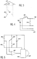
- FIG. 4 the resistance of the sensor 26 is shown mounted in series with an alternating voltage source 36, at fixed frequency and at constant amplitude, the input voltage being measured at 37, the output voltage being in turn measured at 38 across a fixed resistor 39.
- the frequency of the source is close to 1 Khz, the alternating polarization of the sensor thus produced making it possible to avoid a crystal modification of the latter and consequently a progressive deterioration, risking to distort the measurements.
- the diagram in Figure 5 illustrates for its part the mounting of the temperature sensor 25, the 3-wire platinum probe which it comprises being disposed in a measurement bridge comprising three fixed resistors, respectively 40, 41 and 42.
- the bridge is supplied by a DC voltage source 43, the output voltage measured at 44 between the terminals of the bridge being routed to an amplifier 45 and a digital analog converter 46, itself supplied by the source 43 as reference voltage.
- the output 47 of the converter is routed to the computer 21 ( Figure 1).
- This arrangement allows in particular that a variation on the reference voltage, due to the aging of the source components or to thermal drifts, is transmitted both to the measurement bridge and to the converter, the assembly thus being made practically insensitive to these variations.
- the wet temperature precisely corresponding to the measured humidity
- the differential measurement of temperature and of the relative humidity between the two is determined by calculation, in particular using appropriate software. Levels performed with the advantage of eliminating any systematic error made by the sensors. Knowing the value of the resistance of the hygrometry sensor and the temperature of the ambient air, the value of the relative humidity is then determined by interpolation and by successive approximations, the wet temperature corresponding to this.
- the integration into the database of the expert software software of the information thus acquired, or even of any other, also makes it possible to constitute a system of decision support for the user, immediately available and suitable for being exploited by procedures. simple, easily accessible.
- connection between the computer and the data acquisition device could be different and not use a connection cable but a remote transmission system by telephone line or any other means of communication, like modem, switched network, radio frequency, infrared ....
- the temperature sensor and the hygrometry sensor in the horizontal tube element 22 to which the opposite opposite and identical vertical coaxial conduits 27 and 28 are connected, with a valve or similar member housed in each of these ducts to allow alternative air sampling at two separate levels
- the single fan 23, disposed in the middle tube element could be replaced by two separate fans, mounted respectively in each of the vertical ducts, so as to suck the air taken up by these ducts alternately in one and in the other to return it to the sensors arranged in the middle tube element.
- the sensors 25 and 26 can be calibrated by being located at the same level, for a given period of time, preferably determined by the software of the computer 21, which can extend from a few minutes to a few hours, the same software automatically taking into account the data relating to this sampling, collected by the sensors.
- the device 9 is brought back to the vertical position, the calibration coefficients being calculated and saved by the computer before being taken into account to systematically correct the measurement errors, prior to the establishment of the balance sheet d energy of culture and the corresponding value of actual evapotranspiration.
Landscapes
- Life Sciences & Earth Sciences (AREA)
- Environmental & Geological Engineering (AREA)
- Biodiversity & Conservation Biology (AREA)
- Ecology (AREA)
- Environmental Sciences (AREA)
- Engineering & Computer Science (AREA)
- Atmospheric Sciences (AREA)
- Botany (AREA)
- Forests & Forestry (AREA)
- Testing Or Calibration Of Command Recording Devices (AREA)
- Cultivation Receptacles Or Flower-Pots, Or Pots For Seedlings (AREA)
Claims (14)
- Vorrichtung zur automatischen und kontinuierlichen Ermittlung von Parametern, die besonders das Zusammenwirken von Boden, Pflanzen und Klima kennzeichnen und geeignet sind zur Bestimmung der Reaktionen einer Pflanzenkultur, die im Bereich ihrer Umgebung eine den Boden mehr oder weniger bedeckende Pflanzung bildet, um auf diese Weise die Energiebilanz der Kultur, die entsprechende reale Verdunstungstranspiration (Evapotranspiration) und den Porenwiderstand der Pflanzung zu liefern, wobei diese Vorrichtung einen im allgemeinen vertikalen Mast oder entsprechenden Träger (2) aufweist, der sich über die Pflanzung (4) erhebt, um eine Meßanordnung (9) und gegebenenfalls verschiedene zusätzliche Meßfühler zu tragen, wobei diese Vorrichtung dadurch gekennzeichnet ist, daß diese Meßanordnung aus einem Rohrelement (22) besteht, das sich horizontal erstreckt, parallel zur Kultur angeordnet ist, und einen Temperaturfühler (25), besonders von der Art Thermoelement oder Platindrahtsonde, und einen Meßfühler für die relative Feuchtigkeit (26) enthält und zur Messung eines Luftstromes dient, der von einem Ventilator oder einer Pumpe (23) angesaugt wird, die an einem offenen Ende des Rohrelements montiert sind, wobei das andere Ende feststehend an zwei entgegengesetzte und identische koaxiale Leitungen (27, 28) angeschlossen ist, die sich vorzugsweise vertikal beiderseits der Achse des Rohrelements erstrecken und auf zwei verschiedenen, bezüglich dieser Achse symmetrischen Bezugsniveaus oberhalb der Pflanzung (4) münden, wobei jede Leitung mindestens ein Ventil (27a, 28a) aufweist, das abwechselnd die eine oder andere Leitung öffnet oder schließt, so daß der Ventilator oder die Pumpe die Luft ansaugen, die in diesen Leitungen nach der Herkunft von den zwei Niveaus getrennt aufgefangen wird.
- Vorrichtung nach Anspruch 1, dadurch gekennzeichnet, daß jede der Leitungen (27, 28) an ihrem dem horizontalen Rohrelement (22) entgegengesetzten Ende ein Knie (29, 30) aufweist, dessen Ende zum Rohrelement parallel ist und ein Filter (31) für die in die entsprechende Leitung angesaugte Luft aufweist.
- Vorrichtung nach Anspruch 1 oder 2, dadurch gekennzeichnet, daß die Leitung (27, 28) und das Rohrelement (22) von einer gemeinsamen rohrförmigen Schutzhülle (32) umhüllt sind, welche die störende Erwärmung der angesaugten Luft, bevor diese die Temperatur- und Feuchtigkeitsmeßfühler (25, 26) erreicht, begrenzt.
- Vorrichtung nach Anspruch 3, dadurch gekennzeichnet, daß die Schutzhülle (32) außen weiß ist, um die Wirkung der Sonnenstrahlen zu verringern.
- Vorrichtung nach einem der Ansprüche 1 bis 4, dadurch gekennzeichnet, daß der Temperaturfühler (25) von einem Element von der Art Platindrahtsonde gebildet wird, das in einer Meßbrücke montiert ist, die mit einer gegebenen Bezugsspannung gespeist wird.
- Vorrichtung nach einem der Ansprüche 1 bis 4, dadurch gekennzeichnet, daß der Hygrometer-Meßfühler (26) ein Widerstandsfühler ist, der mit einer Wechselstromquelle (36) mit fester Freqeunz und konstanter Amplitude zusammenwirkt, welche den Meßfühler über eine Spannungsteiler (39) speist.
- Vorrichtung nach einem der Ansprüche 1 bis 6, dadurch gekennzeichnet, daß die zwei Meßfühler (25, 26) mit einem elektronischen Datenbehandlungskreis oder Rechner (21) verbunden sind, der für die durchgeführten Messungen repräsentative elektrische Signale liefert, wobei dieser Schaltkreis vorzugsweise in einem dichten Schutzkasten (10) enthalten ist, der vom Mast (2) getragen oder von diesem getrennt ist.
- Vorrichtung nach Anspruch 7, dadurch gekennzeichnet, daß der Schutzkasten (10) im Inneren eines Außenkamins (33) angeordnet ist, der an seinem oberen Ende eine Abdeckhaube (34) aufweist, wobei zwischen dem Kasten und der Innenwand des Kamins ein genügender Platz vorgesehen ist, um rings um den Kasten einen Luftstrom durch natürliche Konvektion zu ermöglichen.
- Vorrichtung nach einem der Ansprüche 1 bis 8, dadurch gekennzeichnet, daß der Mast oder Träger (2) der Meßanordnung (9) mittels Spannseilen (6) vertikal gehalten ist, die rings um seine Achse verteilt und jeweils an einem gegebenen Punkt (7) des Mastes und an in den Boden geschlagenen Pflöcken (Heringen) (8) befestigt sind.
- Vorrichtung nach Anspruch 9, dadurch gekennzeichnet, daß der Mast (2) aus aufeinanderfolgend ineinandergesteckten modularen Elementen besteht, welche eine Vergrößerung seiner Höhe nach Maßgabe des Wachstums der Pflanzung (4) ermöglichen.
- Vorrichtung nach einem der Ansprüche 1 bis 9, dadurch gekennzeichnet, daß sie noch andere Meßfühler aufweist, welche komplementäre Messungen in der Umgebung liefern, insbesondere ein Meßgerät für die Sonneneinstrahlung (15), ein Anemometer (13) und eine Windfahne (12), welche jeweils die Stärke und Richtung des Windes liefern.
- Vorrichtung nach Anspruch 11, dadurch gekennzeichnet, daß sie auch in den Boden versenkte oder in unmittelbarer Nähe der Oberfläche angeordnete Meßfühler (17) aufweist, insbesondere zur Messung des Wärmeflusses durch Leitung in diesem.
- Vorrichtung nach Anspruch 11, dadurch gekennzeichnet, daß sie als Ergänzung der Geräte zur speziellen Messung der Sonneneinstrahlungsdauer (14), der Niederschlagshöhe (16) und der inneren Wasserspannung des Bodens Temperaturmeßfühler im Boden aufweist.
- Vorrichtung nach einem der Ansprüche 1 bis 13, dadurch gekennzeichnet, daß die Meßanordnung (9) bezüglich des Mastes (2) um 90° schwenkbar ist, um die Leitungen (27, 28) in einer horizontalen Ebene anzuordnen und so eine Eichung der Meßfühler (25, 26) vor den mit diesen Meßfühlern durchgeführten Messungen zu ermöglichen.
Applications Claiming Priority (2)
| Application Number | Priority Date | Filing Date | Title |
|---|---|---|---|
| FR8915262 | 1989-11-21 | ||
| FR8915262A FR2654853B1 (fr) | 1989-11-21 | 1989-11-21 | Procede pour l'acquisition automatique et continue de donnees caracterisant ensemble sol, plante, climat, et dispositif pour la mise en óoeuvre de ce procede. |
Publications (2)
| Publication Number | Publication Date |
|---|---|
| EP0432002A1 EP0432002A1 (de) | 1991-06-12 |
| EP0432002B1 true EP0432002B1 (de) | 1994-01-05 |
Family
ID=9387603
Family Applications (1)
| Application Number | Title | Priority Date | Filing Date |
|---|---|---|---|
| EP90403269A Expired - Lifetime EP0432002B1 (de) | 1989-11-21 | 1990-11-20 | Vorrichtung zur automatischen und fortlaufenden Ermittlung von Parametern, die das Zusammenwirken von Boden, Pflanzen und Klima kennzeichnen |
Country Status (3)
| Country | Link |
|---|---|
| EP (1) | EP0432002B1 (de) |
| ES (1) | ES2048469T3 (de) |
| FR (1) | FR2654853B1 (de) |
Families Citing this family (7)
| Publication number | Priority date | Publication date | Assignee | Title |
|---|---|---|---|---|
| FR2679413B1 (fr) * | 1991-07-24 | 1993-10-15 | Gilbert Picq | Procede de gestion de l'irrigation de cultures et dispositif pour sa mise en óoeuvre. |
| GB2288246A (en) * | 1994-04-07 | 1995-10-11 | Helix Ltd | Meteorological apparatus |
| ES2112194B1 (es) * | 1995-12-04 | 1998-11-16 | Munoz Carpena Rafael | Estacion micrometeorologica automatica. |
| FR2750771B1 (fr) * | 1996-07-08 | 1998-10-30 | Perrot Sa | Station bioclimatologique |
| FR2830331B1 (fr) * | 2001-09-29 | 2004-04-16 | Pescara De Castellucci Pateras | Centrale de surveillance et/ou de calcul utilisable notamment en microclimatologie |
| ES2343158B1 (es) * | 2008-02-06 | 2011-06-16 | Administrador De Infraestructuras Ferroviarias (Adif) | Dispositivo meteorologico para traficos. |
| FR2929714B1 (fr) * | 2008-04-02 | 2011-01-21 | Acrophoto | Dispositif support de mesure du vent a basse altitude |
Family Cites Families (1)
| Publication number | Priority date | Publication date | Assignee | Title |
|---|---|---|---|---|
| FR2514607B1 (fr) * | 1981-10-20 | 1986-05-16 | Flambeau Indle Fse Meca | Installation de mesure de l'evapotranspiration reelle d'un couvert vegetal, de mesure du taux de gaz carbonique echange entre ce couvert vegetal et l'atmosphere et de mesure de l'etat hydrique du sol du couvert vegetal |
-
1989
- 1989-11-21 FR FR8915262A patent/FR2654853B1/fr not_active Expired - Fee Related
-
1990
- 1990-11-20 EP EP90403269A patent/EP0432002B1/de not_active Expired - Lifetime
- 1990-11-20 ES ES90403269T patent/ES2048469T3/es not_active Expired - Lifetime
Also Published As
| Publication number | Publication date |
|---|---|
| EP0432002A1 (de) | 1991-06-12 |
| ES2048469T3 (es) | 1994-03-16 |
| FR2654853B1 (fr) | 1994-09-23 |
| FR2654853A1 (fr) | 1991-05-24 |
Similar Documents
| Publication | Publication Date | Title |
|---|---|---|
| US8228504B2 (en) | Device for optoelectronic measurement of the hydration of a plant in its natural environment | |
| Reginato et al. | Evapotranspiration calculated from remote multispectral and ground station meteorological data | |
| Shuttleworth et al. | Eddy correlation measurements of energy partition for Amazonian forest | |
| Dirmeyer et al. | The sensitivity of surface fluxes to soil water content in three land surface schemes | |
| EP0432002B1 (de) | Vorrichtung zur automatischen und fortlaufenden Ermittlung von Parametern, die das Zusammenwirken von Boden, Pflanzen und Klima kennzeichnen | |
| FR2514607A1 (fr) | Installation de mesure de l'evapotranspiration reelle d'un couvert vegetal, de mesure du taux de gaz carbonique echange entre ce couvert vegetal et l'atmosphere et de mesure de l'etat hydrique du sol du couvert vegetal | |
| Dragoni et al. | Transpiration of grapevines in the humid northeastern United States | |
| Pérez-Díaz et al. | Evaluation of MODIS land surface temperature with in-situ snow surface temperature from CREST-SAFE | |
| Barradas | Energy balance and transpiration in an urban tree hedgerow in Mexico City | |
| FR2634563A1 (fr) | Procede pour l'evaluation des chutes de pluie et capteur pluviometrique pour la mise en oeuvre de ce procede | |
| Lin et al. | Some perspectives on recent in situ air temperature observations: Modeling the microclimate inside the radiation shields | |
| Olioso et al. | Monitoring energy and mass transfers during the Alpilles-ReSeDA experiment | |
| EP0258135B1 (de) | Verfahren und Vorrichtung zum Höhenmessen eines Produktes, das in einem umliegenden Mittel steht, das ein anderes Verhalten vom zu messenden Produkt hat, insbesondere für das Schneehöhenmessen | |
| JP2008298620A (ja) | 日射状態検出装置 | |
| Cuxart et al. | Current Challenges in Evapotranspiration Determination, GEWEX News | |
| FR3157065A1 (fr) | Systeme et procédé de pilotage d’une installation d’irrigation d’une exploitation agricole | |
| Sui et al. | Multispectral sensor for in-situ cotton fiber quality measurement | |
| Shimojo et al. | A leaf area index visualization method using wireless sensor networks | |
| WO1998001773A1 (fr) | Station bioclimatologique | |
| Casanova et al. | Field Observations During the Fifth Microwave Water and Energy Balance Experiment (MicroWEX-5): from March 9 through May 26, 2006: CIR1514/AE407, 5/2007 | |
| Irmak et al. | Comparison and analysis of empirical equations for soil heat flux for different cropping systems and irrigation methods | |
| FR2651043A1 (fr) | Installation de mesures et de calculs de parametres micrometeorologiques et bioclimatologiques | |
| Hasson | Radiation components over bare and planted soils in a greenhouse | |
| Lin et al. | Field Observations During the Third Microwave Water and Energy Balance Experiment (MicroWEX-3): June 16-December 21, 2004 | |
| Sauter et al. | Automated system for measuring snow surface energy balance components in mountainous terrain |
Legal Events
| Date | Code | Title | Description |
|---|---|---|---|
| PUAI | Public reference made under article 153(3) epc to a published international application that has entered the european phase |
Free format text: ORIGINAL CODE: 0009012 |
|
| AK | Designated contracting states |
Kind code of ref document: A1 Designated state(s): ES FR GB GR IT |
|
| 17P | Request for examination filed |
Effective date: 19911017 |
|
| 17Q | First examination report despatched |
Effective date: 19921023 |
|
| GRAA | (expected) grant |
Free format text: ORIGINAL CODE: 0009210 |
|
| AK | Designated contracting states |
Kind code of ref document: B1 Designated state(s): ES FR GB GR IT |
|
| PG25 | Lapsed in a contracting state [announced via postgrant information from national office to epo] |
Ref country code: GR Free format text: LAPSE BECAUSE OF FAILURE TO SUBMIT A TRANSLATION OF THE DESCRIPTION OR TO PAY THE FEE WITHIN THE PRESCRIBED TIME-LIMIT Effective date: 19940105 |
|
| ITF | It: translation for a ep patent filed | ||
| GBT | Gb: translation of ep patent filed (gb section 77(6)(a)/1977) |
Effective date: 19940126 |
|
| REG | Reference to a national code |
Ref country code: ES Ref legal event code: FG2A Ref document number: 2048469 Country of ref document: ES Kind code of ref document: T3 |
|
| PLBE | No opposition filed within time limit |
Free format text: ORIGINAL CODE: 0009261 |
|
| STAA | Information on the status of an ep patent application or granted ep patent |
Free format text: STATUS: NO OPPOSITION FILED WITHIN TIME LIMIT |
|
| 26N | No opposition filed | ||
| PGFP | Annual fee paid to national office [announced via postgrant information from national office to epo] |
Ref country code: GB Payment date: 19951117 Year of fee payment: 6 |
|
| PG25 | Lapsed in a contracting state [announced via postgrant information from national office to epo] |
Ref country code: GB Effective date: 19961120 |
|
| GBPC | Gb: european patent ceased through non-payment of renewal fee |
Effective date: 19961120 |
|
| PGFP | Annual fee paid to national office [announced via postgrant information from national office to epo] |
Ref country code: ES Payment date: 19971124 Year of fee payment: 8 |
|
| PG25 | Lapsed in a contracting state [announced via postgrant information from national office to epo] |
Ref country code: ES Free format text: LAPSE BECAUSE OF NON-PAYMENT OF DUE FEES Effective date: 19981121 |
|
| PGFP | Annual fee paid to national office [announced via postgrant information from national office to epo] |
Ref country code: FR Payment date: 19990528 Year of fee payment: 9 |
|
| PG25 | Lapsed in a contracting state [announced via postgrant information from national office to epo] |
Ref country code: FR Free format text: LAPSE BECAUSE OF NON-PAYMENT OF DUE FEES Effective date: 20000731 |
|
| REG | Reference to a national code |
Ref country code: FR Ref legal event code: ST |
|
| REG | Reference to a national code |
Ref country code: ES Ref legal event code: FD2A Effective date: 19991214 |
|
| PG25 | Lapsed in a contracting state [announced via postgrant information from national office to epo] |
Ref country code: IT Free format text: LAPSE BECAUSE OF NON-PAYMENT OF DUE FEES;WARNING: LAPSES OF ITALIAN PATENTS WITH EFFECTIVE DATE BEFORE 2007 MAY HAVE OCCURRED AT ANY TIME BEFORE 2007. THE CORRECT EFFECTIVE DATE MAY BE DIFFERENT FROM THE ONE RECORDED. Effective date: 20051120 |