EP0431713B1 - Construction element for chain suspensions - Google Patents
Construction element for chain suspensions Download PDFInfo
- Publication number
- EP0431713B1 EP0431713B1 EP90250290A EP90250290A EP0431713B1 EP 0431713 B1 EP0431713 B1 EP 0431713B1 EP 90250290 A EP90250290 A EP 90250290A EP 90250290 A EP90250290 A EP 90250290A EP 0431713 B1 EP0431713 B1 EP 0431713B1
- Authority
- EP
- European Patent Office
- Prior art keywords
- chain
- component according
- holder
- shortening
- component
- Prior art date
- Legal status (The legal status is an assumption and is not a legal conclusion. Google has not performed a legal analysis and makes no representation as to the accuracy of the status listed.)
- Expired - Lifetime
Links
Images


Classifications
-
- F—MECHANICAL ENGINEERING; LIGHTING; HEATING; WEAPONS; BLASTING
- F16—ENGINEERING ELEMENTS AND UNITS; GENERAL MEASURES FOR PRODUCING AND MAINTAINING EFFECTIVE FUNCTIONING OF MACHINES OR INSTALLATIONS; THERMAL INSULATION IN GENERAL
- F16G—BELTS, CABLES, OR ROPES, PREDOMINANTLY USED FOR DRIVING PURPOSES; CHAINS; FITTINGS PREDOMINANTLY USED THEREFOR
- F16G15/00—Chain couplings, Shackles; Chain joints; Chain links; Chain bushes
-
- B—PERFORMING OPERATIONS; TRANSPORTING
- B66—HOISTING; LIFTING; HAULING
- B66C—CRANES; LOAD-ENGAGING ELEMENTS OR DEVICES FOR CRANES, CAPSTANS, WINCHES, OR TACKLES
- B66C1/00—Load-engaging elements or devices attached to lifting or lowering gear of cranes or adapted for connection therewith for transmitting lifting forces to articles or groups of articles
- B66C1/10—Load-engaging elements or devices attached to lifting or lowering gear of cranes or adapted for connection therewith for transmitting lifting forces to articles or groups of articles by mechanical means
- B66C1/12—Slings comprising chains, wires, ropes, or bands; Nets
- B66C1/125—Chain-type slings
-
- F—MECHANICAL ENGINEERING; LIGHTING; HEATING; WEAPONS; BLASTING
- F16—ENGINEERING ELEMENTS AND UNITS; GENERAL MEASURES FOR PRODUCING AND MAINTAINING EFFECTIVE FUNCTIONING OF MACHINES OR INSTALLATIONS; THERMAL INSULATION IN GENERAL
- F16G—BELTS, CABLES, OR ROPES, PREDOMINANTLY USED FOR DRIVING PURPOSES; CHAINS; FITTINGS PREDOMINANTLY USED THEREFOR
- F16G15/00—Chain couplings, Shackles; Chain joints; Chain links; Chain bushes
- F16G15/04—Quickly-detachable chain couplings; Shackles chain links with rapid junction means are classified according to the corresponding kind of chain
Definitions
- the invention relates to a component for chain slings with a connecting element for the end of at least one load-carrying means which can be connected to a lifting device, a hook arranged in alignment with the connecting element and a carrier with shortening devices for chain strands.
- a component of the above type in which a plate-shaped carrier is provided on its periphery with outwardly open radial slots and each transverse to these slots support troughs for rounding a chain link, which is provided with a the respective slot inserted chain link of a shortenable chain strand is connected.
- a plate-shaped carrier In order to shorten the chain strand, it must be separated from the carrier in this component and hung again, so that there is no cohesion of the carrier and the chain strands when shortening them, and during the adjustment process there is a risk of a chain strand slipping, particularly when the carrier is skewed consists.
- the reason for this is that the distance between the connecting member for the respective load-carrying means and the further hook of the additional chain strand is relatively large due to the short chain strands connected between the fork heads and the additional chain strands. The latter can prove disruptive, especially when used underground.
- the buckets put together using the known components offer the advantage that they can be equipped with different and interchangeable shortening devices, but this advantage must be bought with a comparatively bulky and heavy construction of the respective buckets.
- the invention has for its object to provide a component of the type under consideration, which combines the advantages of the two components described above.
- This object is achieved in that the component is designed as a rotation of the connecting member both with respect to the support and with respect to the hook double swivels and the shortening devices are provided with pull-through openings for the chain strands.
- the use of shortening devices with a pull-through opening creates the conditions for a captive connection of the chain strands to the component by providing the ends of the chain strands with organs that cannot pass through the pull-through openings.
- the double vortex formation of the component promotes its light weight Manageability by allowing a quick adjustment of the position of the chain strands to the connection points of the load to be lifted.
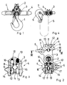
- the component shown in Figures 1-4 has the structure of a double vortex, which essentially consists of an inner part formed by a hook 1, a central part designed as a connecting element 2 and an outer part which forms a carrier 3 which has two shortening devices 4.
- Fig. 2 it is indicated that the hooks 6 can be hung in eyelets 7 to form wreath chains.
- the shortening devices 4 have two intersecting guide slots 8, 9 which form a pull-through opening for the chain strands 5 when two locking bolts 12, 13, which can be displaced against the action of return springs 10 and are connected to one another via a web 11, fully release the guide slot, as is shown in FIG 3 is shown.
- two grooves 14, 15 of the locking bolts 12, 13 coincide with the curves in the end regions of the guide slot 9, while in the locking position, support recesses 16, 17 of the locking bolts 12, 13 come to rest in these regions (cf. FIG. 2 ).
- the carriers of the components according to FIGS. 5-8 have the shape of a disk, which allows a larger number of shortening devices to be accommodated and opens up a wide range of possible uses.
- the carrier 18 of the component according to FIGS. 5 and 6 is equipped with three shortening devices 4, which have the same structure as the shortening devices of the first exemplary embodiment.
- a connecting element 2 designed as a fork head
- a mushroom-shaped connecting element 19 is used here.
- retaining eyelets 20 for hanging hooks of chain strands 5, not shown here are arranged.
- the support 21 of which has four shortening devices 4, two, three and four hangers can be formed as required, i.e. realize all practically sensible combination options.
- the connecting member 22 is not designed as a central part, but as an outer part of the double vortex, as in the previously described embodiments.
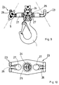
- a carrier 25 is rotatably mounted here on a connecting member 24, the ends of which form upwardly angled slots 26, each of which adjoins a pull-through opening 27.
Abstract
Description
Die Erfindung betrifft ein Bauteil für Kettengehänge mit einem Anschlußorgan für das Ende mindestens eines mit einem Hebezeug verbindbaren Lastaufnahmemittels, einem fluchtend zum Anschlußorgan angeordneten Haken und einem Träger mit Verkürzungsvorrichtungen für Kettenstränge.The invention relates to a component for chain slings with a connecting element for the end of at least one load-carrying means which can be connected to a lifting device, a hook arranged in alignment with the connecting element and a carrier with shortening devices for chain strands.
Aus der BE-A- 496 698 ist ein Bauteil der vorstehenden Art bekannt, bei dem ein tellerförmiger Träger an seinem Umfang mit nach außen offenen radialen Schlitzen und jeweils quer zu diesen Schlitzen verlaufenden Stützmulden für die Rundung eines Kettengliedes versehen ist, das mit einem in den jeweiligen Schlitz eingeführten Kettenglied eines verkürzbaren Kettenstranges verbunden ist. Um den Kettenstrang zu verkürzen, muß er bei diesem Bauteil vom Träger getrennt und erneut wieder eingehängt werden, so daß ein Zusammenhalt des Trägers und der Kettenstränge bei deren Verkürzung nicht gegeben ist und beim Einstellvorgang die Gefahr des Abrutschens eines Kettenstranges insbesondere bei einer Schieflage des Trägers besteht. Nicht zu befriedigen vermag bei dem bekannten Bauteil zudem der Umstand, daß sein Anschlußorgan drehfest mit dem Haken verbunden ist und Anschlußorgan und Haken folglich nicht unabhängig voneinander in unterschiedliche Winkelpositionen gegenüber dem Träger überführbar sind. Bekannt ist außerdem aus der Firmendruckschrift Gü-EHB/f/6.89/Wa der Anmelderin ein als Doppelwirbel ausgebildetes Bauteil für Kettengehänge, dessen Träger mit zwei sich gegenüberliegenden Gabelköpfen zum Anschluß eines Endgliedes jeweils eines kurzen Kettenstranges versehen ist, dessen anderes Endglied mit einer Verkürzungsvorrichtug für jeweils einen zusätzlichen Kettenstrang ausgestattet ist, der an mindestens einem seiner Enden einen weiteren Haken aufweist. Bei Einsatz dieses zweiten bekannten Bauteiles können sich in Fällen Probleme ergeben, in denen die Raumverhältnisse ungünstig sind. Der Grund hierfür besteht darin, daß der Abstand zwischen dem Anschlußorgan für das jeweilige Lastaufnahmemittel und dem weiteren Haken des zusätzlichen Kettenstranges infolge der zwischen die Gabelköpfe und die zusätzlichen Kettenstränge geschalteten kurzen Kettenstränge verhältnismäßig groß ist. Letzteres kann sich insbesondere beim Untertageeinsatz als störend erweisen. Hinzu kommt, daß die unter Verwendung der bekannten Bauteile zusammengestellten Gehänge zwar den Vorteil bieten, daß sie mit unterschiedlichen und austauschbaren Verkürzungsvorrichtungen ausgestattet werden können, daß dieser Vorteil indes mit einer vergleichsweise sperrigen und schweren Bauweise des jeweiligen Gehänges erkauft werden muß.From BE-A-496 698 a component of the above type is known, in which a plate-shaped carrier is provided on its periphery with outwardly open radial slots and each transverse to these slots support troughs for rounding a chain link, which is provided with a the respective slot inserted chain link of a shortenable chain strand is connected. In order to shorten the chain strand, it must be separated from the carrier in this component and hung again, so that there is no cohesion of the carrier and the chain strands when shortening them, and during the adjustment process there is a risk of a chain strand slipping, particularly when the carrier is skewed consists. Also unsatisfactory in the known component is the fact that its connecting element is connected to the hook in a rotationally fixed manner and consequently connecting element and hook cannot be transferred independently of one another into different angular positions with respect to the carrier. It is also known from the company publication Gü-EHB / f / 6.89 / Wa by the applicant a component designed as a double vortex Chain hanger, the carrier of which is provided with two opposing fork heads for connecting one end link each of a short chain strand, the other end link of which is equipped with a shortening device for each additional chain strand, which has a further hook on at least one of its ends. When using this second known component, problems can arise in which the spatial conditions are unfavorable. The reason for this is that the distance between the connecting member for the respective load-carrying means and the further hook of the additional chain strand is relatively large due to the short chain strands connected between the fork heads and the additional chain strands. The latter can prove disruptive, especially when used underground. In addition, the buckets put together using the known components offer the advantage that they can be equipped with different and interchangeable shortening devices, but this advantage must be bought with a comparatively bulky and heavy construction of the respective buckets.
Der Erfindung liegt die Aufgabe zugrunde, ein Bauteil der in Betracht gezogenen Art zu schaffen, das die Vorteile der beiden zuvor beschriebenen Bauteile in sich vereint. Diese Aufgabe wird erfindungsgemäß dadurch gelöst, daß das Bauteil als eine Drehung des Anschlußorganes sowohl gegenüber dem Träger als auch gegenüber dem Haken zulassender Doppelwirbel ausgebildet ist und die Verkürzungsvorrichtungen mit Durchziehöffnungen für die Kettenstränge versehen sind.The invention has for its object to provide a component of the type under consideration, which combines the advantages of the two components described above. This object is achieved in that the component is designed as a rotation of the connecting member both with respect to the support and with respect to the hook double swivels and the shortening devices are provided with pull-through openings for the chain strands.
Durch die Verwendung von Verkürzungsvorrichtungen mit einer Durchziehöffnung sind die Voraussetzungen für eine unverlierbare Verbindung der Kettenstränge mit dem Bauteil geschaffen, indem man die Enden der Kettenstränge mit Organen versieht, die die Durchziehöffnungen nicht passieren können. Die Doppelwirbelausbildung des Bauteiles fördert dessen leichte Handhabbarkeit, indem sie eine schnelle Anpassung der Lage der Kettenstränge an die Anschlußpunkte der jeweils anzuhebenden Last ermöglicht.The use of shortening devices with a pull-through opening creates the conditions for a captive connection of the chain strands to the component by providing the ends of the chain strands with organs that cannot pass through the pull-through openings. The double vortex formation of the component promotes its light weight Manageability by allowing a quick adjustment of the position of the chain strands to the connection points of the load to be lifted.
Weitere Einzelheiten und Merkmale der Erfindung ergeben sich aus der nachstehenden Beschreibung mehrerer in der beigefügten Zeichnung dargestellter Ausführungsbeispiele. Es zeigen:
- Fig. 1
- teilweise im Schnitt eine Seitenansicht eines ersten Bauteiles;
- Fig. 2
- teilweise im Schnitt die Draufsicht auf das Bauteil gemäß Fig. 1;
- Fig. 3
- in vergrößertem Maßstab eine Einzelheit der Verkürzungsvorrichtung des Bauteiles gemäß Fig. 1 und 2;
- Fig. 4
- einen Schnitt längs der Linie IV-IV in Fig. 2;
- Fig. 5
- teilweise im Schnitt eine Seitenansicht eines zweiten Bauteiles;
- Fig. 6
- teilweise im Schnitt die Draufsicht auf das Bauteil gemäß Fig. 5;
- Fig. 7
- teilweise im Schnitt eine Teilseitenansicht eines dritten Bauteiles;
- Fig. 8
- teilweise im Schnitt die Draufsicht auf das Bauteil gemäß Fig. 7;
- Fig. 9
- teilweise im Schnitt die Seitenansicht eines vierten Bauteiles und
- Fig. 10
- die Draufsicht auf das Bauteil gemäß Fig. 9.
- Fig. 1
- partly in section a side view of a first component;
- Fig. 2
- partly in section, the top view of the component according to FIG. 1;
- Fig. 3
- on an enlarged scale a detail of the shortening device of the component according to FIGS. 1 and 2;
- Fig. 4
- a section along the line IV-IV in Fig. 2;
- Fig. 5
- partly in section a side view of a second component;
- Fig. 6
- partly in section, the top view of the component according to FIG. 5;
- Fig. 7
- partly in section a partial side view of a third component;
- Fig. 8
- partly in section, the top view of the component according to FIG. 7;
- Fig. 9
- partly in section the side view of a fourth component and
- Fig. 10
- the top view of the component according to FIG. 9.
Das in den Figuren 1 - 4 dargestellte Bauteil hat den Aufbau eines Doppelwirbels, der im wesentlichen aus einem von einem Haken 1 gebildeten Innenteil, einem als Anschlußorgan 2 ausgebildeten Mittelteil und einem Außenteil besteht, das einen Träger 3 bildet, der zwei Verkürzungsvorrichtungen 4 aufweist. Die Verkürzungsvorrichtungen 4 dienen zur unverlierbaren Aufnahme verkürzbarer Kettenstränge 5, die an mindestens einem Ende mit jeweils einem Haken 6 versehen sind, und deren Teilung kleiner oder gleich t = 3d ist, wobei d das Maß für die Dicke der Kettenglieder ist. In Fig. 2 ist angedeutet, daß sich die Haken 6 zur Kranzkettenbildung in Halteösen 7 einhängen lassen.The component shown in Figures 1-4 has the structure of a double vortex, which essentially consists of an inner part formed by a hook 1, a central part designed as a connecting
Die Verkürzungsvorrichtungen 4 weisen zwei sich kreuzende Führungsschlitze 8,9 auf, die eine Durchziehöffnung für die Kettenstränge 5 bilden, wenn zwei gegen die Wirkung von Rückstellfedern 10 verschiebbare über einen Steg 11 miteinander verbundene Arretierbolzen 12,13 den Führungsschlitz voll freigeben, wie dies in Fig. 3 gezeigt ist. In der Freigabeposition decken sich zwei Nuten 14, 15 der Arretierbolzen 12,13 mit den Rundungen in den Endbereichen des Führungsschlitzes 9, während in der Arretierstellung in diesen Bereichen Stützmulden 16,17 der Arretierbolzen 12,13 zu liegen kommen (vgl. Fig. 2).The
Während der Träger 3 des Bauteiles gemäß den Figuren 1 - 4 stegförmig ist, haben die Träger der Bauteile gemäß den Figuren 5 - 8 die Form einer Scheibe, die die Unterbringung einer größeren Zahl von Verkürzungsvorrichtungen gestattet und vielfältige Einsatzmöglichkeiten eröffnet.While the
Der Träger 18 des Bauteiles gemäß den Figuren 5 und 6 ist mit drei Verkürzungsvorrichtungen 4 ausgestattet, die den gleichen Aufbau haben wie die Verkürzungsvorrichtungen des ersten Ausführungsbeispieles. Anstelle eines als Gabelkopf ausgebildeten Anschlußorganes 2 findet hier ein pilzförmiges Anschlußorgan 19 Verwendung. Zwischen den jeweils aufeinanderfolgenden Verkürzungsvorrichtungen sind Halteösen 20 zum Einhängen hier nicht dargestellter Haken von Kettensträngen 5 angeordnet.The
Mit dem Bauteil gemäß Fig. 7 und 8, dessen Träger 21 vier Verkürzungsvorrichtungen 4 aufweist, lassen sich nach Bedarf Zweier-, Dreier- und Vierergehänge bilden, d.h. alle praktisch sinnvollen Kombinationsmöglichkeiten realisieren. Das Anschlußorgan 22 ist bei diesem Ausführungsbeispiel nicht wie bei den zuvor beschriebenen Ausführungsformen als Mittel-, sondern als Außenteil des Doppelwirbels ausgebildet.7 and 8, the
Ein besonders einfache Verkürzungsvorrichtungen 23 aufweisendes Bauteil zeigen die Fig. 9 und 10. Auf einem Anschlußorgan 24 ist hier ein Träger 25 drehbar gelagert, dessen Enden nach oben abgewinkelte Schlitze 26 bilden, die sich an jeweils eine Durchziehöffnung 27 anschließen.9 and 10 show a particularly
Claims (9)
- A component for a chain suspension comprising means (2; 19; 22) for connecting the end of at least one load-lifting member to a lifting apparatus, a hook (1) disposed in line with the connecting means (2; 19; 22), and a holder (3; 18; 21; 25) with shortening means (4; 23) for chain strands (5), characterised in that the component is a double swivel permitting rotation of the connecting member (2; 19; 22) relative to the holder (3; 18; 21; 25) and also relative to the hook (1), and the shortening devices (4; 23) are formed with openings (8; 9; 27) for pulling through the chain strands (5).
- A component according to claim 1, characterised in that the holder (3) comprises eyelets (7; 20) into which hooks disposed at the ends of the shortenable chain strands (5) can be suspended to form a chain-ring arrangement.
- A component according to claim 1 or claim 2, characterised in that the holder (18; 21) has at least three shortening devices (4).
- A component according to any one of claims 1 to 3, characterised in that the holder (18; 21) is disc-shaped.
- A component according to claim 4, characterised in that an eyelet (7; 20) for suspending a hook (6) is disposed between each pair of successive shortening devices (4).
- A component according to any one of claims 1 to 5, characterised in that the shortening devices (4) each comprise two intersecting guide slots (8, 9) for the chain strands (5) and a respective one (9) of the two guide slots (8, 9) is associated with at least one bolt (12, 13) for locking at least one link of one chain strand (5), the bolt being movable against the action of at least one restoring spring (10).
- A component according to any one of claims 1 to 5, characterised in that each shortening device (23) is formed with a locking slot (26) adjacent to the pull-through opening (27).
- A component according to claim 7, characterised in that the locking slots (26) are bent upwards relative to the pull-through opening (27).
- A component according to claim 7 or claim 8, characterised in that the pull-through openings (17) are disposed between the locking slots (26) and a central annular part of the holder (25).
Applications Claiming Priority (2)
| Application Number | Priority Date | Filing Date | Title |
|---|---|---|---|
| DE3938984A DE3938984C1 (en) | 1989-11-23 | 1989-11-23 | |
| DE3938984 | 1989-11-23 |
Publications (2)
| Publication Number | Publication Date |
|---|---|
| EP0431713A1 EP0431713A1 (en) | 1991-06-12 |
| EP0431713B1 true EP0431713B1 (en) | 1994-06-08 |
Family
ID=6394143
Family Applications (1)
| Application Number | Title | Priority Date | Filing Date |
|---|---|---|---|
| EP90250290A Expired - Lifetime EP0431713B1 (en) | 1989-11-23 | 1990-11-23 | Construction element for chain suspensions |
Country Status (3)
| Country | Link |
|---|---|
| EP (1) | EP0431713B1 (en) |
| AT (1) | ATE106848T1 (en) |
| DE (1) | DE3938984C1 (en) |
Families Citing this family (1)
| Publication number | Priority date | Publication date | Assignee | Title |
|---|---|---|---|---|
| EP3395743A1 (en) * | 2017-04-25 | 2018-10-31 | pewag austria GmbH | Contraction device for a link chain |
Family Cites Families (8)
| Publication number | Priority date | Publication date | Assignee | Title |
|---|---|---|---|---|
| US2519460A (en) * | 1948-11-22 | 1950-08-22 | Young Iron Works | Butt-rigging swivel |
| BE496698A (en) * | 1949-08-06 | |||
| US4060269A (en) * | 1975-04-15 | 1977-11-29 | Werner Rieger | Equalizing head for chain slings |
| FR2396889A2 (en) * | 1977-07-07 | 1979-02-02 | Stas Soc Tech Access Spec | LIFTING RING FOR CHAIN SLING |
| DE3403343A1 (en) * | 1984-02-01 | 1985-08-08 | Passing Maschinenbau GmbH & Co KG, 4350 Recklinghausen | Hook-link chain for suspended railways in underground operation |
| DE8518630U1 (en) * | 1985-06-27 | 1985-08-29 | Fa. August Thiele, 5860 Iserlohn | Chain locking element, especially chain stoppers, for round link chains |
| DE3723173A1 (en) * | 1987-07-14 | 1989-01-26 | Erlau Ag Eisen Drahtwerk | Overload monitoring device for chains |
| JPH01209297A (en) * | 1988-02-16 | 1989-08-23 | Masakatsu Makino | Sling |
-
1989
- 1989-11-23 DE DE3938984A patent/DE3938984C1/de not_active Expired - Fee Related
-
1990
- 1990-11-23 AT AT90250290T patent/ATE106848T1/en not_active IP Right Cessation
- 1990-11-23 EP EP90250290A patent/EP0431713B1/en not_active Expired - Lifetime
Also Published As
| Publication number | Publication date |
|---|---|
| DE3938984C1 (en) | 1991-05-29 |
| ATE106848T1 (en) | 1994-06-15 |
| EP0431713A1 (en) | 1991-06-12 |
Similar Documents
| Publication | Publication Date | Title |
|---|---|---|
| DE2055253C3 (en) | Lashing or sling chain | |
| DE2819986C2 (en) | Lifting and transport gear with compensating rocker, in particular for use with chain sling harnesses and with lifting strap arrangements | |
| EP1223139B1 (en) | Device for lifting a load | |
| DE1625874A1 (en) | Snap hook | |
| EP0431713B1 (en) | Construction element for chain suspensions | |
| DE4237155C1 (en) | Movement device for scaffolding units - involves suspension borne by crane rope having at last two belts engaging with their free ends in suspension eyelets of scaffolding unit | |
| DE3213473A1 (en) | LOSSABLE CONNECTION OR FASTENING DEVICE | |
| DE2732246A1 (en) | HANGING HEAD FOR LOAD STRAND-ORIENTED SINGLE CHAIN SYSTEMS | |
| EP3663608A1 (en) | Chain suspension for suspending a load on a crane hook | |
| DE2059030B2 (en) | Grappling hook | |
| DE2619732C2 (en) | Connection device for a lashing line | |
| AT391006B (en) | CONNECTOR FOR CHAIN HANGERS | |
| DE3235300C2 (en) | Arrangement for connecting components as well as tensioning and / or control devices of lifting or lashing arrangements with belts | |
| EP0104135B1 (en) | Assembly for connecting parts as well as tensioning and/or control devices of hoisting and/or lashing arrangements with belts. | |
| EP1300360A1 (en) | Load engaging hook with shortening claw | |
| DE2546144C2 (en) | Attachment harness for channel sections | |
| EP0105022A2 (en) | Connecting assembly for load-lifting devices | |
| DE2411725A1 (en) | Shackle for attaching chains to crane hooks - has flat surface for inscription of maximum safe load | |
| DE2539513C3 (en) | Hook tackle | |
| EP2978705B1 (en) | Rocker arm for a multi-strand attachment means | |
| DE2819987A1 (en) | Rubbish skip handling tackle - has chains each with forged eye fixed at bottom by bolt | |
| DE19900486C2 (en) | Hanger | |
| DE2321937C2 (en) | Return device for long wood | |
| EP0163909A2 (en) | Load lifting device | |
| DE1228187B (en) | Attachment of garland-shaped support roller sets to the longitudinal beams of a conveyor belt system |
Legal Events
| Date | Code | Title | Description |
|---|---|---|---|
| PUAI | Public reference made under article 153(3) epc to a published international application that has entered the european phase |
Free format text: ORIGINAL CODE: 0009012 |
|
| AK | Designated contracting states |
Kind code of ref document: A1 Designated state(s): AT FR GB IT SE |
|
| 17P | Request for examination filed |
Effective date: 19911211 |
|
| 17Q | First examination report despatched |
Effective date: 19921007 |
|
| GRAA | (expected) grant |
Free format text: ORIGINAL CODE: 0009210 |
|
| AK | Designated contracting states |
Kind code of ref document: B1 Designated state(s): AT FR GB IT SE |
|
| PG25 | Lapsed in a contracting state [announced via postgrant information from national office to epo] |
Ref country code: IT Free format text: LAPSE BECAUSE OF FAILURE TO SUBMIT A TRANSLATION OF THE DESCRIPTION OR TO PAY THE FEE WITHIN THE PRESCRIBED TIME-LIMIT;WARNING: LAPSES OF ITALIAN PATENTS WITH EFFECTIVE DATE BEFORE 2007 MAY HAVE OCCURRED AT ANY TIME BEFORE 2007. THE CORRECT EFFECTIVE DATE MAY BE DIFFERENT FROM THE ONE RECORDED. Effective date: 19940608 Ref country code: FR Effective date: 19940608 |
|
| REF | Corresponds to: |
Ref document number: 106848 Country of ref document: AT Date of ref document: 19940615 Kind code of ref document: T |
|
| PG25 | Lapsed in a contracting state [announced via postgrant information from national office to epo] |
Ref country code: SE Effective date: 19940908 |
|
| GBT | Gb: translation of ep patent filed (gb section 77(6)(a)/1977) |
Effective date: 19940915 |
|
| EN | Fr: translation not filed | ||
| PGFP | Annual fee paid to national office [announced via postgrant information from national office to epo] |
Ref country code: GB Payment date: 19941109 Year of fee payment: 5 |
|
| PGFP | Annual fee paid to national office [announced via postgrant information from national office to epo] |
Ref country code: AT Payment date: 19941122 Year of fee payment: 5 |
|
| PLBE | No opposition filed within time limit |
Free format text: ORIGINAL CODE: 0009261 |
|
| STAA | Information on the status of an ep patent application or granted ep patent |
Free format text: STATUS: NO OPPOSITION FILED WITHIN TIME LIMIT |
|
| 26N | No opposition filed | ||
| PG25 | Lapsed in a contracting state [announced via postgrant information from national office to epo] |
Ref country code: GB Effective date: 19951123 Ref country code: AT Effective date: 19951123 |
|
| GBPC | Gb: european patent ceased through non-payment of renewal fee |
Effective date: 19951123 |