EP0431229B1 - Deflection yoke assembly for cathode ray tube and liner for the same - Google Patents
Deflection yoke assembly for cathode ray tube and liner for the same Download PDFInfo
- Publication number
- EP0431229B1 EP0431229B1 EP89403411A EP89403411A EP0431229B1 EP 0431229 B1 EP0431229 B1 EP 0431229B1 EP 89403411 A EP89403411 A EP 89403411A EP 89403411 A EP89403411 A EP 89403411A EP 0431229 B1 EP0431229 B1 EP 0431229B1
- Authority
- EP
- European Patent Office
- Prior art keywords
- studs
- combination
- crt
- liner
- sleeves
- Prior art date
- Legal status (The legal status is an assumption and is not a legal conclusion. Google has not performed a legal analysis and makes no representation as to the accuracy of the status listed.)
- Expired - Lifetime
Links
- 239000000463 material Substances 0.000 claims description 5
- 230000013011 mating Effects 0.000 claims description 5
- 239000004033 plastic Substances 0.000 claims description 4
- 101150097247 CRT1 gene Proteins 0.000 description 3
- 239000000853 adhesive Substances 0.000 description 3
- 230000001070 adhesive effect Effects 0.000 description 3
- 230000000712 assembly Effects 0.000 description 2
- 238000000429 assembly Methods 0.000 description 2
- 239000003989 dielectric material Substances 0.000 description 2
- 238000004519 manufacturing process Methods 0.000 description 2
- 230000004323 axial length Effects 0.000 description 1
- 238000010586 diagram Methods 0.000 description 1
- 229920001971 elastomer Polymers 0.000 description 1
- 239000000806 elastomer Substances 0.000 description 1
- 238000010894 electron beam technology Methods 0.000 description 1
- 229920006332 epoxy adhesive Polymers 0.000 description 1
- 230000001815 facial effect Effects 0.000 description 1
- 239000011521 glass Substances 0.000 description 1
- 230000007246 mechanism Effects 0.000 description 1
- 238000000034 method Methods 0.000 description 1
- 239000002991 molded plastic Substances 0.000 description 1
- 230000000717 retained effect Effects 0.000 description 1
- 238000003466 welding Methods 0.000 description 1
- 238000004804 winding Methods 0.000 description 1
Images



Classifications
-
- H—ELECTRICITY
- H01—ELECTRIC ELEMENTS
- H01J—ELECTRIC DISCHARGE TUBES OR DISCHARGE LAMPS
- H01J29/00—Details of cathode-ray tubes or of electron-beam tubes of the types covered by group H01J31/00
- H01J29/46—Arrangements of electrodes and associated parts for generating or controlling the ray or beam, e.g. electron-optical arrangement
- H01J29/70—Arrangements for deflecting ray or beam
-
- H—ELECTRICITY
- H01—ELECTRIC ELEMENTS
- H01J—ELECTRIC DISCHARGE TUBES OR DISCHARGE LAMPS
- H01J29/00—Details of cathode-ray tubes or of electron-beam tubes of the types covered by group H01J31/00
- H01J29/46—Arrangements of electrodes and associated parts for generating or controlling the ray or beam, e.g. electron-optical arrangement
- H01J29/82—Mounting, supporting, spacing, or insulating electron-optical or ion-optical arrangements
- H01J29/823—Mounting, supporting, spacing, or insulating electron-optical or ion-optical arrangements around the neck of the tube
- H01J29/826—Deflection arrangements
Definitions
- the field of the present invention relates to deflection yoke assemblies, and more particularly to such assemblies including adjustable screws or bolts about the front face or bezel of the deflection yoke lining for adjusting the alignment of the deflection yoke to its associated cathode ray tube (CRT).
- CRT cathode ray tube
- cantilever clamps are included between the cone of the CRT and the mounting ring, which cantilevers are adjustable within a range for axially adjusting the deflection assembly relative to the longitudinal axis of the CRT, whereafter screws between the cantilever member and the ring of the deflection yoke are tightened.
- springs are positioned between the ring and the deflection yoke for forcing the ring forward against the cone of the CRT, whereby the ring is free to move axially relative to the deflection yoke and CRT, and also to swivel into a desired alignment, whereafter the assembly is locked into position.
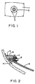
- the German patent DE 3010262 entitled “Method for the Aligning and Fastening of a Deflection Coil Arrangement” teaches as shown in Figure 1 hereof, the mounting of a deflection coil 2 upon a color cathode ray tube or CRT 1, with three adjustable fastening sites 3.
- the mounting portion 5 of a deflection coil includes a threaded insert 7, which is inserted into a hole through a circumferential hole in the forward portion of the mounting portion 5 of the deflection coil.
- a hollow bolt 6 is screwed through the threaded insert 7, causing the threaded insert 7 to expand and become wedged in the opening of the mounting portion 5.
- the hollow bolt 6 at the mounting sites 3 are adjustably screwed against the outside of the tube wall 4 for axially aligning the deflection coil on the CRT 1.
- an adhesive 9 is injected through the hollow bolts to fill the area between the tube wall 4 and the inner space of a collar 8 used to contain the adhesive.
- the adhesive locks the bolt into position, for retaining the alignment of the deflection coil 2 to the CRT 1. Note that only a small portion of the front of the hollow bolt 6 makes contact with the tube wall 4.
- Another object of -the invention is to provide simplification of the fabrication and assembly of an improved yoke assembly.
- Another object of the invention is to provide a simplified design for a deflection yoke assembly for facilitating the mounting of hollow threaded bolts to the assembly.
- a deflection yoke assembly including a mounting ring or bezel having four inclined semicircular or split tubular-like mounting studs or bosses arranged about the circumference of the mounting ring, for receiving in each inclined mounting stud a threaded sleeve having securing and indexing means about its outer wall, for permitting alignment via mating with indexing means on an associated stud, and ultrasonic bonding of the sleeve to its associated inclined mounting stud. Hollow threaded bolts are screwed into each one of the threaded mounting sleeves.
- the frontmost portion of the hollow bolts include contact head means for contacting the surface of the cone of the associated CRT at substantially a 90° angle, with substantially the entire portion of the contact head means contacting the cone.
- the back end or opposite end of the hollow bolt includes slots for receiving a tool for permitting the bolt to be adjustably turned in and out of its associated threaded sleeve for axially adjusting the deflection yoke to the CRT.
- a deflection yoke assembly for a cathode ray tube comprising a truncated cone-shaped liner for mounting over the rear diverging walls and neck of said CRT, a plurality of substantially semicircular tubular-like studs mounted spaced apart about the outside circumference of a ring-like front bezel of said liner and a plurality of internally threaded cylindrical like sleeves adapted for being rigidly mounted partially within and upon associated ones of said plurality of studs.
- the present invention also provides a truncated cone shaped liner for a deflection yoke assembly of cathode ray tube (CRT), comprising, a front bezel formed via a band-like ring having a width parallel to the central longitudinal axis of said liner, a plurality of generally semicircular tubular or channel-like studs mounted spaced apart about the outside width of said front bezel, each stud being inclined at an angle predetermined for causing the central axis thereof to intercept an outside wall of the cone of an associated CRT at approximately 90°, said plurality of studs each including a longitudinal keyway through the center of an inside face, and at least two spaced apart notches along each of opposing top edges, a plurality of internally threaded hollow cylindrical-like sleeves each having at least two pairs of standoffs on opposing sides for index mating in the notches along the top edges of an associated mounting stud, said plurality of sleeves each further including about their outside walls, opposing longitudinal ribs lying in a plane per
- a prior art deflection yoke assembly 20 includes a forwandmost mounting ring or bezel 22 including four inclined mounting studs 24 substantially equally spaced from one another about the outer circumference of the mounting ring 22, in this example.
- hollow bolts 26 are threadably mounted in the mounting studs 24.
- the front or forward ends of the bolts 26 each include a contact head 28 for contacting the cone of an associated CRT.
- Windings 30 of the deflection coil assembly 20 as shown, can be of any desired pattern.
- the particular wiring pattern shown herein is for purposes of illustration only, and has no relevance to the present invention.
- the prior art deflection yoke assembly 20 is shown mounted on the cone 32 of an associated CRT. Also shown affixed to the deflection yoke or coil assembly 20 are a standoff panel 34, and a wiring terminal ring 36 at the rear portion thereof. A sheath beam bender 38 is also shown, along with the rearmost portion 40 of the CRT. Note that the angle of the inclined mounting sleeves 24 is predetermined to insure that the contact heads 28 of the hollow bolts 26 make contact with a maximum area of the cone 32 of the associated CRT.
- the contact head 28 of a hollow bolt 26 has a face that is at 90° to the longitudinal axis of the associated hollow bolt 26, the angle of the mounting sleeves 24 are such that the longitudinal axis of the hollow bolt 26 is perpendicular to the point where the axis intersects the wall of the cone 32. In this manner, highly accurate alignment of the deflection yoke 20 to the CRT is provided. Such positioning and alignment of the bolts 26 or similar bolts is retained in the present invention, as described below.
- the hollow bolts 26 used in one embodiment of the invention include a back end 42 adapted for receiving a tool for turning the bolt 26, and an outwardly flaring saucerlike contact head 44.
- the front of the contact head 44 includes a cap-like member 46 fabricated from an elastomer such as a plastic material, for contacting the typically glass surface of the cone 32, for example.
- the hollow bolt 26 is fabricated from a dielectric material, such as a rigid plastic material, for example.
- U-shaped cutout portions 48 (four are shown in this example) are provided equally spaced about the outer circumferential portion of the contact head 44, as shown. The cutouts 48 permit a spring-like action to be provided by the outer portions of the contact head 44 contacting the cone 32.
- the threaded sleeves 50 are fabricated apart from the liner 22, and when mounted in the semicircular studs or bosses 92, appear as shown in the pictorial of Figure 17.
- the studs 92 are inclined in a similar manner to the studs 24 of the prior art deflection yoke assembly 20.
- Other features of the liner 90 for yoke assembly include ribs 94, 96, and 98.
- the inclined semicircular studs 92 include on each side edge notches or notch-like recesses 100, and a centrally located keyway 102, for indexing with standoffs 54, and one of the keys 51 of sleeves 50, respectively.
- the sleeves 50 which include internal threads for receiving a hollow bolt 26 or 52, also include a band-like flange 53 about their front faces, and another band-like flange 55 located slightly inward from their rear faces 57.
- the front flange 53 and rear flange 55 of a sleeve 50 have their immediately opposing inside facial portions distanced from one another a length that is only slightly greater than the axial length of the semicircular studs 92. In this manner, when a threaded sleeve 50 is pressed into an associated inclined semicircular mounting sleeve 92, it will be properly aligned with and fit snugly into the stud 92. Ultrasonic welding or appropriate epoxy adhesives may be used to rigidly secure the threaded sleeves 50 to their associated inclined semicircular mounting studs 92.
- the liner 90 of the present deflection coil assembly is molded from a dielectric material, such as a plastic material, in one piece with the semicircular mounting studs 92.
- the liner 90 can be dimensioned for accommodating any size yoke.
- the adjustment or hollow alignment bolts 26 of Figures 5 and 6 are in one embodiment of the invention screwed into the threaded sleeves 50 affixed to associated mounting studs 92.
- hollow bolts 52 (see Figure 8) are screwed into the threaded sleeves 50.
- the alternative hollow bolts 52 are described in detail below, as are the hollow bolts 26.
- the threaded inserts 50 include the two pairs of standoffs 54 on immediately opposite sides of the threaded insert 50.
- Two other pairs of standoffs 56 are located on opposite sides of the top and bottom portions of a threaded insert 50, as shown in Figures 10A and 10B.
- the standoffs 54 are in a plane that is perpendicular to the planes of the standoffs 56.
- Female threads 58 are provided within the inserts 50, as shown.
- the hollow bolts 26 are shown in detail. Note the cap stud 60 at the front portion of the bolt 26, of this embodiment, for receiving the elastic cap 28 (see Figure 3). Also note, in Figure 13, the two pairs of opposing slots 64 for receiving a tool for turning a bolt 26 threaded into an associated mounting stud 24.
- an alternative adjustable or hollow bolt configuration 52 is shown.
- the bolt 52 is fabricated in one piece from a molded plastic material, for example.
- the front of the bolt includes a contact head 70 connected by elastic V-springs 72 to the front portion of a bridge segment 74.
- a circular collar 76 is located immediately behind the bridge segment 74.
- Threads 78 are provided about a substantial portion of the body of the bolt 52 behind the collar 76.
- the center of the bolt 52 is hollow cavity 80 that is cylindrical in shape.
- Two pairs of opposing slots 82 located centrally at the rear of bolt 52, as shown in Figure 16, are for receiving a tool (not shown) for turning bolt 52 into and out of an associated threaded sleeve 50.
Landscapes
- Vessels, Lead-In Wires, Accessory Apparatuses For Cathode-Ray Tubes (AREA)
- Manufacture Of Electron Tubes, Discharge Lamp Vessels, Lead-In Wires, And The Like (AREA)
Abstract
Description
- The field of the present invention relates to deflection yoke assemblies, and more particularly to such assemblies including adjustable screws or bolts about the front face or bezel of the deflection yoke lining for adjusting the alignment of the deflection yoke to its associated cathode ray tube (CRT).
- The importance of providing a deflection yoke assembly with mechanisms for permitting the yoke assembly to be adjusted relative to its orientation to an associated CRT upon which it is mounted is well known in the art. For example, U.K. Patent n° 1,586,100, entitled "Mounting and Adjusting a Deflection-Coil Holder for a Colour Picture Tube" teaches the use of a
mounting member 3 rigidly connected to the conical portion at the back of a cathode ray tube 1. A deflection coil holder 2 is adjustably connected to the mounting member via holes through a mounting flange of the deflection coil holder 2, through whichexpandable dowels 6 are inserted to screw into sleeves 4 of themounting member 3. Thedowels 6, which apparently number at least 3, permit the deflection coil holder 2 to be adjusted relative to the CRT, for obtaining optimum convergence of the electron beams of a color CRT, for example, to optimize the picture quality. - Brunn et al., US 4,285,013, entitled "Mounting Assembly for a Deflection Yoke", teaches the use of a ring-like member about the front portion of a deflection yoke assembly as a supporting part at the expanding end of the deflection yoke. The ring is freely moveable on the cone of the CRT, and mounted on the deflection yoke for providing axial adjustment thereof, whereafter the assembly is locked in position on the CRT. In one embodiment, the ring is fixed to the deflection yoke via a plurality of screws about the circumference of the ring. In another embodiment, cantilever clamps are included between the cone of the CRT and the mounting ring, which cantilevers are adjustable within a range for axially adjusting the deflection assembly relative to the longitudinal axis of the CRT, whereafter screws between the cantilever member and the ring of the deflection yoke are tightened. In another embodiment, springs are positioned between the ring and the deflection yoke for forcing the ring forward against the cone of the CRT, whereby the ring is free to move axially relative to the deflection yoke and CRT, and also to swivel into a desired alignment, whereafter the assembly is locked into position.
- The German patent DE 3010262, entitled "Method for the Aligning and Fastening of a Deflection Coil Arrangement", teaches as shown in Figure 1 hereof, the mounting of a deflection coil 2 upon a color cathode ray tube or CRT 1, with three
adjustable fastening sites 3. As shown in Figure 2, hereof, themounting portion 5 of a deflection coil includes a threaded insert 7, which is inserted into a hole through a circumferential hole in the forward portion of themounting portion 5 of the deflection coil. Ahollow bolt 6 is screwed through the threaded insert 7, causing the threaded insert 7 to expand and become wedged in the opening of themounting portion 5. Thehollow bolt 6 at themounting sites 3 are adjustably screwed against the outside of the tube wall 4 for axially aligning the deflection coil on the CRT 1. After aligning the deflection coil 2 to the CRT, an adhesive 9 is injected through the hollow bolts to fill the area between the tube wall 4 and the inner space of a collar 8 used to contain the adhesive. Upon setting, the adhesive locks the bolt into position, for retaining the alignment of the deflection coil 2 to the CRT 1. Note that only a small portion of the front of thehollow bolt 6 makes contact with the tube wall 4. Also note that reliance of retaining the threaded inserts 7 in the holes thorough the front bezel of themounting portion 5 of the deflection coil may cause assembly problems, whereby the threaded inserts 7 prior to such wedging upon receiving ahollow bolt 6, may tend to move out of the hole or partially out of the hole of the bezel. Also, if these inserts 7 are cylindrical, they may spin when thehollow bolts 6 are first screwed into the inserts 7, making assembly difficult. - It is an object of the invention to provide an improved deflection yoke assembly.
- Another object of -the invention is to provide simplification of the fabrication and assembly of an improved yoke assembly.
- Another object of the invention is to provide a simplified design for a deflection yoke assembly for facilitating the mounting of hollow threaded bolts to the assembly.
- With the problems in the prior art in mind, these and other objects of the invention are provided in a deflection yoke assembly including a mounting ring or bezel having four inclined semicircular or split tubular-like mounting studs or bosses arranged about the circumference of the mounting ring, for receiving in each inclined mounting stud a threaded sleeve having securing and indexing means about its outer wall, for permitting alignment via mating with indexing means on an associated stud, and ultrasonic bonding of the sleeve to its associated inclined mounting stud. Hollow threaded bolts are screwed into each one of the threaded mounting sleeves. The frontmost portion of the hollow bolts include contact head means for contacting the surface of the cone of the associated CRT at substantially a 90° angle, with substantially the entire portion of the contact head means contacting the cone. The back end or opposite end of the hollow bolt includes slots for receiving a tool for permitting the bolt to be adjustably turned in and out of its associated threaded sleeve for axially adjusting the deflection yoke to the CRT.
- In accordance with the present invention there is provided In a deflection yoke assembly for a cathode ray tube (CRT), the combination comprising a truncated cone-shaped liner for mounting over the rear diverging walls and neck of said CRT, a plurality of substantially semicircular tubular-like studs mounted spaced apart about the outside circumference of a ring-like front bezel of said liner and a plurality of internally threaded cylindrical like sleeves adapted for being rigidly mounted partially within and upon associated ones of said plurality of studs.
- The present invention also provides a truncated cone shaped liner for a deflection yoke assembly of cathode ray tube (CRT), comprising, a front bezel formed via a band-like ring having a width parallel to the central longitudinal axis of said liner, a plurality of generally semicircular tubular or channel-like studs mounted spaced apart about the outside width of said front bezel, each stud being inclined at an angle predetermined for causing the central axis thereof to intercept an outside wall of the cone of an associated CRT at approximately 90°, said plurality of studs each including a longitudinal keyway through the center of an inside face, and at least two spaced apart notches along each of opposing top edges, a plurality of internally threaded hollow cylindrical-like sleeves each having at least two pairs of standoffs on opposing sides for index mating in the notches along the top edges of an associated mounting stud, said plurality of sleeves each further including about their outside walls, opposing longitudinal ribs lying in a plane perpendicular to the plane intercepting said standoffs, said ribs being parallel to the longitudinal axis of their associated sleeve, with either one of said ribs serving as a key to mate with said keyway of an associated stud; said plurality of sleeves each further including a first band-like collar at one end, and a second band-like collar inward of the opposite end of said sleeve, said first and second collars each projecting away from the outside wall of their associated sleeve, and being spaced apart from one another a distance substantially the same as the length of each one of said plurality of studs, for providing a snug fit therebetween.
- Various embodiments of the present invention are described below with reference to the accompanying drawings, wherein like items are identified the same reference designation, in which:
- Figures 1 and 2 are identical to Figures 1 and 2 including the same reference designations, of German DE 3010262.
- Figure 3 is a front pictorial view of a prior art deflection yoke assembly.
- Figure 4 is a pictorial side view of the deflection yoke assembly of Figure 3 as mounted on a CRT.
- Figure 5 is a side pictorial view of a hollow adjusting or alignment bolt used in one embodiment of the invention.
- Figure 6 is a front pictorial view of the hollow adjusting bolt of Figure 5.
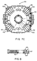
- Figure 7A, 7B and 7C are side, front, and rear elevational views of a deflection yoke assembly of one embodiment of the invention without threaded sleeves secured to their associated inclined mounting studs.
- Figure 8 is a side pictorial exploded assembly diagram of a hollow adjusting bolt and threaded sleeve of an embodiment of the invention.
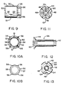
- Figure 9 is a side elevation view of the threaded sleeve of Figure 8.
- Figure 10A is a plan front elevation view of the threaded sleeve of Figure 9.
- Figure 10B is a plan rear elevation view of the threaded sleeve.
- Figure 11 is a plan front view of a hollow bolt of another embodiment of the invention.
- Figure 12 is a side-elevation view in partial section of the hollow bolt of Figure 11;
- Figure 13 is a partial plan rear view of the hollow bolt of Figures 11 and 12.
- Figure 14 is a plan front view of a hollow bolt of another embodiment of the invention.
- Figure 15 is a side-elevation view in cross section of the hollow bolt of Figure 14.
- Figure 16 is a plan rear view of the hollow bolt of Figures 14 and 15.
- Figure 17 is a front pictorial view of one embodiment of the invention.
- With reference to Figure 3, a prior art
deflection yoke assembly 20, includes a forwandmost mounting ring orbezel 22 including fourinclined mounting studs 24 substantially equally spaced from one another about the outer circumference of themounting ring 22, in this example. As will be described in greater detail below,hollow bolts 26 are threadably mounted in themounting studs 24. The front or forward ends of thebolts 26 each include acontact head 28 for contacting the cone of an associated CRT.Windings 30 of thedeflection coil assembly 20 as shown, can be of any desired pattern. The particular wiring pattern shown herein is for purposes of illustration only, and has no relevance to the present invention. - In Figure 4, the prior art
deflection yoke assembly 20 is shown mounted on thecone 32 of an associated CRT. Also shown affixed to the deflection yoke orcoil assembly 20 are astandoff panel 34, and awiring terminal ring 36 at the rear portion thereof. Asheath beam bender 38 is also shown, along with therearmost portion 40 of the CRT. Note that the angle of theinclined mounting sleeves 24 is predetermined to insure that thecontact heads 28 of thehollow bolts 26 make contact with a maximum area of thecone 32 of the associated CRT. Since thecontact head 28 of ahollow bolt 26 has a face that is at 90° to the longitudinal axis of the associatedhollow bolt 26, the angle of themounting sleeves 24 are such that the longitudinal axis of thehollow bolt 26 is perpendicular to the point where the axis intersects the wall of thecone 32. In this manner, highly accurate alignment of thedeflection yoke 20 to the CRT is provided. Such positioning and alignment of thebolts 26 or similar bolts is retained in the present invention, as described below. - The
hollow bolts 26 used in one embodiment of the invention, as shown in Figures 5 and 6, as will be described in greater detail below, include aback end 42 adapted for receiving a tool for turning thebolt 26, and an outwardly flaringsaucerlike contact head 44. The front of thecontact head 44 includes a cap-like member 46 fabricated from an elastomer such as a plastic material, for contacting the typically glass surface of thecone 32, for example. Thehollow bolt 26 is fabricated from a dielectric material, such as a rigid plastic material, for example. U-shaped cutout portions 48 (four are shown in this example) are provided equally spaced about the outer circumferential portion of thecontact head 44, as shown. Thecutouts 48 permit a spring-like action to be provided by the outer portions of thecontact head 44 contacting thecone 32. - It has been recognized that the manufacturing costs and time for the
yoke assembly 20 of Figures 3 and 4 could be reduced, if a design change is made to overcome the problems with fabricating the threadedstuds 24. To accomplish this improvement, it has been conceived the onepiece liner 90 shown in Figures 7A, 7B and 7C. Theliner 90 is substantially similar to the liner orbezel 22 of the prior artdeflection yoke assembly 20. One major difference, in a preferred embodiment of the present invention, is the provision of inclined semicircular or split tubular-like studs orbosses 92 for receiving a threadedsleeve 50 as shown in Figures 8, 9, 10A, and 10B, the latter being described in detail below. The threadedsleeves 50 are fabricated apart from theliner 22, and when mounted in the semicircular studs orbosses 92, appear as shown in the pictorial of Figure 17. Note that thestuds 92 are inclined in a similar manner to thestuds 24 of the prior artdeflection yoke assembly 20. Other features of theliner 90 for yoke assembly includeribs semicircular studs 92 include on each side edge notches or notch-like recesses 100, and a centrally locatedkeyway 102, for indexing withstandoffs 54, and one of thekeys 51 ofsleeves 50, respectively. Note also that thesleeves 50 which include internal threads for receiving ahollow bolt like flange 53 about their front faces, and another band-like flange 55 located slightly inward from their rear faces 57. Thefront flange 53 andrear flange 55 of asleeve 50 have their immediately opposing inside facial portions distanced from one another a length that is only slightly greater than the axial length of thesemicircular studs 92. In this manner, when a threadedsleeve 50 is pressed into an associated inclined semicircular mountingsleeve 92, it will be properly aligned with and fit snugly into thestud 92. Ultrasonic welding or appropriate epoxy adhesives may be used to rigidly secure the threadedsleeves 50 to their associated inclined semicircular mountingstuds 92. - In a preferred embodiment of the invention, the
liner 90 of the present deflection coil assembly is molded from a dielectric material, such as a plastic material, in one piece with the semicircular mountingstuds 92. Theliner 90 can be dimensioned for accommodating any size yoke. The adjustment orhollow alignment bolts 26 of Figures 5 and 6 are in one embodiment of the invention screwed into the threadedsleeves 50 affixed to associated mountingstuds 92. In an alternative embodiment of the invention, hollow bolts 52 (see Figure 8) are screwed into the threadedsleeves 50. The alternativehollow bolts 52 are described in detail below, as are thehollow bolts 26. The threaded inserts 50, as shown in Figures 9, 10A and 10B, as previously described, include the two pairs ofstandoffs 54 on immediately opposite sides of the threadedinsert 50. Two other pairs ofstandoffs 56 are located on opposite sides of the top and bottom portions of a threadedinsert 50, as shown in Figures 10A and 10B. Note that thestandoffs 54 are in a plane that is perpendicular to the planes of thestandoffs 56.Female threads 58 are provided within theinserts 50, as shown. - With reference to Figures 11, 12 and 13, the
hollow bolts 26 are shown in detail. Note thecap stud 60 at the front portion of thebolt 26, of this embodiment, for receiving the elastic cap 28 (see Figure 3). Also note, in Figure 13, the two pairs of opposingslots 64 for receiving a tool for turning abolt 26 threaded into an associated mountingstud 24. - In another embodiment of the invention, as shown in detail in Figures 14, 15 and 16, an alternative adjustable or
hollow bolt configuration 52 is shown. Thebolt 52 is fabricated in one piece from a molded plastic material, for example. The front of the bolt includes acontact head 70 connected by elastic V-springs 72 to the front portion of abridge segment 74. Acircular collar 76 is located immediately behind thebridge segment 74.Threads 78 are provided about a substantial portion of the body of thebolt 52 behind thecollar 76. The center of thebolt 52 ishollow cavity 80 that is cylindrical in shape. Two pairs of opposingslots 82, located centrally at the rear ofbolt 52, as shown in Figure 16, are for receiving a tool (not shown) for turningbolt 52 into and out of an associated threadedsleeve 50.
Claims (10)
- Deflection yoke assembly for a cathode ray tube (CRT), a combination comprising a truncated cone-shaped liner (90) for mounting over the rear diverging walls and neck of said CRT, said liner having a ring-like front bezel comprising a plurality of substantially semicircular tubular studs (92) mounted spaced apart about the outside circumference of said bezel, and a plurality of internally threaded cylindrical sleeves (50) each having a form which fits into a corresponding stud and is adapted for being rigidly mounted partially within and upon an associated one of said plurality of studs (92).
- The combination of Claim 1, further including first and second indexing means upon each one of said plurality of studs (92) and sleeves (50), respectively, for providing positive mating and fixed orientation between associated ones of said plurality of studs and sleeves.
- The combination of Claim 1, wherein each one of said plurality of studs (92) is inclined at an angle predetermined for causing the central axis thereof to intercept at about 90° an outside wall of the cone of an associated CRT.
- The combination of claim 2, wherein said first indexing means includes on each of said plurality of studs (92) a longitudinal keyway (102) through the center of an inside face, and at least two spaced apart notches (100) along each of opposing top edges, all for mating with said second indexing means.
- The combination of Claim 4, wherein said second indexing means includes on each of said plurality of sleeves (50) at least two pairs of standoffs (54) on opposing sides, for mating and indexing with the notches of an associated mounting stud (92), and further includes at least one longitudinal outer rib lying in a plane perpendicular to the plane intercepting said standoffs, said rib serving as a key to mate with said keyway (102) of said associated stud (92).
- The combination of Claim 4, wherein said second indexing means further includes a first band-like collar (53, 55) at one end of an associated sleeve (50), and a second band-like collar (53, 55) inward of the opposite end of said sleeve (50), said first and second collars each projecting away from the outside wall of their associated sleeve, and being spaced apart a distance substantially the same as the length of each one of said plurality of studs (92), for providing a snug frictional fit therebetween.
- The combination of Claim 5, wherein said second indexing means further includes a first collar at one end of an associated sleeve (50), and a second and-like collar inward of the opposite end of said sleeve (50), said first and second collars each projecting away from the outside wall of their associated sleeve, and being spaced apart a distance substantially the same as the length of each one of said plurality of studs, for providing a snug frictional fit therebetween.
- The combination of Claim 1, wherein said liner (90) and said plurality of studs (92) are fabricated in one piece.
- The combination of Claim 8, wherein said liner (90) and said plurality of studs (92) consist of a plastic material.
- The combination of Claim 1, wherein said plurality of internally or female threaded sleeves (50) are each adapted for receiving an associated hollow bolt (26) for adjustably aligning said yoke assembly with an associated CRT.
Priority Applications (8)
| Application Number | Priority Date | Filing Date | Title |
|---|---|---|---|
| ES89403411T ES2074473T3 (en) | 1989-12-08 | 1989-12-08 | DEFLEXION YOKE SET FOR CATHODIC RAY TUBE AND LINING FOR THE SAME. |
| AT89403411T ATE122175T1 (en) | 1989-12-08 | 1989-12-08 | DEFLECTION YOKE ASSEMBLY FOR A CATHODE RAY TUBE AND ITS SUPPORT. |
| EP89403411A EP0431229B1 (en) | 1989-12-08 | 1989-12-08 | Deflection yoke assembly for cathode ray tube and liner for the same |
| DE68922498T DE68922498T2 (en) | 1989-12-08 | 1989-12-08 | Deflection yoke assembly for a cathode ray tube and its holder. |
| US07/580,427 US5185672A (en) | 1989-12-08 | 1990-09-10 | Liner for deflection yoke |
| JP2336897A JPH0799678B2 (en) | 1989-12-08 | 1990-11-29 | Deflection yoke structure of cathode ray tube |
| KR1019900019885A KR100222010B1 (en) | 1989-12-08 | 1990-12-05 | Liner for deflection yoke |
| HK98103384.1A HK1004579B (en) | 1998-04-23 | Deflection yoke assembly for cathode ray tube and liner for the same |
Applications Claiming Priority (1)
| Application Number | Priority Date | Filing Date | Title |
|---|---|---|---|
| EP89403411A EP0431229B1 (en) | 1989-12-08 | 1989-12-08 | Deflection yoke assembly for cathode ray tube and liner for the same |
Publications (2)
| Publication Number | Publication Date |
|---|---|
| EP0431229A1 EP0431229A1 (en) | 1991-06-12 |
| EP0431229B1 true EP0431229B1 (en) | 1995-05-03 |
Family
ID=8203010
Family Applications (1)
| Application Number | Title | Priority Date | Filing Date |
|---|---|---|---|
| EP89403411A Expired - Lifetime EP0431229B1 (en) | 1989-12-08 | 1989-12-08 | Deflection yoke assembly for cathode ray tube and liner for the same |
Country Status (7)
| Country | Link |
|---|---|
| US (1) | US5185672A (en) |
| EP (1) | EP0431229B1 (en) |
| JP (1) | JPH0799678B2 (en) |
| KR (1) | KR100222010B1 (en) |
| AT (1) | ATE122175T1 (en) |
| DE (1) | DE68922498T2 (en) |
| ES (1) | ES2074473T3 (en) |
Families Citing this family (8)
| Publication number | Priority date | Publication date | Assignee | Title |
|---|---|---|---|---|
| US5587631A (en) * | 1992-03-02 | 1996-12-24 | Thomson Consumer Electronics, Inc. | Resistor-matched deflection apparatus for a video display |
| US5696425A (en) * | 1993-12-16 | 1997-12-09 | Thomson Consumer Electronics, Inc. | Method for mounting a deflection yoke and support structure therefor |
| KR100313267B1 (en) * | 1993-12-16 | 2001-12-28 | 크리트먼 어윈 엠 | Deflection yoke and its mounting method |
| EP0690471B1 (en) * | 1994-07-01 | 1998-11-18 | THOMSON TUBES & DISPLAYS S.A. | Electron beam deflection system for cathode ray tubes |
| EP0747923A1 (en) * | 1995-06-09 | 1996-12-11 | VIDEOCOLOR S.p.A. | Deflection yoke locking arrangement |
| US5821842A (en) * | 1996-05-10 | 1998-10-13 | Videocolor, S.P.A. | Deflection yoke locking arrangement |
| TWI489704B (en) * | 2012-03-30 | 2015-06-21 | 緯創資通股份有限公司 | Electronic device and its locking device |
| KR20230026769A (en) | 2021-08-18 | 2023-02-27 | 농업회사법인 주식회사 예향 | Rice cake making apparatus with automatic oil spraying function |
Family Cites Families (12)
| Publication number | Priority date | Publication date | Assignee | Title |
|---|---|---|---|---|
| US3189775A (en) * | 1961-09-11 | 1965-06-15 | Litton Electron Tube Corp | Adjustable mounting assembly for cathode ray tubes |
| JPS5231329U (en) * | 1975-08-22 | 1977-03-04 | ||
| JPS5617901Y2 (en) * | 1975-11-10 | 1981-04-25 | ||
| JPS5540688Y2 (en) * | 1975-12-24 | 1980-09-22 | ||
| FI59503C (en) * | 1976-04-19 | 1981-08-10 | Hitachi Ltd | ANORDNING VID FAERGBILDROER |
| DE2641847A1 (en) * | 1976-09-17 | 1978-03-23 | Standard Elektrik Lorenz Ag | ARRANGEMENT FOR FASTENING AND ADJUSTING A DEFLECTION COIL HOLDER OF A CATHODE BEAM TUBE |
| DE2814575A1 (en) * | 1978-04-05 | 1979-10-11 | Standard Elektrik Lorenz Ag | DEFLECTOR BRACKET |
| US4186414A (en) * | 1978-09-05 | 1980-01-29 | Zenith Radio Corporation | Self-contained adjustable yoke mounting system |
| US4195315A (en) * | 1978-09-29 | 1980-03-25 | Zenith Radio Corporation | Lockable adjustment means for self-converging adjustable yoke assembly |
| DE3010262A1 (en) * | 1980-03-18 | 1981-09-24 | Videocolor GmbH, 7900 Ulm | Colour CRT deflection coil assembly installation device - injects adhesive through hollow coil securing screws into sleeve around tube neck |
| DE8312541U1 (en) * | 1983-04-28 | 1986-05-22 | Telefunken Fernseh Und Rundfunk Gmbh, 3000 Hannover | Arrangement for fastening the picture tube in a television receiver |
| US5028898A (en) * | 1988-08-24 | 1991-07-02 | Hitachi, Ltd. | Color cathode-ray tube having deflection yoke |
-
1989
- 1989-12-08 AT AT89403411T patent/ATE122175T1/en active
- 1989-12-08 ES ES89403411T patent/ES2074473T3/en not_active Expired - Lifetime
- 1989-12-08 EP EP89403411A patent/EP0431229B1/en not_active Expired - Lifetime
- 1989-12-08 DE DE68922498T patent/DE68922498T2/en not_active Expired - Lifetime
-
1990
- 1990-09-10 US US07/580,427 patent/US5185672A/en not_active Expired - Lifetime
- 1990-11-29 JP JP2336897A patent/JPH0799678B2/en not_active Expired - Fee Related
- 1990-12-05 KR KR1019900019885A patent/KR100222010B1/en not_active Expired - Fee Related
Also Published As
| Publication number | Publication date |
|---|---|
| EP0431229A1 (en) | 1991-06-12 |
| JPH0799678B2 (en) | 1995-10-25 |
| ES2074473T3 (en) | 1995-09-16 |
| KR910013412A (en) | 1991-08-08 |
| ATE122175T1 (en) | 1995-05-15 |
| US5185672A (en) | 1993-02-09 |
| JPH03203149A (en) | 1991-09-04 |
| DE68922498T2 (en) | 1995-11-09 |
| DE68922498D1 (en) | 1995-06-08 |
| KR100222010B1 (en) | 1999-10-01 |
Similar Documents
| Publication | Publication Date | Title |
|---|---|---|
| EP0431229A1 (en) | Deflection yoke assembly for cathode ray tube and liner for the same | |
| US20020067965A1 (en) | Junction | |
| US5262900A (en) | Laser optics device | |
| US3917385A (en) | Simplified micropositioner | |
| HK1004579A1 (en) | Deflection yoke assembly for cathode ray tube and liner for the same | |
| HK1004579B (en) | Deflection yoke assembly for cathode ray tube and liner for the same | |
| US4803398A (en) | Electron gun with one directly heatable and one indirectly heatable cathode | |
| US5923117A (en) | Deflection yoke securing device | |
| DE4236795C1 (en) | Device for adjusting mechanical assemblies, in particular for producing a multi-mirror polygon | |
| US5844353A (en) | Coupling structure of convergence correction mechanism for deflection yoke | |
| US4195315A (en) | Lockable adjustment means for self-converging adjustable yoke assembly | |
| US4148541A (en) | Interlocking electron tube base and adapter | |
| KR100313267B1 (en) | Deflection yoke and its mounting method | |
| KR910004065Y1 (en) | Deflection yoke fixing device of color braun tube | |
| MXPA96006235A (en) | Protector for connector terminal of tube derayos catodi | |
| US5218882A (en) | Cam hub for spring coiling machine | |
| KR100420636B1 (en) | Deflection yoke securing device | |
| US5821842A (en) | Deflection yoke locking arrangement | |
| KR100423383B1 (en) | Deflection yoke locking device | |
| IL98037A (en) | Assembly of precisely adjustable linearly-arranged elements, particularly lenses | |
| US6194822B1 (en) | Alignment of asymmetric apertured grids for electron gun assembly | |
| US20030227245A1 (en) | Deflection yoke | |
| KR100464705B1 (en) | Electron-beam deflection system for a cathode-ray tube | |
| KR100195951B1 (en) | A holder combination apparatus of deflection yoke for braun tube | |
| KR930000786Y1 (en) | Deflection yoke |
Legal Events
| Date | Code | Title | Description |
|---|---|---|---|
| PUAI | Public reference made under article 153(3) epc to a published international application that has entered the european phase |
Free format text: ORIGINAL CODE: 0009012 |
|
| AK | Designated contracting states |
Kind code of ref document: A1 Designated state(s): AT BE CH DE ES FR GB GR IT LI LU NL SE |
|
| 17P | Request for examination filed |
Effective date: 19911007 |
|
| RAP1 | Party data changed (applicant data changed or rights of an application transferred) |
Owner name: THOMSON TUBES & DISPLAYS SA |
|
| 17Q | First examination report despatched |
Effective date: 19931005 |
|
| GRAA | (expected) grant |
Free format text: ORIGINAL CODE: 0009210 |
|
| AK | Designated contracting states |
Kind code of ref document: B1 Designated state(s): AT BE CH DE ES FR GB GR IT LI LU NL SE |
|
| PG25 | Lapsed in a contracting state [announced via postgrant information from national office to epo] |
Ref country code: CH Effective date: 19950503 Ref country code: BE Effective date: 19950503 Ref country code: GR Free format text: LAPSE BECAUSE OF FAILURE TO SUBMIT A TRANSLATION OF THE DESCRIPTION OR TO PAY THE FEE WITHIN THE PRESCRIBED TIME-LIMIT Effective date: 19950503 Ref country code: AT Effective date: 19950503 Ref country code: NL Free format text: LAPSE BECAUSE OF NON-PAYMENT OF DUE FEES Effective date: 19950503 Ref country code: LI Effective date: 19950503 |
|
| REF | Corresponds to: |
Ref document number: 122175 Country of ref document: AT Date of ref document: 19950515 Kind code of ref document: T |
|
| REF | Corresponds to: |
Ref document number: 68922498 Country of ref document: DE Date of ref document: 19950608 |
|
| ET | Fr: translation filed | ||
| ITF | It: translation for a ep patent filed | ||
| PG25 | Lapsed in a contracting state [announced via postgrant information from national office to epo] |
Ref country code: SE Effective date: 19950803 |
|
| REG | Reference to a national code |
Ref country code: CH Ref legal event code: PL |
|
| REG | Reference to a national code |
Ref country code: ES Ref legal event code: FG2A Ref document number: 2074473 Country of ref document: ES Kind code of ref document: T3 |
|
| NLV1 | Nl: lapsed or annulled due to failure to fulfill the requirements of art. 29p and 29m of the patents act | ||
| PG25 | Lapsed in a contracting state [announced via postgrant information from national office to epo] |
Ref country code: LU Free format text: LAPSE BECAUSE OF NON-PAYMENT OF DUE FEES Effective date: 19951231 |
|
| PLBE | No opposition filed within time limit |
Free format text: ORIGINAL CODE: 0009261 |
|
| STAA | Information on the status of an ep patent application or granted ep patent |
Free format text: STATUS: NO OPPOSITION FILED WITHIN TIME LIMIT |
|
| 26N | No opposition filed | ||
| REG | Reference to a national code |
Ref country code: GB Ref legal event code: 746 Effective date: 20010830 |
|
| REG | Reference to a national code |
Ref country code: GB Ref legal event code: IF02 |
|
| REG | Reference to a national code |
Ref country code: FR Ref legal event code: D6 |
|
| PGFP | Annual fee paid to national office [announced via postgrant information from national office to epo] |
Ref country code: ES Payment date: 20090120 Year of fee payment: 20 |
|
| PGFP | Annual fee paid to national office [announced via postgrant information from national office to epo] |
Ref country code: DE Payment date: 20081222 Year of fee payment: 20 |
|
| PGFP | Annual fee paid to national office [announced via postgrant information from national office to epo] |
Ref country code: GB Payment date: 20081201 Year of fee payment: 20 |
|
| PGFP | Annual fee paid to national office [announced via postgrant information from national office to epo] |
Ref country code: IT Payment date: 20081229 Year of fee payment: 20 |
|
| PGFP | Annual fee paid to national office [announced via postgrant information from national office to epo] |
Ref country code: FR Payment date: 20081219 Year of fee payment: 20 |
|
| REG | Reference to a national code |
Ref country code: GB Ref legal event code: PE20 Expiry date: 20091207 |
|
| REG | Reference to a national code |
Ref country code: ES Ref legal event code: FD2A Effective date: 20091209 |
|
| PG25 | Lapsed in a contracting state [announced via postgrant information from national office to epo] |
Ref country code: ES Free format text: LAPSE BECAUSE OF EXPIRATION OF PROTECTION Effective date: 20091209 Ref country code: GB Free format text: LAPSE BECAUSE OF EXPIRATION OF PROTECTION Effective date: 20091207 |