EP0430067B1 - Apparatus for measuring instantaneous power by leg-stretching power - Google Patents
Apparatus for measuring instantaneous power by leg-stretching power Download PDFInfo
- Publication number
- EP0430067B1 EP0430067B1 EP90122302A EP90122302A EP0430067B1 EP 0430067 B1 EP0430067 B1 EP 0430067B1 EP 90122302 A EP90122302 A EP 90122302A EP 90122302 A EP90122302 A EP 90122302A EP 0430067 B1 EP0430067 B1 EP 0430067B1
- Authority
- EP
- European Patent Office
- Prior art keywords
- foot plate
- foot
- subject
- drive system
- rope
- Prior art date
- Legal status (The legal status is an assumption and is not a legal conclusion. Google has not performed a legal analysis and makes no representation as to the accuracy of the status listed.)
- Expired - Lifetime
Links
Images
Classifications
-
- A—HUMAN NECESSITIES
- A63—SPORTS; GAMES; AMUSEMENTS
- A63B—APPARATUS FOR PHYSICAL TRAINING, GYMNASTICS, SWIMMING, CLIMBING, OR FENCING; BALL GAMES; TRAINING EQUIPMENT
- A63B21/00—Exercising apparatus for developing or strengthening the muscles or joints of the body by working against a counterforce, with or without measuring devices
- A63B21/15—Arrangements for force transmissions
- A63B21/151—Using flexible elements for reciprocating movements, e.g. ropes or chains
- A63B21/153—Using flexible elements for reciprocating movements, e.g. ropes or chains wound-up and unwound during exercise, e.g. from a reel
-
- A—HUMAN NECESSITIES
- A61—MEDICAL OR VETERINARY SCIENCE; HYGIENE
- A61B—DIAGNOSIS; SURGERY; IDENTIFICATION
- A61B5/00—Measuring for diagnostic purposes; Identification of persons
- A61B5/22—Ergometry; Measuring muscular strength or the force of a muscular blow
- A61B5/224—Measuring muscular strength
-
- A—HUMAN NECESSITIES
- A63—SPORTS; GAMES; AMUSEMENTS
- A63B—APPARATUS FOR PHYSICAL TRAINING, GYMNASTICS, SWIMMING, CLIMBING, OR FENCING; BALL GAMES; TRAINING EQUIPMENT
- A63B23/00—Exercising apparatus specially adapted for particular parts of the body
- A63B23/035—Exercising apparatus specially adapted for particular parts of the body for limbs, i.e. upper or lower limbs, e.g. simultaneously
- A63B23/03516—For both arms together or both legs together; Aspects related to the co-ordination between right and left side limbs of a user
- A63B23/03525—Supports for both feet or both hands performing simultaneously the same movement, e.g. single pedal or single handle
-
- A—HUMAN NECESSITIES
- A63—SPORTS; GAMES; AMUSEMENTS
- A63B—APPARATUS FOR PHYSICAL TRAINING, GYMNASTICS, SWIMMING, CLIMBING, OR FENCING; BALL GAMES; TRAINING EQUIPMENT
- A63B23/00—Exercising apparatus specially adapted for particular parts of the body
- A63B23/035—Exercising apparatus specially adapted for particular parts of the body for limbs, i.e. upper or lower limbs, e.g. simultaneously
- A63B23/04—Exercising apparatus specially adapted for particular parts of the body for limbs, i.e. upper or lower limbs, e.g. simultaneously for lower limbs
- A63B23/0405—Exercising apparatus specially adapted for particular parts of the body for limbs, i.e. upper or lower limbs, e.g. simultaneously for lower limbs involving a bending of the knee and hip joints simultaneously
- A63B23/0417—Exercising apparatus specially adapted for particular parts of the body for limbs, i.e. upper or lower limbs, e.g. simultaneously for lower limbs involving a bending of the knee and hip joints simultaneously with guided foot supports moving parallel to the body-symmetrical-plane by translation
-
- A—HUMAN NECESSITIES
- A63—SPORTS; GAMES; AMUSEMENTS
- A63B—APPARATUS FOR PHYSICAL TRAINING, GYMNASTICS, SWIMMING, CLIMBING, OR FENCING; BALL GAMES; TRAINING EQUIPMENT
- A63B24/00—Electric or electronic controls for exercising apparatus of preceding groups; Controlling or monitoring of exercises, sportive games, training or athletic performances
-
- A—HUMAN NECESSITIES
- A63—SPORTS; GAMES; AMUSEMENTS
- A63B—APPARATUS FOR PHYSICAL TRAINING, GYMNASTICS, SWIMMING, CLIMBING, OR FENCING; BALL GAMES; TRAINING EQUIPMENT
- A63B21/00—Exercising apparatus for developing or strengthening the muscles or joints of the body by working against a counterforce, with or without measuring devices
- A63B21/005—Exercising apparatus for developing or strengthening the muscles or joints of the body by working against a counterforce, with or without measuring devices using electromagnetic or electric force-resisters
- A63B21/0056—Exercising apparatus for developing or strengthening the muscles or joints of the body by working against a counterforce, with or without measuring devices using electromagnetic or electric force-resisters using electromagnetically-controlled friction, e.g. magnetic particle brakes
-
- A—HUMAN NECESSITIES
- A63—SPORTS; GAMES; AMUSEMENTS
- A63B—APPARATUS FOR PHYSICAL TRAINING, GYMNASTICS, SWIMMING, CLIMBING, OR FENCING; BALL GAMES; TRAINING EQUIPMENT
- A63B22/00—Exercising apparatus specially adapted for conditioning the cardio-vascular system, for training agility or co-ordination of movements
- A63B22/20—Exercising apparatus specially adapted for conditioning the cardio-vascular system, for training agility or co-ordination of movements using rollers, wheels, castors or the like, e.g. gliding means, to be moved over the floor or other surface, e.g. guide tracks, during exercising
- A63B22/201—Exercising apparatus specially adapted for conditioning the cardio-vascular system, for training agility or co-ordination of movements using rollers, wheels, castors or the like, e.g. gliding means, to be moved over the floor or other surface, e.g. guide tracks, during exercising for moving a support element in reciprocating translation, i.e. for sliding back and forth on a guide track
- A63B22/203—Exercising apparatus specially adapted for conditioning the cardio-vascular system, for training agility or co-ordination of movements using rollers, wheels, castors or the like, e.g. gliding means, to be moved over the floor or other surface, e.g. guide tracks, during exercising for moving a support element in reciprocating translation, i.e. for sliding back and forth on a guide track in a horizontal plane
-
- A—HUMAN NECESSITIES
- A63—SPORTS; GAMES; AMUSEMENTS
- A63B—APPARATUS FOR PHYSICAL TRAINING, GYMNASTICS, SWIMMING, CLIMBING, OR FENCING; BALL GAMES; TRAINING EQUIPMENT
- A63B2208/00—Characteristics or parameters related to the user or player
- A63B2208/02—Characteristics or parameters related to the user or player posture
- A63B2208/0228—Sitting on the buttocks
- A63B2208/0238—Sitting on the buttocks with stretched legs, like on a bed
-
- A—HUMAN NECESSITIES
- A63—SPORTS; GAMES; AMUSEMENTS
- A63B—APPARATUS FOR PHYSICAL TRAINING, GYMNASTICS, SWIMMING, CLIMBING, OR FENCING; BALL GAMES; TRAINING EQUIPMENT
- A63B2220/00—Measuring of physical parameters relating to sporting activity
- A63B2220/30—Speed
- A63B2220/34—Angular speed
-
- A—HUMAN NECESSITIES
- A63—SPORTS; GAMES; AMUSEMENTS
- A63B—APPARATUS FOR PHYSICAL TRAINING, GYMNASTICS, SWIMMING, CLIMBING, OR FENCING; BALL GAMES; TRAINING EQUIPMENT
- A63B2220/00—Measuring of physical parameters relating to sporting activity
- A63B2220/50—Force related parameters
- A63B2220/51—Force
Definitions
- This invention relates to an apparatus used for measuring the physical strength of a person. More specifically, the invention relates to an apparatus which dynamically measures the instantaneous power output of a single leg muscle, via the leg extending power of the subject. The present invention also monitors forms of motion by measuring the instantaneous power of a multi-articular motion such as a vertical jump.
- physical strength is measured as the capacity of the energy (integrating value of the power), or the power is measured as an index.
- Forms of power development are classified according to energy developing mechanisms (i.e. specific muscles) in a living body. Within each form of development, the upper limit value of power is measured while monitoring the corresponding energy developing mechanism (muscle). This measured upper limit is used as an index of physical strength in the corresponding energy developing mechanism.
- the energy mechanism of example (b) can be carried out with a Wingate test.
- An apparatus for measuring an instantaneous power of the subject utilizes a bicycle ergometer, since the pedaling motion is analogous to a usual running motion and is rhythmic. The power can be produced efficiently, with less injuries resulting.
- the instantaneous power of a single leg muscle is also an important factor, for example, when hastily avoiding an obstacle in daily life.
- An apparatus is known, which measures the instantaneous power of a single development leg muscle, for example, as disclosed in Japanese Laid-Open (Kokai) Utility Model a Application No. 18103/88.
- a leg's extension power is received by a hydraulic or pneumatic cylinder, and the physical strength of the subject is measured according to data from the cylinder.
- a training device which includes a drive unit for braking the movement of a rope when the rope is pulled out of the drive unit.
- the apparatus comprises a seat on which a subject is seated, a slide rail extending forwardly and a foot plate.
- the foot plate is kept immovable.
- the present invention which has been made to solve the foregoing problems, has as its object the accurate measurement (based upon a power theory) of an instantaneous power, while eliminating unstable factors of the measuring system as much as possible.
- an apparatus for measuring an instantaneous power generated during a leg extending motion comprising: a seat on which a subject is seated; a slide rail extending forwardly; a foot plate; characterized in that said seat is provided above a drive system unit; said slide rail extending forwardly from the drive system unit; said foot plate being slidably connected to the slide rail, wherein said foot plate slides in a forward direction in response to a leg extension motion of said subject; and by a rope provided in the drive system unit, said rope being connected to said foot plate and being paid out of said drive system unit in response to the forward sliding movement of the foot plate; a transmission device rotated by said rope, as said rope is paid out of said drive system unit; a powder brake rotated by the transmission device; foot load sensor means, mounted on the foot plate, for detecting a foot load developed during operation of the apparatus; rotation frequency sensor means, provided within the drive system unit, for detecting a rotation frequency of the powder brake; processing means for calculating an average
- an apparatus for measuring the instantaneous power of a leg extension muscle in which a powder brake is used in order to reduce the influence of the inertia on the power measurement.
- the present invention shortens the time required to push a foot plate, thereby reducing the burden of the measurement on the subject.
- the device used to produce the load is not hydraulic or of a dynamo type but a power brake having a characteristic to which a torque of the powder brake does not depend upon the roation frequency thereof, since the magnitude of the load produced by these devices varies with the foot-pressing speed.
- the present invention produces a load with a constant torque to which an amount of the constant torque is regarded as a weight of a subject corresponding to a brake force of foot plate in consideration of the subject maintaining the weight thereof by legs of the subject, independent of the foot-pressing speed, thereby stabilizing the measurement.
- Embodiments of the present invention are given in the dependent claims.
- the angle of the foot plate is automatically varied in accordance with the amount of leg extension.
- the angle of the foot plate was fixed, which caused the foot-pressing force to be unstable because of a change in the angle of inclination of the foot sole during the leg extension.
- the powder brake is used as the constant-torque low-inertia load mechanism, and the instantaneous power is measured by kicking the foot plate with the subject's full power for a very short time. Therefore, because of the kicking which is a natural form of exercise, the physical burden on the subject is lessened, the measurement of the leg extension of the subject is easier, and the accuracy of the instantaneous power measurement is higher. With respect to forms of motion, because of the above full power kicking, the instantaneous power of the dynamic single-developing multi-articular motion, such as a vertical jump, can be measured.
- the apparatus 1 comprises a seat 3 provided above a drive system unit 2 on which the subject M is to be seated.
- a slide rail 4 extends forwardly from the drive system unit 2 and a foot plate 5 slides along the slide rail 4 in forward and backward directions.
- the angle of inclination of the foot plate 5 is variable in accordance with a variation of the angle of the foot sole of the subject M caused by the extension of the subject's legs.
- a drum 7 mounted within the drive system unit 2 has a rope 6 wound therearound, which is paid out in response to the forward sliding movement of the foot plate 5.
- a return spring 8 is mounted on the side of the drum 7 in order to rewind the paid-out rope 6 on the drum 7.
- the return spring 8 is in the form of a cylindrical spring as shown in the drawings.
- a transmission device 9 is used to rotate of the drum 7 and the powder brake 10 in one direction.
- a foot load sensor 11 is mounted on the foot plate 5 in order to detect the foot load developed (force) when the subject M extends his/her legs.
- the present invention also includes a rotation frequency sensor 12a, provided on the side of the powder brake 10 as shown in Fig. 2, to detect the rotation frequency of the powder brake 10.
- the rotation frequency sensor 12a and foot load sensor 11 are connected to a processing unit 13, which calculates (based upon the power theory) the average speed (m/sec), the average foot-pressing force (kg), the average power (W) and the peak power (W) at the time the subject M extends his/her legs.
- An indicator device 14 visually and auditorially indicates data processed by the processing unit 13 (hereinafter referred to as "microcomputer").
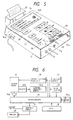
- This indicator device 14 comprises a LED display device 14a, a buzzer 14b and etc., as shown in Figs. 5 and 6.
- the powder brake 10 Since the powder brake 10 has a constant-torque and low-inertia load function, it is capable of providing accurate data, which is proportional to the physical strength (i.e., foot pressing force) of the subject. For this reason, the powder brake of the present invention is used as the load device.
- the slide rail 4 comprises right and left horizontal slide rails 4a and 4a (Fig. 1), and an inclined slide rail 4b disposed centrally and slanted upwardly in a forward direction.
- a guide roller 5b mounted on a lower end of a bracket 5a mounted on the reverse face of the foot plate 5 is received in the inclined slide rail 4b, so that the upstanding angle of the foot plate 5 slidable along the slide rail 4 in forward and backward directions can be varied.
- Handles 31 are also provided for the subject M to grasp for stabilizing his sitting posture.
- the transmitting device 9 which transmits the rotation of the drum 7 to the powder brake 10, comprises a sprocket 9a mounted on a rotation shaft 7a of the drum 7 and a free wheel 9c rotated in one direction by a chain 9b extending around the sprocket 9a.
- Transmitting device 9 also includes a sprocket 9d mounted on a rotation shaft of free wheel 9c, and a sprocket 9f rotated by a chain 9e extended around the sprocket 9d.
- the rotation shaft of the sprocket 9f also serves as an output shaft of the powder brake 10.
- the LED display device 14a and the buzzer 14b which visually and auditorially indicate the average speed (m/sec), the average foot- pressing force (kg), the average power (W) and the peak power (W), are mounted on a control panel 15 mounted on the front end of the slide rail 4.
- Rotation frequency pulse from an encoder 12b disposed on an axis of the powder brake 10 are fed via the rotation frequency sensor 12a to a pulse counter 16 (Fig. 6), which counts the input pulses at sampling intervals and feeds the microcomputer 13 digital data corresponding to the speed with which the foot plate 5 moves.
- Figs. 5 and 6 data from switches 17a and 17b, are also transmitted to the microcomputer 13, from which predetermined processing is carried out based on the power theory, so that the average speed (m/sec) such as a horizontal component of an instant speed of the foot plate 5 when the subject brings his legs into an extended position is averaged by the time of period from a bent position to the extended position in his legs, the average foot-pressing force (kg) such as an instant foot pressing force of an output of the load sensor 11 is averaged in the same manner described above, the average power (W) which is averaged in the same manner described above, the peak power (W), etc., are displayed on the indicator device 14.
- m/sec such as a horizontal component of an instant speed of the foot plate 5 when the subject brings his legs into an extended position
- the microcomputer 13 feeds a predetermined current to the powder brake 10 via a constant voltage power unit 18 in accordance with a curve for current-torque having a load characteristic which has been measured in order to apply a force of a predetermined weight decided by key operation to the foot plate 5.
- the various data of the microcomputer 13 are supplied to a host computer (not shown via an interface circuit 19, which manages the measurement results.
- reference numeral 20 denotes a timer indicator
- reference numeral 21 an input switch
- reference numeral 22 a start switch
- reference numeral 23 a reset switch
- reference numeral 24 a ready switch
- reference numeral 25 a printer
- reference numeral 26 a ten-key.
- the various data of the subject M are inputted by these switches so that desired parameters can be set.
Abstract
Description
- This invention relates to an apparatus used for measuring the physical strength of a person. More specifically, the invention relates to an apparatus which dynamically measures the instantaneous power output of a single leg muscle, via the leg extending power of the subject. The present invention also monitors forms of motion by measuring the instantaneous power of a multi-articular motion such as a vertical jump.
- The following problems have been noted with respect to conventional physical strength tests such as a vertical jump test, a reciprocal jump test and a dorsal muscle test.
- (1) It is difficult to link the test results with a synthetic appraisal, since various functions are appraised separately.
- (2) Appraisal standards are ambiguous. For example, with respect to a vertical jump, the appraisal standard is the height to which one can jump; however, this is an index of the performance, and is an indirect and substitutive appraisal of the physical strength.
- (3) There is no standardized scientific proof, which relates an index of performance (i.e. a persons vertical jump to physical strength.
- (4) Often the test subject must perform unusual movements with a large load, which often result in injury. Recently, an increased interest in physical strength has generated a demand for a method and apparatus, which measures physical strength easily, safely and accurately. Also, a study has been made, which creates an index of the physical strength based on the power theory.
- In the power theory, physical strength is measured as the capacity of the energy (integrating value of the power), or the power is measured as an index. Forms of power development are classified according to energy developing mechanisms (i.e. specific muscles) in a living body. Within each form of development, the upper limit value of power is measured while monitoring the corresponding energy developing mechanism (muscle). This measured upper limit is used as an index of physical strength in the corresponding energy developing mechanism.
- Specifically, the measurements are carried out in the following manner:
- Duration: Infinite
Appraisal of upper limit power: Power available at 75% of the maximum heat rate, etc. - Main factor for energy generation: Oxygen
- Duration: About 30 seconds
Appraisal of upper limit power: Average power, critical power, etc. - Main factor for energy generation: Glycogen
- Duration: About 7 seconds
Appraisal of upper limit power: The optimum value determined by speed and developing force of the peak power around approximately 5 to 6 seconds. - Main factor for energy generation: ATP-CP type chemical energy.
- In connection with the above energy mechanisms (a) and (c), a measurement apparatus utilizing a bicycle ergometer has been proposed by the Applicant of the present invention (Japanese Patent Publication No. 42694/89), and there are known "AEROBIKE" and "POWERMAX" (both of which are registered and pending trademarks of Konbi Corporation; the former is Japanese Trademark Registration No. 1840771, and the latter is Japanese Trademark Publication No. 42348/86) to which the above techniques are applied.
- The energy mechanism of example (b) can be carried out with a Wingate test. An apparatus for measuring an instantaneous power of the subject utilizes a bicycle ergometer, since the pedaling motion is analogous to a usual running motion and is rhythmic. The power can be produced efficiently, with less injuries resulting.
- On the other hand, with respect to a continuous leg muscle power exercise or other similar multi-articular exercise, the instantaneous power of a single leg muscle is also an important factor, for example, when hastily avoiding an obstacle in daily life. An apparatus is known, which measures the instantaneous power of a single development leg muscle, for example, as disclosed in Japanese Laid-Open (Kokai) Utility Model a Application No. 18103/88. In this application, a leg's extension power is received by a hydraulic or pneumatic cylinder, and the physical strength of the subject is measured according to data from the cylinder.
- However, in the above leg extension measuring apparatus, the adjustment of the cylinder is very difficult. In addition, since the load varies in accordance with the speed, it is difficult to accurately measure the instantaneous power.
- Further, when using the hydraulic cylinder, the response time of the hydraulic pressure is slow, which prevents an accurate measurement.
- From EP-A-0 267 071 a training device is known which includes a drive unit for braking the movement of a rope when the rope is pulled out of the drive unit.
- From NL-A-8 203 228 an apparatus for measuring the leg muscle force is known. The apparatus comprises a seat on which a subject is seated, a slide rail extending forwardly and a foot plate. The foot plate is kept immovable.
- The present invention, which has been made to solve the foregoing problems, has as its object the accurate measurement (based upon a power theory) of an instantaneous power, while eliminating unstable factors of the measuring system as much as possible.
- According to the present invention this object is solved by an apparatus for measuring an instantaneous power generated during a leg extending motion, said apparatus comprising:
a seat on which a subject is seated;
a slide rail extending forwardly;
a foot plate;
characterized in that said seat is provided above a drive system unit; said slide rail extending forwardly from the drive system unit; said foot plate being slidably connected to the slide rail, wherein said foot plate slides in a forward direction in response to a leg extension motion of said subject; and by
a rope provided in the drive system unit, said rope being connected to said foot plate and being paid out of said drive system unit in response to the forward sliding movement of the foot plate;
a transmission device rotated by said rope, as said rope is paid out of said drive system unit;
a powder brake rotated by the transmission device;
foot load sensor means, mounted on the foot plate, for detecting a foot load developed during operation of the apparatus;
rotation frequency sensor means, provided within the drive system unit, for detecting a rotation frequency of the powder brake;
processing means for calculating an average speed, an average muscle power, an average power and a peak power generated during a leg extension operation performed by said subject, wherein said processing means performs said calculations in accordance with detection signals from said foot load sensor means and said rotation frequency sensor means; and
indicator means for indicating processing data calculated by said processing means. - According to the invention an apparatus for measuring the instantaneous power of a leg extension muscle is provided, in which a powder brake is used in order to reduce the influence of the inertia on the power measurement. In addition, as compared with the conventional power measurement based on the non-lactic acid-type anoxia energy mechanism, the present invention shortens the time required to push a foot plate, thereby reducing the burden of the measurement on the subject.
- In the apparatus for measuring an instantaneous power of a leg exending muscle, the device used to produce the load is not hydraulic or of a dynamo type but a power brake having a characteristic to which a torque of the powder brake does not depend upon the roation frequency thereof, since the magnitude of the load produced by these devices varies with the foot-pressing speed. Instead, the present invention produces a load with a constant torque to which an amount of the constant torque is regarded as a weight of a subject corresponding to a brake force of foot plate in consideration of the subject maintaining the weight thereof by legs of the subject, independent of the foot-pressing speed, thereby stabilizing the measurement.
- Embodiments of the present invention are given in the dependent claims. In an apparatus for measuring an instantaneous power of a leg extending muscle the angle of the foot plate is automatically varied in accordance with the amount of leg extension. Previously, the angle of the foot plate was fixed, which caused the foot-pressing force to be unstable because of a change in the angle of inclination of the foot sole during the leg extension.
- Within the present invention, the powder brake is used as the constant-torque low-inertia load mechanism, and the instantaneous power is measured by kicking the foot plate with the subject's full power for a very short time. Therefore, because of the kicking which is a natural form of exercise, the physical burden on the subject is lessened, the measurement of the leg extension of the subject is easier, and the accuracy of the instantaneous power measurement is higher. With respect to forms of motion, because of the above full power kicking, the instantaneous power of the dynamic single-developing multi-articular motion, such as a vertical jump, can be measured.
-
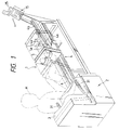
- Fig. 1 is a perspective view of the overall construction of an apparatus for measuring the instantaneous power of a leg extension muscle, provided in accordance with the present invention;
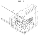
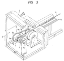
- Figs. 2 and 3 are perspective views of important portions within a drive unit, respectively;
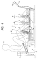
- Fig. 4 is a side-elevational view of the overall construction;
- Fig. 5 is a perspective view of a control panel; and
- Fig. 6 is a block diagram of a control portion including a processing unit.
- One example of an apparatus for measuring the instantaneous power of a leg extension, constituting a preferred embodiment of the present invention, will now be described with reference to the drawings.
- In the drawings, the overall construction of the apparatus for measuring an instantaneous power of a leg extension is designated by reference numeral 1. The apparatus 1 comprises a
seat 3 provided above adrive system unit 2 on which the subject M is to be seated. Aslide rail 4 extends forwardly from thedrive system unit 2 and afoot plate 5 slides along theslide rail 4 in forward and backward directions. The angle of inclination of thefoot plate 5 is variable in accordance with a variation of the angle of the foot sole of the subject M caused by the extension of the subject's legs. Adrum 7 mounted within thedrive system unit 2 has arope 6 wound therearound, which is paid out in response to the forward sliding movement of thefoot plate 5. Areturn spring 8 is mounted on the side of thedrum 7 in order to rewind the paid-outrope 6 on thedrum 7. Thereturn spring 8 is in the form of a cylindrical spring as shown in the drawings. Atransmission device 9 is used to rotate of thedrum 7 and thepowder brake 10 in one direction. Afoot load sensor 11 is mounted on thefoot plate 5 in order to detect the foot load developed (force) when the subject M extends his/her legs. - The present invention also includes a
rotation frequency sensor 12a, provided on the side of thepowder brake 10 as shown in Fig. 2, to detect the rotation frequency of thepowder brake 10. Therotation frequency sensor 12a andfoot load sensor 11 are connected to aprocessing unit 13, which calculates (based upon the power theory) the average speed (m/sec), the average foot-pressing force (kg), the average power (W) and the peak power (W) at the time the subject M extends his/her legs. Anindicator device 14 visually and auditorially indicates data processed by the processing unit 13 (hereinafter referred to as "microcomputer"). Thisindicator device 14 comprises aLED display device 14a, abuzzer 14b and etc., as shown in Figs. 5 and 6. - Since the
powder brake 10 has a constant-torque and low-inertia load function, it is capable of providing accurate data, which is proportional to the physical strength (i.e., foot pressing force) of the subject. For this reason, the powder brake of the present invention is used as the load device. - The
slide rail 4 comprises right and left horizontal slide rails 4a and 4a (Fig. 1), and aninclined slide rail 4b disposed centrally and slanted upwardly in a forward direction. Aguide roller 5b mounted on a lower end of abracket 5a mounted on the reverse face of thefoot plate 5 is received in theinclined slide rail 4b, so that the upstanding angle of thefoot plate 5 slidable along theslide rail 4 in forward and backward directions can be varied.Handles 31 are also provided for the subject M to grasp for stabilizing his sitting posture. - As shown in Figs. 2 and 3, the transmitting
device 9, which transmits the rotation of thedrum 7 to thepowder brake 10, comprises asprocket 9a mounted on arotation shaft 7a of thedrum 7 and a free wheel 9c rotated in one direction by achain 9b extending around thesprocket 9a. Transmittingdevice 9 also includes a sprocket 9d mounted on a rotation shaft of free wheel 9c, and asprocket 9f rotated by achain 9e extended around the sprocket 9d. The rotation shaft of thesprocket 9f also serves as an output shaft of thepowder brake 10. - As shown in Figs. 1 and 5, the
LED display device 14a and thebuzzer 14b, which visually and auditorially indicate the average speed (m/sec), the average foot- pressing force (kg), the average power (W) and the peak power (W), are mounted on acontrol panel 15 mounted on the front end of theslide rail 4. Rotation frequency pulse from anencoder 12b disposed on an axis of thepowder brake 10 are fed via therotation frequency sensor 12a to a pulse counter 16 (Fig. 6), which counts the input pulses at sampling intervals and feeds themicrocomputer 13 digital data corresponding to the speed with which thefoot plate 5 moves. - As shown in Figs. 5 and 6, data from
switches microcomputer 13, from which predetermined processing is carried out based on the power theory, so that the average speed (m/sec) such as a horizontal component of an instant speed of thefoot plate 5 when the subject brings his legs into an extended position is averaged by the time of period from a bent position to the extended position in his legs, the average foot-pressing force (kg) such as an instant foot pressing force of an output of theload sensor 11 is averaged in the same manner described above, the average power (W) which is averaged in the same manner described above, the peak power (W), etc., are displayed on theindicator device 14. Also, themicrocomputer 13 feeds a predetermined current to thepowder brake 10 via a constantvoltage power unit 18 in accordance with a curve for current-torque having a load characteristic which has been measured in order to apply a force of a predetermined weight decided by key operation to thefoot plate 5. The various data of themicrocomputer 13 are supplied to a host computer (not shown via aninterface circuit 19, which manages the measurement results. - In Fig. 5,
reference numeral 20 denotes a timer indicator,reference numeral 21 an input switch, reference numeral 22 a start switch, reference numeral 23 a reset switch, reference numeral 24 a ready switch, reference numeral 25 a printer, and reference numeral 26 a ten-key. The various data of the subject M are inputted by these switches so that desired parameters can be set. - The manner of use and the operation of the above apparatus for measuring an instantaneous power of a leg extension operation, provided in accordance with the present invention, will now be described in detail.
- (1) First, in view of his physical strength, his exercise experience and etc., the subject M, before sitting on the
seat 3, inputs parameters (i.e., his weight and so on) necessary for the measurement through the switches on thecontrol panel 15. - (2) Then, the subject M properly sits on the
seat 3, and moves thefoot plate 5, extending upwardly above theslide rail 4, toward him. The subject M bends his legs and places his feet on thefoot plate 5, with his hands firmly grasping the right and left handles 31. When thebuzzer 14b produces sound, the subject vigorously kicks with his legs in a forward direction so as to push thefoot plate 5 toward the front side of theslide rail 4. As a result of the kicking of thefoot plate 5, therope 6 connected to thefoot plate 5 is vigorously paid out, so that thedrum 7 is rotated against the bias of thereturn spring 8. The rotation of thedrum 7 is transmitted to thepowder brake 10 via thetransmission device 9, that is, via thesprocket 9a, thechain 9b, the free wheel 9c, the sprocket 9d, thechain 9e and thesprocket 9f. - (3) By the above procedure, the first kicking of the
foot plate 5 is completed. - (4) Next, when the subject M brings his extended legs into the initial bent position, the paid out
rope 6 is rewound on thedrum 7 under the bias of thereturn spring 8, so that thefoot plate 5 is automatically returned to the original position, thereby preventing undesired loosening of therope 6. - (5) Subsequently, the above kicking motion is repeated a predetermined number of times within a predetermined time period.
- (6) The foot-pressing load applied by the extended legs during the above kicking motion is accurately detected by the
foot load sensor 11. Also, the rotation of thepowder brake 10 is accurately detected by therotation frequency sensor 12. These detection signals are inputted into themicrocomputer 13, and based on the power theory, themicrocomputer 13 measures the average speed (m/sec), the average foot-pressing force (kg), the average power (W) and the peak power W) at the time of the subject M extends his/her legs. This data is displayed on theLED display device 14a provided on thecontrol panel 15, and outputted from theprinter 25. - (7) The above kicking exercise is terminated when the
buzzer 14b indicates that the predetermined time period is over.
As described in detail above, the powder brake is used as the constant-torque low-inertia load mechanism, and the instantaneous power is measured through the kicking of the foot plate with the subject's full power for a very short time. - Therefore, because of the kicking which is a natural form of exercise, a physical burden on the subject is less, the leg measurement is easy, and the measurement accuracy is high. With respect to forms of motion, because of the above full power kicking, the instantaneous power of the dynamic single-developing multi- articular motion such as a vertical jump can be measured, and other various advantages are achieved.
Claims (7)
- An apparatus for measuring an instantaneous power generated during a leg extending motion, said apparatus comprising:
a seat (3) on which a subject (41) is seated;
a slide rail (4) extending forwardly;
a foot plate (5);
characterized in that said seat (3) is provided above a drive system unit (2); said slide rail (4) extending forwardly from the drive system unit (2); said foot plate (5) being slidably connected to the slide rail, wherein said foot plate slides in a forward direction in response to a leg extension motion of said subject; and by
a rope (6) provided in the drive system unit (2), said rope (6) being connected to said foot plate (5) and being paid out of said drive system unit (2) in response to the forward sliding movement of the foot plate (5);
a transmission device (9) rotated by said rope (6), as said rope is paid out of said drive system unit (2);
a powder brake (10) rotated by the transmission device (9);
foot load sensor means (11), mounted on the foot plate (5), for detecting a foot load developed during operation of the apparatus;
rotation frequency sensor means (12a), provided within the drive system unit (2), for detecting a rotation frequency of the powder brake (10);
processing means (13) for calculating an average speed, an average foot-pressing force, an average power and a peak power generated during a leg extension operation performed by said subject, wherein said processing means (13) performs said calculations in accordance with detection signals from said foot load sensor means (11) and said rotation frequency sensor means (12a); and
indicator means (14) for indicating processing data calculated by said processing means. - The apparatus of claim 1, characterized by said rope (6) being wound upon a drum (7) such that said drum (7) rotates while said rope (6) is paid out in response to the sliding movement of the foot plate (5), the rotation of said drum (7) being transmitted to the transmission device (9).
- The apparatus of claim 2, wherein the rope (6) is rewound upon said drum (7) by a return spring (8).
- The apparatus of any one of claims 1 to 3, wherein an angle of inclination (α) of the foot plate is variable in accordance with variation of an angle of a foot sole of the subject, which is caused in response to the sliding movement of the foot plate.
- The apparatus of claim 4, wherein said slide rail (4) is upwardly inclined in a forward direction such that said slide rail (4) causes said variation in the angle of inclination (α) of said foot plate (5) as the foot plate slides along the slide rail (4).
- The apparatus of claim 1, wherein said powder brake (10) provides a constant-torque and low-inertia load resistance against said foot plate (5), such that said powder brake (10) reduces the inertial influence upon the calculations performed by said processing means.
- The apparatus of claim 6, wherein said processing means (13) transmits a control signal to said powder brake (10) in order to control the load resistance produced by said powder brake (10).
Applications Claiming Priority (2)
| Application Number | Priority Date | Filing Date | Title |
|---|---|---|---|
| JP1304343A JPH03165744A (en) | 1989-11-22 | 1989-11-22 | Instantaneous force measuring device by leg extending force |
| JP304343/89 | 1989-11-22 |
Publications (2)
| Publication Number | Publication Date |
|---|---|
| EP0430067A1 EP0430067A1 (en) | 1991-06-05 |
| EP0430067B1 true EP0430067B1 (en) | 1995-02-01 |
Family
ID=17931870
Family Applications (1)
| Application Number | Title | Priority Date | Filing Date |
|---|---|---|---|
| EP90122302A Expired - Lifetime EP0430067B1 (en) | 1989-11-22 | 1990-11-22 | Apparatus for measuring instantaneous power by leg-stretching power |
Country Status (7)
| Country | Link |
|---|---|
| US (1) | US5260870A (en) |
| EP (1) | EP0430067B1 (en) |
| JP (1) | JPH03165744A (en) |
| AT (1) | ATE117888T1 (en) |
| CA (1) | CA2030502C (en) |
| DE (1) | DE69016607T2 (en) |
| ES (1) | ES2070246T3 (en) |
Cited By (1)
| Publication number | Priority date | Publication date | Assignee | Title |
|---|---|---|---|---|
| CN105193434A (en) * | 2015-09-06 | 2015-12-30 | 河南科技大学第一附属医院 | Lower limb muscle strength measuring instrument |
Families Citing this family (65)
| Publication number | Priority date | Publication date | Assignee | Title |
|---|---|---|---|---|
| US5277674A (en) * | 1991-03-30 | 1994-01-11 | Combi Corporation | Leg extension apparatus with pivotal foot section for measuring instantaneous power generated by a leg extending force |
| DE9115531U1 (en) * | 1991-12-14 | 1992-02-20 | Hammer, Hans-Guenter, 7910 Neu-Ulm, De | |
| AT400223B (en) * | 1993-08-26 | 1995-11-27 | Presl Rudolf | DEVICE FOR DIAGNOSIS AND / OR THERAPY OF A PERSON |
| NL9301956A (en) * | 1993-11-11 | 1995-06-01 | Optische Ind De Oude Delft Nv | Device for converting the force exerted on a support into an electrical signal. |
| US5690594A (en) * | 1995-05-16 | 1997-11-25 | Mankovitz; Roy J. | Exercise apparatus for use with conventional chairs |
| CA2221105C (en) * | 1995-05-16 | 2006-07-18 | Roy J. Mankovitz | Exercise apparatus for use with conventional chairs |
| US5743050A (en) * | 1995-12-01 | 1998-04-28 | Shibata; Tsutomu | Training room serving also as bed room |
| US5634874A (en) * | 1996-02-02 | 1997-06-03 | Anthony M. Kest | Portable upper anatomy exercise device |
| US5762592A (en) * | 1996-08-29 | 1998-06-09 | Neveux; Patrick | Stretch machine for physical therapy |
| DE19652869C1 (en) * | 1996-12-18 | 1998-03-05 | Bavaria Patente & Lizenzen | Knee bend ergometer with counter |
| US6181647B1 (en) | 1997-02-10 | 2001-01-30 | The University Of Tulsa | Vertical jump measuring device |
| US5838638A (en) * | 1997-02-10 | 1998-11-17 | The University Of Tulsa | Portable verticle jump measuring device |
| US6042523A (en) * | 1997-06-06 | 2000-03-28 | Graham; Gary A. | Therapeutic exercise apparatus and method |
| US5951445A (en) * | 1997-10-14 | 1999-09-14 | Vittone; Larry W. | Leg exercise apparatus |
| GB2337333A (en) * | 1998-05-13 | 1999-11-17 | Christopher Miller | Rowing technique monitor using force sensors attached to the footrests of a boat or rowing machine |
| WO2000010648A1 (en) * | 1998-08-21 | 2000-03-02 | Hunter James C | Abdominal/lowback isolation apparatus |
| US6383122B1 (en) | 1999-01-23 | 2002-05-07 | Gary Graham | Method and apparatus for a rebound system and adjustable resistance system |
| US6743158B2 (en) * | 2000-03-01 | 2004-06-01 | Cybex Interational, Inc. | Leg press |
| US7220221B2 (en) | 2000-05-03 | 2007-05-22 | Nautilus, Inc. | Exercise device with body extension mechanism |
| US6904801B1 (en) * | 2002-04-29 | 2005-06-14 | Tony Bridges | Functional capacity evaluation apparatus and method |
| US7004891B2 (en) * | 2003-03-06 | 2006-02-28 | Nautilus Human Performance Systems, Inc. | Inclined leg press weight training machine |
| ES2263306B1 (en) * | 2003-04-09 | 2007-08-01 | Universidade De Vigo | CONTROLLED VARIABLE RESISTANCE SYSTEM. |
| JP3718211B2 (en) * | 2004-01-16 | 2005-11-24 | コナミスポーツライフ株式会社 | measuring device |
| US7455621B1 (en) | 2004-08-12 | 2008-11-25 | Anthony Donald D | Free-weight exercise monitoring and feedback system and method |
| US7172535B2 (en) * | 2004-10-28 | 2007-02-06 | Volmar John F | Upper back exercise machine and method of use |
| EP1714615A1 (en) * | 2005-04-20 | 2006-10-25 | Michael Dr. Schocke | Ergometer suitable for use with magnetic resonance devices |
| US20100197462A1 (en) * | 2005-09-07 | 2010-08-05 | Bvp Holding, Inc. | 3-d, interactive exercise analysis, gaming, and physical therapy system |
| US7871358B2 (en) * | 2005-10-14 | 2011-01-18 | Gary Graham | Height adjustable shuttle treatment table/exercise device method and apparatus |
| WO2007048082A2 (en) * | 2005-10-14 | 2007-04-26 | Contemporary Designs, Co. | Treatment table and exercise device method and apparatus |
| US7762963B2 (en) * | 2005-10-24 | 2010-07-27 | Paul Ewing | Therapeutic device for post-operative knee |
| ITRA20060012A1 (en) * | 2006-02-24 | 2007-08-25 | Technogym Spa | GINNICA MACHINE. |
| US20070202992A1 (en) * | 2006-02-28 | 2007-08-30 | Eric Grasshoff | Programmable adaptable resistance exercise system and method |
| US20070213183A1 (en) * | 2006-03-08 | 2007-09-13 | Menektchiev Alexandre K | Sensor arrays for exercise equipment and methods to operate the same |
| JP4977429B2 (en) * | 2006-10-06 | 2012-07-18 | 大和製衡株式会社 | Lower limb muscle strength evaluation method and lower limb muscle strength evaluation device |
| CA2612426C (en) * | 2006-11-27 | 2016-03-29 | Neil M. Cole | Training system and method |
| DE102008023573A1 (en) * | 2008-05-05 | 2009-11-12 | Medireha GmbH Produkte für die medizinische Rehabilitation | Leg movement splint for repetitive movement of the knee and hip joint with assistance function during active use |
| CN102309332A (en) * | 2010-06-30 | 2012-01-11 | 淄博天燧工贸有限公司 | Athlete lower limb strength load tester |
| US9962574B2 (en) * | 2011-05-10 | 2018-05-08 | Sperry Product Innovation, Inc. | Exercise apparatus |
| US9339691B2 (en) | 2012-01-05 | 2016-05-17 | Icon Health & Fitness, Inc. | System and method for controlling an exercise device |
| US8814764B2 (en) * | 2012-01-23 | 2014-08-26 | Torrey Vaughns | Abdominal exercising apparatus |
| JP5426804B1 (en) * | 2012-07-05 | 2014-02-26 | パナソニック株式会社 | Support device, motion support device, and strength training support device |
| EP3653271A1 (en) * | 2012-11-16 | 2020-05-20 | Hill-Rom Services, Inc. | Person support apparatuses having exercise therapy features |
| EP2969058B1 (en) | 2013-03-14 | 2020-05-13 | Icon Health & Fitness, Inc. | Strength training apparatus with flywheel and related methods |
| EP3974036A1 (en) | 2013-12-26 | 2022-03-30 | iFIT Inc. | Magnetic resistance mechanism in a cable machine |
| WO2015138339A1 (en) | 2014-03-10 | 2015-09-17 | Icon Health & Fitness, Inc. | Pressure sensor to quantify work |
| US9463126B2 (en) | 2014-03-11 | 2016-10-11 | Hill-Rom Services, Inc. | Caregiver universal remote cart for patient bed control |
| WO2015191445A1 (en) | 2014-06-09 | 2015-12-17 | Icon Health & Fitness, Inc. | Cable system incorporated into a treadmill |
| WO2015195965A1 (en) | 2014-06-20 | 2015-12-23 | Icon Health & Fitness, Inc. | Post workout massage device |
| US10391361B2 (en) | 2015-02-27 | 2019-08-27 | Icon Health & Fitness, Inc. | Simulating real-world terrain on an exercise device |
| US10675497B2 (en) | 2015-09-18 | 2020-06-09 | Jaquish Biomedical Corporation | Devices for exercise apparatuses |
| WO2017049198A1 (en) | 2015-09-18 | 2017-03-23 | Jaquish Industrial Research LLC | Devices for exercise apparatuses |
| US10272317B2 (en) | 2016-03-18 | 2019-04-30 | Icon Health & Fitness, Inc. | Lighted pace feature in a treadmill |
| US10625137B2 (en) | 2016-03-18 | 2020-04-21 | Icon Health & Fitness, Inc. | Coordinated displays in an exercise device |
| US10493349B2 (en) | 2016-03-18 | 2019-12-03 | Icon Health & Fitness, Inc. | Display on exercise device |
| US10350127B2 (en) * | 2016-07-04 | 2019-07-16 | Sean Kelly | Unilateral leg press machine |
| IT201600087533A1 (en) * | 2016-08-26 | 2018-02-26 | Dtp Work Group S R L | "PHYSICAL EXERCISE MACHINE" |
| US10671705B2 (en) | 2016-09-28 | 2020-06-02 | Icon Health & Fitness, Inc. | Customizing recipe recommendations |
| KR102463832B1 (en) * | 2018-01-29 | 2022-11-07 | 현대자동차주식회사 | Convenience apparatus for vehicle |
| US11148003B1 (en) | 2018-07-03 | 2021-10-19 | Gary Graham | Range of motion limiting device for shuttle carriage |
| US11383131B2 (en) | 2018-10-11 | 2022-07-12 | Tony Bridges | Functional capacity evaluation systems and methods |
| CA3118771A1 (en) * | 2018-11-28 | 2020-06-04 | Danish Aerospace Company A/S | A multifunctional exercise apparatus |
| CN110327062B (en) * | 2019-04-26 | 2023-12-19 | 四川大学 | Be used for shank muscle dynamometry seat |
| CN112891842A (en) * | 2021-02-26 | 2021-06-04 | 刘敬侠 | Obstetrical department postoperative rehabilitation training device |
| CN113577684B (en) * | 2021-08-12 | 2022-05-17 | 河南中医药大学 | Lower limb rehabilitation training device for children |
| USD989894S1 (en) | 2022-11-08 | 2023-06-20 | Gavin Edward Hamer | Sliding exercise and measurement device |
Family Cites Families (14)
| Publication number | Priority date | Publication date | Assignee | Title |
|---|---|---|---|---|
| US3387493A (en) * | 1965-05-12 | 1968-06-11 | Wallace S. Strittmatter | Motor-operated exercising device with load responsive indicating means |
| US3820782A (en) * | 1971-08-13 | 1974-06-28 | L Salkeld | Leg exercising apparatus |
| US3734495A (en) * | 1971-10-26 | 1973-05-22 | Whittaker Corp | A seat and leg operated load lifting device |
| NL8203228A (en) * | 1982-08-17 | 1984-03-16 | Ronald Christiaan De Buck | Muscle power meter for medical use - uses measuring units mounted in frame to measure force exerted by patients leg, arm, back and abdominal muscles |
| US4550908A (en) * | 1984-01-16 | 1985-11-05 | Dixon Voris F | Physical-rehabilitation and exercising apparatus |
| US4621620A (en) * | 1984-04-16 | 1986-11-11 | Gene Anderson | Human limb manipulation device |
| US4702108A (en) * | 1985-06-24 | 1987-10-27 | Regents Of The Univ. Of Minnesota | Method and apparatus for measuring the isometric muscle strength of multiple muscle groups in the human body |
| US4714244A (en) * | 1986-04-04 | 1987-12-22 | Bally Manufacturing Corporation | Rowing machine with improved mechanical features |
| JPS6346186A (en) * | 1986-08-13 | 1988-02-27 | 美津濃株式会社 | Rowing machine |
| FR2604911B1 (en) * | 1986-10-13 | 1989-06-02 | Merobel | TRAINING, INVESTIGATION AND REHABILITATION APPARATUS, ESPECIALLY OF THE NEURO-MUSCULAR FUNCTION |
| US4786051A (en) * | 1986-10-30 | 1988-11-22 | Mullican Joe E | Exercising apparatus |
| US4765613A (en) * | 1987-01-22 | 1988-08-23 | Paramount Fitness Equipment Corporation | Progressive resistance exercise device |
| JPH089438B2 (en) * | 1989-04-26 | 1996-01-31 | 日本たばこ産業株式会社 | Cutting device for feeding out the leading edge of the band-shaped material fed from the winding roll |
| US5072929A (en) * | 1990-06-13 | 1991-12-17 | Nordictrack, Inc. | Dual resistance exercise rowing machine |
-
1989
- 1989-11-22 JP JP1304343A patent/JPH03165744A/en active Granted
-
1990
- 1990-11-20 US US07/615,960 patent/US5260870A/en not_active Expired - Fee Related
- 1990-11-21 CA CA002030502A patent/CA2030502C/en not_active Expired - Fee Related
- 1990-11-22 DE DE69016607T patent/DE69016607T2/en not_active Expired - Fee Related
- 1990-11-22 AT AT90122302T patent/ATE117888T1/en active
- 1990-11-22 ES ES90122302T patent/ES2070246T3/en not_active Expired - Lifetime
- 1990-11-22 EP EP90122302A patent/EP0430067B1/en not_active Expired - Lifetime
Cited By (1)
| Publication number | Priority date | Publication date | Assignee | Title |
|---|---|---|---|---|
| CN105193434A (en) * | 2015-09-06 | 2015-12-30 | 河南科技大学第一附属医院 | Lower limb muscle strength measuring instrument |
Also Published As
| Publication number | Publication date |
|---|---|
| JPH0515457B2 (en) | 1993-03-01 |
| US5260870A (en) | 1993-11-09 |
| CA2030502C (en) | 1995-07-25 |
| JPH03165744A (en) | 1991-07-17 |
| ATE117888T1 (en) | 1995-02-15 |
| CA2030502A1 (en) | 1991-05-23 |
| DE69016607D1 (en) | 1995-03-16 |
| ES2070246T3 (en) | 1995-06-01 |
| EP0430067A1 (en) | 1991-06-05 |
| DE69016607T2 (en) | 1995-07-06 |
Similar Documents
| Publication | Publication Date | Title |
|---|---|---|
| EP0430067B1 (en) | Apparatus for measuring instantaneous power by leg-stretching power | |
| EP0507051B1 (en) | Apparatus for and method of measuring instantaneous power generated by a leg extending force | |
| US4912638A (en) | Biofeedback lifting monitor | |
| EP0422325B1 (en) | Method of and apparatus for measuring instantaneous power | |
| US4934692A (en) | Exercise apparatus providing resistance variable during operation | |
| US8360935B2 (en) | Method, a computer program, and device for controlling a movable resistance element in a training device | |
| US4848152A (en) | Biofeedback lifting monitor | |
| US4770411A (en) | Exercise apparatus ergometer | |
| WO1992013488A1 (en) | Cycle ergometer | |
| Fregly et al. | Crank inertial load has little effect on steady-state pedaling coordination | |
| Funato et al. | Ergometry for estimation of mechanical power output in sprinting in humans using a newly developed self-driven treadmill | |
| Jaskolski et al. | Optimal resistance for maximal power during treadmill running | |
| JP2533413B2 (en) | Instantaneous force measurement device based on leg extension force | |
| JPH056967Y2 (en) | ||
| JP4713746B2 (en) | Muscle strength measurement method | |
| JP2794265B2 (en) | Competition measurement system | |
| JP3208111B2 (en) | Leg muscle endurance measurement device | |
| JPH05293200A (en) | Measuring method for instantaneous motive force by leg extending force | |
| CN211536330U (en) | Constant-speed muscle strength training equipment | |
| US11964189B2 (en) | Training device with adjustable resistance | |
| JP2003290181A (en) | Myodynamia measuring method and apparatus therefor in cycle type ergometer | |
| JP2974078B2 (en) | Athletic ability measurement and evaluation device | |
| US20220080264A1 (en) | Training device | |
| JPH08138B2 (en) | Rowing ergometer | |
| JP3933630B2 (en) | Exercise therapy equipment |
Legal Events
| Date | Code | Title | Description |
|---|---|---|---|
| PUAI | Public reference made under article 153(3) epc to a published international application that has entered the european phase |
Free format text: ORIGINAL CODE: 0009012 |
|
| AK | Designated contracting states |
Kind code of ref document: A1 Designated state(s): AT BE CH DE DK ES FR GB GR IT LI LU NL SE |
|
| 17P | Request for examination filed |
Effective date: 19910604 |
|
| 17Q | First examination report despatched |
Effective date: 19930820 |
|
| GRAA | (expected) grant |
Free format text: ORIGINAL CODE: 0009210 |
|
| AK | Designated contracting states |
Kind code of ref document: B1 Designated state(s): AT BE CH DE DK ES FR GB GR IT LI LU NL SE |
|
| PG25 | Lapsed in a contracting state [announced via postgrant information from national office to epo] |
Ref country code: NL Effective date: 19950201 Ref country code: LI Effective date: 19950201 Ref country code: GR Free format text: LAPSE BECAUSE OF FAILURE TO SUBMIT A TRANSLATION OF THE DESCRIPTION OR TO PAY THE FEE WITHIN THE PRESCRIBED TIME-LIMIT Effective date: 19950201 Ref country code: DK Effective date: 19950201 Ref country code: CH Effective date: 19950201 Ref country code: BE Effective date: 19950201 Ref country code: AT Effective date: 19950201 |
|
| REF | Corresponds to: |
Ref document number: 117888 Country of ref document: AT Date of ref document: 19950215 Kind code of ref document: T |
|
| ITF | It: translation for a ep patent filed |
Owner name: SOCIETA' ITALIANA BREVETTI S.P.A. |
|
| REF | Corresponds to: |
Ref document number: 69016607 Country of ref document: DE Date of ref document: 19950316 |
|
| ET | Fr: translation filed | ||
| PG25 | Lapsed in a contracting state [announced via postgrant information from national office to epo] |
Ref country code: SE Effective date: 19950501 |
|
| REG | Reference to a national code |
Ref country code: CH Ref legal event code: PL |
|
| REG | Reference to a national code |
Ref country code: ES Ref legal event code: FG2A Ref document number: 2070246 Country of ref document: ES Kind code of ref document: T3 |
|
| NLV1 | Nl: lapsed or annulled due to failure to fulfill the requirements of art. 29p and 29m of the patents act | ||
| PGFP | Annual fee paid to national office [announced via postgrant information from national office to epo] |
Ref country code: GB Payment date: 19951113 Year of fee payment: 6 |
|
| PGFP | Annual fee paid to national office [announced via postgrant information from national office to epo] |
Ref country code: ES Payment date: 19951116 Year of fee payment: 6 |
|
| PGFP | Annual fee paid to national office [announced via postgrant information from national office to epo] |
Ref country code: FR Payment date: 19951129 Year of fee payment: 6 |
|
| PG25 | Lapsed in a contracting state [announced via postgrant information from national office to epo] |
Ref country code: LU Free format text: LAPSE BECAUSE OF NON-PAYMENT OF DUE FEES Effective date: 19951130 |
|
| PGFP | Annual fee paid to national office [announced via postgrant information from national office to epo] |
Ref country code: DE Payment date: 19951207 Year of fee payment: 6 |
|
| PLBE | No opposition filed within time limit |
Free format text: ORIGINAL CODE: 0009261 |
|
| STAA | Information on the status of an ep patent application or granted ep patent |
Free format text: STATUS: NO OPPOSITION FILED WITHIN TIME LIMIT |
|
| 26N | No opposition filed | ||
| PG25 | Lapsed in a contracting state [announced via postgrant information from national office to epo] |
Ref country code: GB Effective date: 19961122 |
|
| PG25 | Lapsed in a contracting state [announced via postgrant information from national office to epo] |
Ref country code: ES Free format text: LAPSE BECAUSE OF NON-PAYMENT OF DUE FEES Effective date: 19961123 |
|
| GBPC | Gb: european patent ceased through non-payment of renewal fee |
Effective date: 19961122 |
|
| PG25 | Lapsed in a contracting state [announced via postgrant information from national office to epo] |
Ref country code: FR Effective date: 19970731 |
|
| PG25 | Lapsed in a contracting state [announced via postgrant information from national office to epo] |
Ref country code: DE Effective date: 19970801 |
|
| REG | Reference to a national code |
Ref country code: FR Ref legal event code: ST |
|
| REG | Reference to a national code |
Ref country code: ES Ref legal event code: FD2A Effective date: 19971213 |
|
| PG25 | Lapsed in a contracting state [announced via postgrant information from national office to epo] |
Ref country code: IT Free format text: LAPSE BECAUSE OF NON-PAYMENT OF DUE FEES;WARNING: LAPSES OF ITALIAN PATENTS WITH EFFECTIVE DATE BEFORE 2007 MAY HAVE OCCURRED AT ANY TIME BEFORE 2007. THE CORRECT EFFECTIVE DATE MAY BE DIFFERENT FROM THE ONE RECORDED. Effective date: 20051122 |