EP0429889A2 - Auxiliary signal transmission in transmission systems for high bit-rate digital signals - Google Patents
Auxiliary signal transmission in transmission systems for high bit-rate digital signals Download PDFInfo
- Publication number
- EP0429889A2 EP0429889A2 EP90121128A EP90121128A EP0429889A2 EP 0429889 A2 EP0429889 A2 EP 0429889A2 EP 90121128 A EP90121128 A EP 90121128A EP 90121128 A EP90121128 A EP 90121128A EP 0429889 A2 EP0429889 A2 EP 0429889A2
- Authority
- EP
- European Patent Office
- Prior art keywords
- bit
- zero
- bits
- binary
- sequence
- Prior art date
- Legal status (The legal status is an assumption and is not a legal conclusion. Google has not performed a legal analysis and makes no representation as to the accuracy of the status listed.)
- Granted
Links
Images
Classifications
-
- H—ELECTRICITY
- H04—ELECTRIC COMMUNICATION TECHNIQUE
- H04L—TRANSMISSION OF DIGITAL INFORMATION, e.g. TELEGRAPHIC COMMUNICATION
- H04L25/00—Baseband systems
- H04L25/38—Synchronous or start-stop systems, e.g. for Baudot code
- H04L25/40—Transmitting circuits; Receiving circuits
- H04L25/49—Transmitting circuits; Receiving circuits using code conversion at the transmitter; using predistortion; using insertion of idle bits for obtaining a desired frequency spectrum; using three or more amplitude levels ; Baseband coding techniques specific to data transmission systems
- H04L25/4906—Transmitting circuits; Receiving circuits using code conversion at the transmitter; using predistortion; using insertion of idle bits for obtaining a desired frequency spectrum; using three or more amplitude levels ; Baseband coding techniques specific to data transmission systems using binary codes
- H04L25/4908—Transmitting circuits; Receiving circuits using code conversion at the transmitter; using predistortion; using insertion of idle bits for obtaining a desired frequency spectrum; using three or more amplitude levels ; Baseband coding techniques specific to data transmission systems using binary codes using mBnB codes
- H04L25/491—Transmitting circuits; Receiving circuits using code conversion at the transmitter; using predistortion; using insertion of idle bits for obtaining a desired frequency spectrum; using three or more amplitude levels ; Baseband coding techniques specific to data transmission systems using binary codes using mBnB codes using 1B2B codes
- H04L25/4912—Transmitting circuits; Receiving circuits using code conversion at the transmitter; using predistortion; using insertion of idle bits for obtaining a desired frequency spectrum; using three or more amplitude levels ; Baseband coding techniques specific to data transmission systems using binary codes using mBnB codes using 1B2B codes using CMI or 2-HDB-3 code
Definitions
- the invention relates to a method for the additional transmission of a digital signal according to the preamble of claim 1.
- a transmission system for digital signals of high walking speed is known, in which a signal of comparatively low walking speed is also transmitted.
- the known transmission system contains code converters in the line terminals which convert the digital signal to be transmitted into the actual transmission code, in particular into a 4B 3T code or a 5B 6B code on the transmission side and reset on the reception side.
- the required clock signal is generated by means of a phase-locked loop and the control voltage of the phase-locked loop is additionally amplitude-modulated to transmit the additional signal and thus phase-modulated the signals delivered to the line via the clock signal.
- phase discriminator contained in the phase-locked loop for clock generation also acts as a demodulator for the additional signals that can be taken from the phase discriminator output.
- the transmission capacity for an additional signal is limited in this prior art, since a phase shift that is too large would produce considerable undesirable jitter, which would then require additional effort for eliminating the jitter or the effects on the useful signal transmission.
- phase modulation is undesirable since it can only be generated with digital modules in rare cases.
- the object of the invention is therefore to develop a method of the type mentioned at the outset in such a way that there is a higher transmission capacity for an additional signal and the process can be implemented with digital and thus easily integrated modules.
- it must be ensured that the transmission of the digital useful signals continues to be error-free, and the reception-side generation of a clock signal from the received transmission signals must continue to be possible with the required accuracy.
- the object is achieved by a method of the type mentioned at the outset, which is further developed by the features of the characterizing part of patent claim 1.
- a particular advantage of the method according to the invention is the possibility of being able to distinguish normal transmission errors from the artificially inserted code rule violations, so that the frequency of errors in the digital useful signal can still be measured at the end of the transmission path.
- Two alternative options for developing the method according to the invention are described in more detail in claims 2 and 3, while in claims 4 to 6 a preferred embodiment of the method according to the invention is described in detail.
- the transmission signals in the CMI code are usually generated from binary signals by transcoding.
- a binary zero character is converted during the encoding into an element combination consisting of a zero bit and a one-bit, while a binary one character during the encoding, if the last binary one character was encoded as a double zero character, into a double one character and, if the last binary one character as a double one character was encoded, converted to a double zero character.
- This assignment or the characters are changed when a one-bit begins in the additional signal to be transmitted. Instead of the start of a one-bit of the additional signal, the start of a zero bit could also be selected, but the start of a one-bit is easier to recognize, so that this variant was preferred in the exemplary embodiment.
- the code rule violation is not restricted to one element combination in the CMI code, but a first prohibited element combination, i.e. the CMI, becomes available when a one bit of the additional signal begins Code rule contradicts, sent out, followed by a first regular element combination and a second prohibited element combination.
- a characteristic double violation of the CMI code which includes a regular element combination.
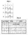
- FIG. 1 in the top line labeled B, a bit sequence consisting of three binary characters is shown, which is to be recoded into the CMI code.
- the line labeled C1 shows the impulses that occur during regular recoding into the CMI code, assuming was that the last recoded binary one bit was reproduced with a double zero bit in the CMI code.
- the element combinations 110100 result in the CMI code, whereby, as can be seen, NRZ signals were assumed, and the pulses in each case fill the entire length of the element in the CMI code, comparable full-bit-wide signals in the binary code.
- Received element combinations are shown in the line labeled C2, the second element being falsified by a transmission error in the first element combination.
- This transmission error is easily recognizable at the receiving end, since binary one bits are only reproduced as double ones or double zero element combinations and a binary zero bit is only represented by a zero-one element combination.
- the zero-one element combination generated by the transmission error is not included in the intended CMI code and can therefore be recognized as a transmission error.
- a double code rule violation to mark the beginning of a one-bit of the additional signal was deliberately shown when the binary string B was recoded.
- the double zero element combination corresponds to the element combination intended for a binary one-bit, because of the assumed history - the last binary one should have been coded as a double zero element combination - the CMI code rule was violated with the first element combination.
- the second element combination corresponds to the CMI code rule, so that there is no code rule violation.
- a double zero element combination was again generated as the third element combination, although the first double zero element combination should have been followed by a double one element combination with regular recoding. It can thus be seen at the receiving end that there is a second code rule violation, that is to say a total of a regular element combination is enclosed by two irregular element combinations.
- FIG. 2 shows a diagram for the additional signal insertion when transcoding binary three-bit words into CMI words consisting of three element combinations.
- the schema results from assigning a clear binary signal content to the element combinations prohibited by the CMI code rule, instead of a single violation of the CMI code rule by performing a double violation in such a way that the occurrence of this double violation: violation of the CMI code rule - Non-violation - violation - so that a pretense of transmission errors is extremely unlikely and that only the beginning of each one bit of the additional channel is marked in the manner described.
- the binary three bit words are each assigned a first and a second CMI code word; the first CMI code word is generated if the last one in the CMI code was reproduced with a double zero bit, accordingly the second CMI word is generated if the immediately preceding last one in the CMI code was reproduced with a double one bit.
- a digital useful signal consisting of a sequence of three binary zero bits results as the first and second CMI word in the same sequence from one one bit, two zero bits, two one bits and one zero bit.
- a binary three-bit word consisting of a sequence of two zero bits and one one-bit is not provided, so that no CMI words have been provided for this.
- a binary three-bit word consisting of a sequence of one zero bit, one one-bit and one zero bit results in a sequence of one one-bit, one zero bit, three one-bit and one zero-bit as the first CMI word and one sequence of one one-bit, three as the second CMI word Zero bit, one bit and one zero bit.
- a binary three-bit word consisting of a sequence of one zero bit and two one bits results in a sequence of one one bit, one zero bit and four one bits as the first CMI word and one sequence as the second CMI word from one bit and five zero bits.
- a binary three-bit word consisting of a sequence of one bit and two zero bits results in a sequence of three zero bits, two one bits and one zero bit as the first CMI word and a sequence of two one bits, one zero bit, two one bits and as the second CMI word a zero bit.
- a binary three-bit word consisting of a sequence of one bit, one zero bit and one one bit results in a sequence of three zero bits, one one bit and two zero bits as the first CMI word and a sequence of two one bits, one zero bit and as the second CMI word three one bits.
- a binary three-bit word consisting of a sequence of two one-bit and one zero bit results in a sequence of two zero bits, three one-bit and one zero bit as the first CMI word and a sequence of two one-bit, two zero bit, one one bit and as the second CMI word a zero bit and a binary three-bit word consisting of three one bits results in a sequence of two zero bits and four one bits as the first CMI word and a sequence of two one bits and four zero bits as the second CMI word. If the binary three-bit word consisting of a sequence of two zero bits and one one-bit is present, the beginning of a one-bit of the additional signal is not shown immediately, but only with the next bit of the digital useful signal.
- the then existing three-bit word begins with the permitted combination of zero and one and thus enables the additional signal to be faded in in the manner described.
- the reason for the non-use of the binary three-bit word consisting of two zeros and a one for the overlay is that the application of the special violation rule described leads to the formation of CMI code elements, which also result from a single transmission error from a regular CMI Signal can arise.
Landscapes
- Physics & Mathematics (AREA)
- Spectroscopy & Molecular Physics (AREA)
- Engineering & Computer Science (AREA)
- Computer Networks & Wireless Communication (AREA)
- Signal Processing (AREA)
- Dc Digital Transmission (AREA)
- Digital Transmission Methods That Use Modulated Carrier Waves (AREA)
- Reduction Or Emphasis Of Bandwidth Of Signals (AREA)
- Synchronisation In Digital Transmission Systems (AREA)
- Time-Division Multiplex Systems (AREA)
Abstract
Description
Die Erfindung betrifft ein Verfahren zur zusätzlichen Übertragung eines digitalen Signals entsprechend dem Oberbegriffs des Anspruchs 1.The invention relates to a method for the additional transmission of a digital signal according to the preamble of
Aus der DE-A1-33 30 683 ist ein Übertragungssystem für digitale Signale hoher Schrittgeschwindigkeit bekannt, bei dem zusätzlich ein Signal vergleichsweise niedriger Schrittgeschwindigkeit mitübertragen wird. Das bekannte Übertragungssystem enthält in den Leitungsendgeräten Codeumsetzer, die das zu übertragende digitale Signal in den eigentlichen Übertragungscode, insbesondere in einen 4B 3T-Code oder einen 5B 6B-Code sendeseitig umsetzen und empfangsseitig rückumsetzen. Im sendeseitigen Codeumsetzer wird das benötigte Taktsignal mittels einer Phasenregelschleife erzeugt und zur Übertragung des Zusatzsignals die Regelspannung der Phasenregelschleife zusätzlich amplitudenmoduliert und damit über das Taktsignal die an die Strecke abgegebenen Signale phasenmoduliert. Empfangsseitig wirkt der in der Phasenregelschleife für die Takterzeugung enthaltene Phasendiskriminator auch als Demodulator für die Zusatzsignale, die am Phasendiskriminatorausgang entnehmbar sind. Die Übertragungskapazität für ein Zusatzsignal ist bei diesem Stand der Technik beschränkt, da ein zu großer Phasenhub einen erheblichen unerwünschten Jitter erzeugen würde, der dann einen zusätzlichen Aufwand für die Beseitigung des Jitters bzw. der Auswirkungen auf die Nutzsignalübertragung erfordern würde. Im Hinblick auf eine leichte Integrierbarkeit ist eine Phasenmodulation unerwünscht, da diese nur in seltenen Fällen mit digitalen Bausteinen erzeugt werden kann.From DE-A1-33 30 683 a transmission system for digital signals of high walking speed is known, in which a signal of comparatively low walking speed is also transmitted. The known transmission system contains code converters in the line terminals which convert the digital signal to be transmitted into the actual transmission code, in particular into a 4B 3T code or a 5B 6B code on the transmission side and reset on the reception side. In the transmitter-side code converter, the required clock signal is generated by means of a phase-locked loop and the control voltage of the phase-locked loop is additionally amplitude-modulated to transmit the additional signal and thus phase-modulated the signals delivered to the line via the clock signal. On the reception side, the phase discriminator contained in the phase-locked loop for clock generation also acts as a demodulator for the additional signals that can be taken from the phase discriminator output. The transmission capacity for an additional signal is limited in this prior art, since a phase shift that is too large would produce considerable undesirable jitter, which would then require additional effort for eliminating the jitter or the effects on the useful signal transmission. With regard to ease of integration, phase modulation is undesirable since it can only be generated with digital modules in rare cases.
Die Aufgabe der Erfindung besteht also darin, ein Verfahren der eingangs erwähnten Art so weiterzubilden, daß sich eine höhere Übertragungskapazität für ein Zusatzsignal ergibt und das Verfahren mit digitalen und damit leicht integrierbaren Bausteinen realisiert werden kann. Zusätzlich ist sicherzustellen, daß die Übertragung der digitalen Nutzsignale weiterhin fehlerfrei erfolgt, außerdem muß die empfangsseitige Er zeugung eines Taktsignals aus den empfangenen Übertragungssignalen weiterhin mit der benötigten Genauigkeit möglich sein.The object of the invention is therefore to develop a method of the type mentioned at the outset in such a way that there is a higher transmission capacity for an additional signal and the process can be implemented with digital and thus easily integrated modules. In addition, it must be ensured that the transmission of the digital useful signals continues to be error-free, and the reception-side generation of a clock signal from the received transmission signals must continue to be possible with the required accuracy.
Erfindungsgemäß wird die Aufgabe durch ein Verfahren der eingangs erwähnten Art gelöst, das durch die Merkmale des Kennzeichens des Patentanspruchs 1 weitergebildet ist. Von besonderem Vorteil beim erfindungsgemäßen Verfahren ist die Möglichkeit, normale Übertragungsfehler von den künstlich eingefügten Coderegelverletzungen unterscheiden zu können, so daß auch weiterhin die Fehlerhäufigkeit im digitalen Nutzsignal am Ende der Übertragungsstrecke gemessen werden kann. Zwei alternative Möglichkeiten zur Weiterbildung des erfindungsgemäßen Verfahrens sind in den Patentansprüchen 2 und 3 näher beschrieben, während in den Patentansprüchen 4 bis 6 eine bevorzugte Ausbildung des erfindungsgemäßen Verfahrens detailliert beschrieben ist. Bei diesen Aus- und Weiterbildungen des erfindungsgemäßen Verfahrens ergibt sich als besonderer Vorteil, daß die spektralen Eigenschaften des verwendeten CMI-Codes, also insbesondere Gleichstromfreiheit und hohe Taktinformation, durch die Zusatzsignalübertragung nicht wesentlich verschlechtert werden.According to the invention, the object is achieved by a method of the type mentioned at the outset, which is further developed by the features of the characterizing part of
Die Erfindung soll im folgenden anhand eines Ausführungsbeispiels und mit Hilfe einer Zeichnung näher erläutert werden. Dabei zeigt
- Fig. 1 ein Beispiel für eine Einblendung eines Zusatzbits in die Übertragung der digitalen Nutzsignale und
- Fig. 2 ein Schema für die Zusatzsignaleinblendung bei der Umcodierung der digitalen Nutzsignale von einem 3Bit-Binärcode in den CMI-Code.
- Fig. 1 shows an example of a superposition of an additional bit in the transmission of the digital useful signals and
- Fig. 2 is a diagram for the additional signal insertion when transcoding the digital useful signals from a 3-bit binary code into the CMI code.
Die im CMI-Code vorliegenden Übertragungssignale werden in der Regel aus binären Signalen durch Umcodierung erzeugt. Dabei wird ein binäres Nullzeichen bei der Umcodierung in eine aus einem Nullbit und einem Einsbit bestehende Elementkombination umgeformt, während ein binäres Einszeichen bei der Umcodierung, sofern das letzte binäre Einszeichen als Doppelnullzeichen codiert wurde, zu einem Doppeleinszeichen und, falls das letzte binäre Einszeichen als Doppeleinszeichen codiert wurde, zu einem Doppelnullzeichen umgeformt. Diese Zuordnung bzw. die Zeichen werden verändert, wenn im mit zu übertragenden Zusatzsignal ein Einsbit beginnt. Anstelle des Beginns eines Einsbits des Zusatzsignals könnte auch der Beginn eines Nullbit gewählt werden, der Beginn eines Einsbits ist aber leichter erkennbar, so daß beim Ausführungsbeispiel diese Variante bevorzugt wurde. Zur Sicherheit gegen die Verwechslung von durch Übertragungsfehler verursachten Coderegelverletzungen von den zur Zusatzsignalübertragung erzeugten absichtlichen Coderegelverletzungen wird entsprechend der Erfindung die Coderegelverletzung nicht auf eine Elementkombination im CMI-Code beschränkt, sondern mit Beginn eines Einsbits des Zusatzsignals wird eine erste verbotene Elementkombination, die also der CMI-Coderegel widerspricht, ausgesendet, auf die eine erste reguläre Elementkombination und eine zweite verbotene Elementkombination folgen. Damit ergibt sich eine charakteristische Doppelverletzung des CMI-Codes, die eine reguläre Elementkombination einschließt. Eine derartige Veränderung des CMI-Übertragungssignals ist durch einen einzigen Übertragungsfehler nicht und durch mehrere Übertragungsfehler nur schwer vorzutäuschen, so daß damit absichtliche Coderegelverletzungen von durch Übertragungsfehlern entstandene Coderegelverletzungen empfangsseitig leicht erkannt und damit getrennt werden können.The transmission signals in the CMI code are usually generated from binary signals by transcoding. A binary zero character is converted during the encoding into an element combination consisting of a zero bit and a one-bit, while a binary one character during the encoding, if the last binary one character was encoded as a double zero character, into a double one character and, if the last binary one character as a double one character was encoded, converted to a double zero character. This assignment or the characters are changed when a one-bit begins in the additional signal to be transmitted. Instead of the start of a one-bit of the additional signal, the start of a zero bit could also be selected, but the start of a one-bit is easier to recognize, so that this variant was preferred in the exemplary embodiment. To ensure that code rule violations caused by transmission errors are not confused with the deliberate code rule violations generated for the additional signal transmission, the code rule violation is not restricted to one element combination in the CMI code, but a first prohibited element combination, i.e. the CMI, becomes available when a one bit of the additional signal begins Code rule contradicts, sent out, followed by a first regular element combination and a second prohibited element combination. This results in a characteristic double violation of the CMI code, which includes a regular element combination. Such a change in the CMI transmission signal cannot be simulated by a single transmission error and can only be pretended with difficulty by several transmission errors, so that deliberate code rule violations of code rule violations caused by transmission errors can be easily recognized and thus separated at the receiving end.
In der Figur 1 ist in der mit B bezeichneten obersten Zeile eine aus drei Binärzeichen bestehende Bitfolge dargestellt, die in den CMI-Code umzucodieren ist. In der mit C1 bezeichneten Zeile sind die bei einer regulären Umcodierung in den CMI-Code auftretenden Impulse dargestellt, wobei angenommen wurde, daß das letzte umcodierte binäre Einsbit mit einem Doppelnullbit im CMI-Code wiedergegeben wurde. Im CMI-Code ergeben sich die Elementkombinationen 110100, wobei wie erkennbar - von NRZ-Signalen ausgegangen wurde, und die Impulse jeweils die gesamte Länge des Elements im CMI-Code - vergleichbar vollbitbreiten Signalen im Binärcodeausfüllen. In der mit C2 bezeichneten Zeile sind empfangene Elementkombinationen dargestellt, wobei in der ersten Elementkombination das zweite Element durch einen Übertragungsfehler verfälscht wurde. Dieser Übertragungsfehler ist empfangsseitig leicht erkennbar, da binäre Einsbits nur als Doppeleins bzw. Doppelnull-Elementkombinationen und ein binäres Nullbit nur durch eine Null-Eins-Elementkombination wiedergegeben wird. Die durch den Übertragungsfehler erzeugte Null-Eins-Elementkombination ist im vorgesehenen CMI-Code nicht enthalten, und damit als Übertragungsfehler zu erkennen. In der C3 bezeichneten Zeile ist bei der Umcodierung der Binärzeichenfolge B absichtlich eine doppelte Coderegelverletzung zur Markierung des Beginns eines Einsbits des Zusatzsignals eingeblendet worden. Die Doppelnull-Elementkombination entspricht zwar in der CMI-Coderegel der vorgesehenen Elementkombination für ein binäres Einsbit, wegen der angenommenen Vorgeschichte - die letzte binäre Eins sollte als Doppelnull-Elementkombination codiert worden sein - wurde aber mit der ersten Elementkombination die CMI-Coderegel verletzt. Die zweite Elementkombination entspricht der CMI-Coderegel, so daß bei dieser keine Coderegelverletzung vorliegt. Als dritte Elementkombination wurde wieder eine Doppelnull-Elementkombination erzeugt, obwohl auf die erste Doppelnull-Elementkombination eine Doppeleins-Elementkombination bei regulärer Umcodierung hätte folgen müssen. Damit ist empfangsseitig erkennbar, daß eine zweite Coderegelverletzung vorliegt, daß also insgesamt eine reguläre Elementkombination von zwei irregulären Elementkombinationen eingeschlossen wird.In FIG. 1, in the top line labeled B, a bit sequence consisting of three binary characters is shown, which is to be recoded into the CMI code. The line labeled C1 shows the impulses that occur during regular recoding into the CMI code, assuming was that the last recoded binary one bit was reproduced with a double zero bit in the CMI code. The element combinations 110100 result in the CMI code, whereby, as can be seen, NRZ signals were assumed, and the pulses in each case fill the entire length of the element in the CMI code, comparable full-bit-wide signals in the binary code. Received element combinations are shown in the line labeled C2, the second element being falsified by a transmission error in the first element combination. This transmission error is easily recognizable at the receiving end, since binary one bits are only reproduced as double ones or double zero element combinations and a binary zero bit is only represented by a zero-one element combination. The zero-one element combination generated by the transmission error is not included in the intended CMI code and can therefore be recognized as a transmission error. In the line labeled C3, a double code rule violation to mark the beginning of a one-bit of the additional signal was deliberately shown when the binary string B was recoded. In the CMI code rule, the double zero element combination corresponds to the element combination intended for a binary one-bit, because of the assumed history - the last binary one should have been coded as a double zero element combination - the CMI code rule was violated with the first element combination. The second element combination corresponds to the CMI code rule, so that there is no code rule violation. A double zero element combination was again generated as the third element combination, although the first double zero element combination should have been followed by a double one element combination with regular recoding. It can thus be seen at the receiving end that there is a second code rule violation, that is to say a total of a regular element combination is enclosed by two irregular element combinations.
Besondere Bedeutung hat die Umcodierung von aus mehreren Bit bestehenden Binärworten in CMI-Elementkombinationen.The recoding of binary words consisting of several bits in CMI element combinations is particularly important.
In der Figur 2 ist ein Schema für die Zusatzsignaleinblendung bei der Umcodierung von binären Dreibit-Worten in aus drei Elementkombinationen bestehende CMI-Worte dargestellt. Das Schema ergibt sich dabei dadurch, daß man auch den nach der CMI-Coderegel verbotenen Elementkombinationen einen eindeutigen binären Signalinhalt zuordnet, daß man anstelle einer einzelnen Verletzung der CMI-Coderegel eine Doppelverletzung so vornimmt, daß das Auftreten dieser Doppelverletzung: Verletzung der CMI-Coderegel - Nichtverletzung - Verletzung - so vornimmt, daß eine Vortäuschung durch Übertragungsfehler extrem unwahrscheinlich ist und daß man nur den Beginn eines jeden Einsbits des Zusatzkanals in der beschriebenen Weise markiert. Durch die erheblich niedrigere Bitrate des Zusatzsignals einerseits und dadurch, daß man von dieser Bitrate nur den Beginn des Einsbits im digitalen Nutzsignal markiert, werden in der gewünschten Weise die spektralen Eigenschaften des CMI-Codes oder auch eines modifizierten CMI-Codes nur unwesentlich verändert. Im Schema sind den binären drei Bitworten jeweils ein erstes und ein zweites CMI-Codewort zugeordnet; das erste CMI-Codewort wird dann erzeugt, wenn die letzte Eins im CMI-Code mit einem Doppelnullbit wiedergegeben wurde, entsprechend wird das zweite CMI-Wort dann erzeugt, wenn die unmittelbar vorangehende letzte Eins im CMI-Code durch ein Doppeleinsbit wiedergegeben wurde. Ein aus einer Folge von drei binären Nullbits bestehendes digitales Nutzsignal ergibt als erstes und als zweites CMI-Wort die gleiche Folge aus einem Einsbit, zwei Nullbit, zwei Einsbit und einem Nullbit. Ein binäres Dreibit-Wort aus einer Folge von zwei Nullbit und einem Einsbit ist nicht vorgesehen, so daß dafür auch keine CMI-Worte vorgesehen wurden. Ein binäres Dreibit-Wort aus einer Folge von einem Nullbit, einem Einsbit und einem Nullbit ergibt als erstes CMI-Wort eine Folge aus einem Einsbit, einem Nullbit, drei Einsbit und einem Nullbit und als zweites CMI-Wort eine Folge aus einem Einsbit, drei Nullbit, einem Einsbit und einem Nullbit. Ein aus einer Folge von einem Nullbit und zwei Einsbit bestehendes binäres Dreibit-Wort ergibt als erstes CMI-Wort eine Folge aus einem Einsbit, einem Nullbit und vier Einsbit und als zweites CMI-Wort eine Folge aus einem Einsbit und fünf Nullbit. Ein aus einer Folge von einem Einsbit und zwei Nullbit bestehendes binäre Dreibit-Wort ergibt als erstes CMI-Wort eine Folge aus drei Nullbit, zwei Einsbit und einem Nullbit und als zweites CMI-Wort eine Folge aus zwei Einsbit, einem Nullbit, zwei Einsbit und einem Nullbit. Ein aus einer Folge von einem Einsbit, einem Nullbit und einem Einsbit bestehendes binäre Dreibit-Wort ergibt als erstes CMI-Wort eine Folge aus drei Nullbit, einem Einsbit und zwei Nullbit und als zweites CMI-Wort eine Folge aus zwei Einsbit, einem Nullbit und drei Einsbit. Ein aus einer Folge von zwei Einsbit und einem Nullbit bestehendes binäres Dreibit-Wort ergibt als erstes CMI-Wort eine Folge aus zwei Nullbit, drei Einsbit und einem Nullbit und als zweites CMI-Wort eine Folge aus zwei Einsbit, zwei Nullbit, einem Einsbit und einem Nullbit und ein aus drei Einsbit bestehendes binäres Dreibit-Wort ergibt als erstes CMI-Wort eine Folge aus zwei Nullbit und vier Einsbit und als zweites CMI-Wort eine Folge aus zwei Einsbit und vier Nullbit. Bei Vorliegen des aus einer Folge von zwei Nullbit und einem Einsbit bestehenden binären Dreibit-Wortes wird der Beginn eines Einsbit des Zusatzsignals nicht sofort eingeblendet, sondern erst beim nächsten Bit des digitalen Nutzsignales. Das dann vorliegende Dreibit-Wort beginnt mit der erlaubten Kombination von Null und Eins und ermöglicht damit die Einblendung des Zusatzsignales in der beschriebenen Weise. Der Grund für die Nichtverwendung des binären Dreibit-Wortes, bestehend aus zwei Nullen und einer Eins, für die Einblendung liegt darin, daß die Anwendung der speziellen beschriebenen Verletzungsregel zur Bildung von CMI-Codeelementen führt, die auch durch einen einzigen Übertragungsfehler aus einem regulären CMI-Signal entstehen können.FIG. 2 shows a diagram for the additional signal insertion when transcoding binary three-bit words into CMI words consisting of three element combinations. The schema results from assigning a clear binary signal content to the element combinations prohibited by the CMI code rule, instead of a single violation of the CMI code rule by performing a double violation in such a way that the occurrence of this double violation: violation of the CMI code rule - Non-violation - violation - so that a pretense of transmission errors is extremely unlikely and that only the beginning of each one bit of the additional channel is marked in the manner described. Due to the considerably lower bit rate of the additional signal on the one hand and by only marking the start of the one-bit in the digital useful signal from this bit rate, the spectral properties of the CMI code or also of a modified CMI code are changed only insignificantly in the desired manner. In the diagram, the binary three bit words are each assigned a first and a second CMI code word; the first CMI code word is generated if the last one in the CMI code was reproduced with a double zero bit, accordingly the second CMI word is generated if the immediately preceding last one in the CMI code was reproduced with a double one bit. A digital useful signal consisting of a sequence of three binary zero bits results as the first and second CMI word in the same sequence from one one bit, two zero bits, two one bits and one zero bit. A binary three-bit word consisting of a sequence of two zero bits and one one-bit is not provided, so that no CMI words have been provided for this. A binary three-bit word consisting of a sequence of one zero bit, one one-bit and one zero bit results in a sequence of one one-bit, one zero bit, three one-bit and one zero-bit as the first CMI word and one sequence of one one-bit, three as the second CMI word Zero bit, one bit and one zero bit. A binary three-bit word consisting of a sequence of one zero bit and two one bits results in a sequence of one one bit, one zero bit and four one bits as the first CMI word and one sequence as the second CMI word from one bit and five zero bits. A binary three-bit word consisting of a sequence of one bit and two zero bits results in a sequence of three zero bits, two one bits and one zero bit as the first CMI word and a sequence of two one bits, one zero bit, two one bits and as the second CMI word a zero bit. A binary three-bit word consisting of a sequence of one bit, one zero bit and one one bit results in a sequence of three zero bits, one one bit and two zero bits as the first CMI word and a sequence of two one bits, one zero bit and as the second CMI word three one bits. A binary three-bit word consisting of a sequence of two one-bit and one zero bit results in a sequence of two zero bits, three one-bit and one zero bit as the first CMI word and a sequence of two one-bit, two zero bit, one one bit and as the second CMI word a zero bit and a binary three-bit word consisting of three one bits results in a sequence of two zero bits and four one bits as the first CMI word and a sequence of two one bits and four zero bits as the second CMI word. If the binary three-bit word consisting of a sequence of two zero bits and one one-bit is present, the beginning of a one-bit of the additional signal is not shown immediately, but only with the next bit of the digital useful signal. The then existing three-bit word begins with the permitted combination of zero and one and thus enables the additional signal to be faded in in the manner described. The reason for the non-use of the binary three-bit word consisting of two zeros and a one for the overlay is that the application of the special violation rule described leads to the formation of CMI code elements, which also result from a single transmission error from a regular CMI Signal can arise.
Claims (6)
dadurch gekennzeichnet,
daß das digitale Nutzsignal im CMI-Code übertragen wird und bei dessen Erzeugung im CMI-Code aus einem Binärcode wenigstens einer der nach der CMI-Coderegel verbotenen Elementkombinationen ein binärer Signalinhalt zugeordnet wird und dabei solche verbotenen Elementkombinationen ausgewählt werden, die nicht durch einen einzigen Übertragungsfehler aus einer regulären Elementkombination entstehen können und daß die verbotene Elementkombination nur bei Beginn eines Bits des zusätzlichen digitalen Signals ausgesendet wird.1. Method for additional transmission of a digital signal with a comparatively low bit repetition frequency together with the digital useful signal transmitted in a channel of a digital transmission system by inserting the additional signal when the binary useful signal is recoded into a transmission or link code,
characterized,
that the digital useful signal is transmitted in the CMI code and when it is generated in the CMI code from a binary code, at least one of the element combinations prohibited according to the CMI code rule is assigned a binary signal content and selected prohibited element combinations are selected that are not caused by a single transmission error can arise from a regular element combination and that the prohibited element combination is only transmitted at the beginning of a bit of the additional digital signal.
dadurch gekennzeichnet,
daß bei Beginn eines Einsbits des zusätzlichen digitalen Signals eine erste verbotene Elementkombination ausgesendet wird, auf die eine erste reguläre Elementkombination und eine zweite verbotene Elementkombination folgen, so daß eine Doppelverletzung des CMI-Codes eine reguläre Elementkombination einschließt.2. The method according to claim 1,
characterized,
that at the beginning of a one-bit of the additional digital signal, a first prohibited element combination is transmitted, followed by a first regular element combination and a second prohibited element combination, so that a double violation of the CMI code includes a regular element combination.
dadurch gekennzeichnet,
daß bei Beginn eines Nullbits des zusätzlichen digitalen Signals eine erste verbotene Elementkombination ausgesendet wird, auf die eine erste reguläre Elementkombination und eine zweite verbotene Elementkombination folgen, so daß eine Doppelverletzung des CMI-Codes eine reguläre Elementkombination einschließt.3. The method according to claim 1,
characterized,
that at the beginning of a zero bit of the additional digital signal, a first prohibited element combination is transmitted, followed by a first regular element combination and a second prohibited element combination, so that a double violation of the CMI code includes a regular element combination.
dadurch gekennzeichnet,
daß die Elementkombinationen mittels NRZ-Impulsen übertragen werden.4. The method according to claims 1, 2 or 3,
characterized,
that the element combinations are transmitted by means of NRZ pulses.
dadurch gekennzeichnet,
daß bei der Erzeugung von digitalen Nutzsignalen im CMI-Code aus binären Signalen eine binäre Null in Form eines Nullbit gefolgt von einem Einsbit als reguläre CMI-Elementkombination und als Folge eines Einsbit und eines Nullbit als verbotene Elementkombination wiedergegeben wird,
daß ein binäres Einsbit abhängig von der Codierung des letzten binären Einsbits als reguläre Elementkombination in Form eines Doppeleinsbits und als verbotene Elementkombination in Form eines Doppelnullbits erzeugt wird, wenn das letzte binäre Einsbit als Doppelnullbit erzeugt wurde und
daß, wenn das letzte binäre Einsbit als Doppeleinsbit erzeugt wurde, als reguläre Elementkombination ein Doppelnullbit und als verbotene Elementkombination ein Doppeleinsbit erzeugt wird.5. The method according to claims 1, 2 or 4,
characterized,
that when generating digital useful signals in the CMI code from binary signals, a binary zero in the form of a zero bit is followed by a one bit as a regular CMI element combination and as a result of a one bit and a zero bit as a prohibited element combination,
that a binary one bit is generated depending on the coding of the last binary one bit as a regular element combination in the form of a double one bit and as a prohibited element combination in the form of a double zero bit if the last binary one bit was generated as a double zero bit and
that if the last binary one bit was generated as a double one bit, a double zero bit is generated as a regular element combination and a double one bit as a prohibited element combination.
dadurch gekennzeichnet,
daß bei der Erzeugung des digitalen Nutzsignals im CMI-Code aus binären Dreibitworten ein erstes CMI-Codewort dann erzeugt wird, wenn das letzte binäre Einsbit im CMI-Code als Doppelnullbit wiedergegeben wurde und ein zweites CMI-Codewort dann erzeugt wird, wenn das letzte binäre Einsbit im CMI-Code als Doppeleinsbit wiedergegeben wurde und
daß bei einem aus einer Folge von drei binären Nullbits bestehenden Bitwort als erstes CMI-Codewort ein Einsbit gefolgt von zwei Nullbit, zwei Einsbit und einem Nullbit und als zweites CMI-Codewort ein Einsbit gefolgt von zwei Nullbit, zwei Einsbit und einem Nullbit, also das gleiche Codewort erzeugt werden,
daß bei einem aus einer Folge von einem Nullbit, einem Einsbit und einem Nullbit bestehenden binären Dreibit-Wort als erstes CMI-Codewort eine Folge von einem Einsbit, einem Nullbit, drei Einsbit und einem Nullbit und als zweites CMI-Codewort eine Folge von einem Einsbit, drei Nullbit, einem Einsbit und einem Nullbit erzeugt werden,
daß bei einem aus einer Folge von einem Nullbit und zwei Einsbit bestehendem binären Dreibit-Wort als erstes CMI-Codewort eine Folge von einem Einsbit, einem Nullbit und vier Einsbit und als zweites CMI-Codewort eine Folge von einem Einsbit und fünf Nullbit erzeugt werden,
daß bei einem aus einer Folge von einem Einsbit und zwei Nullbit bestehenden binären Dreibit-Wort als erstes CMI-Codewort eine Folge von drei Nullbit, zwei Einsbit und ein Nullbit und als zweites CMI-Codewort eine Folge von zwei Einsbit, ein Nullbit, zwei Einsbit und ein Nullbit erzeugt werden,
daß bei einem aus einer Folge von einem Einsbit, einem Nullbit und einem Einsbit bestehenden binären Dreibitwort als erstes CMI-Codewort eine Folge von drei Nullbit, einem Einsbit und zwei Nullbit und als zweites CMI-Codewort eine Folge von zwei Einsbit, einem Nullbit und drei Einsbit erzeugt werden,
daß bei einem aus einer Folge von zwei Einsbit und einem Nullbit bestehenden binären Dreibitwort als erstes CMI-Codewort eine Folge von zwei Nullbit, drei Einsbit und ein Nullbit und als zweites CMI-Codewort eine Folge von zwei Einsbit, zwei Nullbit, ein Einsbit und ein Nullbit erzeugt werden,
daß bei einem aus einer Folge von drei Einsbit bestehenden binären Dreibitwort als erstes CMI-Codewort eine Folge von zwei Nullbit und vier Einsbit und als zweites CMI-Codewort eine Folge von zwei Einsbit und vier Nullbit erzeugt werden und daß das aus einer Folge von zwei Nullbit und einem Einsbit bestehende binäre Dreibitwort nicht verwendet wird.6. The method according to claim 5,
characterized,
that when generating the digital useful signal in the CMI code from binary three-bit words, a first CMI code word is generated when the last binary one-bit in the CMI code has been reproduced as a double zero bit and a second CMI code word is generated when the last binary One bit in the CMI code was reproduced as a double one bit and
that for a bit word consisting of a sequence of three binary zero bits, a one bit followed by two zero bits, two one bits and one zero bit as the first CMI code word and one one bit followed by two zero bits, two one bits and one zero bit as the second CMI code word, i.e. that same code word are generated
that in one of a sequence of a zero bit, a one bit and a binary three-bit word consisting of a zero bit, a sequence of one one bit, one zero bit, three one bit and one zero bit is generated as the first CMI code word and a sequence of one one bit, three zero bits, one one bit and one zero bit is generated as the second CMI code word,
that in the case of a binary three-bit word consisting of a sequence of one zero bit and two one bits, a sequence of one one bit, one zero bit and four one bits and as a second CMI code word a sequence of one one bit and five zero bits are generated as the first CMI code word,
that in a binary three-bit word consisting of a sequence of one bit and two zero bits, a sequence of three zero bits, two one bits and one zero bit as the first CMI code word and a sequence of two one bits, one zero bit, two one bits as the second CMI code word and generate a zero bit,
that in the case of a binary three-bit word consisting of a sequence of one-bit, one zero-bit and one one-bit, a sequence of three zero bits, one one-bit and two zero bits as the first CMI code word and a sequence of two one-bits, one zero bit and three as the second CMI code word One bit are generated
that in a binary three-bit word consisting of a sequence of two one-bit and one zero bit, a sequence of two zero bits, three one-bit and one zero bit as the first CMI code word and a sequence of two one-bit, two zero bit, one one bit and one as the second CMI code word Zero bits are generated
that in a binary three-bit word consisting of a sequence of three one-bits, a sequence of two zero bits and four one-bits is generated as the first CMI code word and a sequence of two one-bits and four zero bits is generated as the second CMI code word, and that this consists of a sequence of two zero bits and a one-bit binary three-bit word is not used.
Applications Claiming Priority (2)
| Application Number | Priority Date | Filing Date | Title |
|---|---|---|---|
| DE3939640 | 1989-11-30 | ||
| DE3939640 | 1989-11-30 |
Publications (3)
| Publication Number | Publication Date |
|---|---|
| EP0429889A2 true EP0429889A2 (en) | 1991-06-05 |
| EP0429889A3 EP0429889A3 (en) | 1992-12-23 |
| EP0429889B1 EP0429889B1 (en) | 1995-11-08 |
Family
ID=6394523
Family Applications (1)
| Application Number | Title | Priority Date | Filing Date |
|---|---|---|---|
| EP90121128A Expired - Lifetime EP0429889B1 (en) | 1989-11-30 | 1990-11-05 | Auxiliary signal transmission in transmission systems for high bit-rate digital signals |
Country Status (4)
| Country | Link |
|---|---|
| EP (1) | EP0429889B1 (en) |
| AT (1) | ATE130146T1 (en) |
| AU (1) | AU627383B2 (en) |
| DE (1) | DE59009855D1 (en) |
Cited By (1)
| Publication number | Priority date | Publication date | Assignee | Title |
|---|---|---|---|---|
| CN101674108B (en) * | 2008-09-08 | 2013-03-27 | 索尼株式会社 | Information processing apparatus, encoding method and signal transmission method |
Families Citing this family (2)
| Publication number | Priority date | Publication date | Assignee | Title |
|---|---|---|---|---|
| EP0433706B1 (en) * | 1989-12-18 | 1995-04-26 | Siemens Aktiengesellschaft | Auxiliary signal transmission in a communication system for high bit-rate digital signals |
| DE59009063D1 (en) * | 1989-12-18 | 1995-06-14 | Siemens Ag | Receiver for a digital additional signal in a digital transmission system. |
Citations (2)
| Publication number | Priority date | Publication date | Assignee | Title |
|---|---|---|---|---|
| EP0176015A1 (en) * | 1984-09-28 | 1986-04-02 | BBC Brown Boveri AG | Method for transmitting supplementary information over a digital auxiliary channel and utilisation of the method |
| DE3723187A1 (en) * | 1987-07-14 | 1989-01-26 | Philips Patentverwaltung | Digital communication system |
Family Cites Families (3)
| Publication number | Priority date | Publication date | Assignee | Title |
|---|---|---|---|---|
| DE3412986A1 (en) * | 1984-04-06 | 1985-10-24 | Standard Elektrik Lorenz Ag, 7000 Stuttgart | DIGITAL MESSAGE TRANSMISSION SYSTEM WITH INTEGRATED TRANSMISSION OF ADDITIONAL INFORMATION WITH A LOW BIT SEQUENCE FREQUENCY |
| EP0433706B1 (en) * | 1989-12-18 | 1995-04-26 | Siemens Aktiengesellschaft | Auxiliary signal transmission in a communication system for high bit-rate digital signals |
| DE59009063D1 (en) * | 1989-12-18 | 1995-06-14 | Siemens Ag | Receiver for a digital additional signal in a digital transmission system. |
-
1990
- 1990-11-05 AT AT90121128T patent/ATE130146T1/en not_active IP Right Cessation
- 1990-11-05 DE DE59009855T patent/DE59009855D1/en not_active Expired - Fee Related
- 1990-11-05 EP EP90121128A patent/EP0429889B1/en not_active Expired - Lifetime
- 1990-11-29 AU AU67099/90A patent/AU627383B2/en not_active Ceased
Patent Citations (2)
| Publication number | Priority date | Publication date | Assignee | Title |
|---|---|---|---|---|
| EP0176015A1 (en) * | 1984-09-28 | 1986-04-02 | BBC Brown Boveri AG | Method for transmitting supplementary information over a digital auxiliary channel and utilisation of the method |
| DE3723187A1 (en) * | 1987-07-14 | 1989-01-26 | Philips Patentverwaltung | Digital communication system |
Non-Patent Citations (1)
| Title |
|---|
| TELCOM REPORT Bd. 12, Nr. 6, November 1989, MUNCHEN DE Seiten 192 - 195 DÖMER UND THANHÄUSER 'Mehr Platz auf dem Lichtwellenleiter' * |
Cited By (1)
| Publication number | Priority date | Publication date | Assignee | Title |
|---|---|---|---|---|
| CN101674108B (en) * | 2008-09-08 | 2013-03-27 | 索尼株式会社 | Information processing apparatus, encoding method and signal transmission method |
Also Published As
| Publication number | Publication date |
|---|---|
| DE59009855D1 (en) | 1995-12-14 |
| EP0429889B1 (en) | 1995-11-08 |
| AU6709990A (en) | 1991-06-06 |
| EP0429889A3 (en) | 1992-12-23 |
| ATE130146T1 (en) | 1995-11-15 |
| AU627383B2 (en) | 1992-08-20 |
Similar Documents
| Publication | Publication Date | Title |
|---|---|---|
| DE69319997T2 (en) | Modulation method, modulation device and demodulation device | |
| DE69733767T2 (en) | SECONDARY CHANNELS USING CODE INJURY | |
| DE69733864T2 (en) | DEVICE AND METHOD FOR DATA TRANSMISSION OF DATA WORD BLOCKS TOGETHER WITH CONTROL WORDS | |
| DE69626350T2 (en) | RECORDING MEDIUM, DIGITAL MODULATION / DEMODULATION DEVICE AND DIGITAL MODULATION / DEMODULATION METHOD | |
| DE3125529C2 (en) | Method for recoding a sequence of data bits into a sequence of channel bits, arrangement for decoding the channel bits coded according to this method and recording medium with an information structure generated according to this method | |
| DE2944459C2 (en) | Method for transmitting bipolar signals by means of an optical transmitter | |
| DE2901235A1 (en) | DIGITAL TWO-WIRE FULL DUPLEX TRANSMISSION SYSTEM | |
| DE4344811B4 (en) | Convolutional encoder and grid-coded modulation device with a convolutional encoder | |
| DE69329740T2 (en) | Miller square decoder with flag output | |
| DE3015849A1 (en) | METHOD AND DEVICE FOR MODULATING AND DEMODULATING DATA | |
| DE3147578C2 (en) | ||
| DE3226642A1 (en) | DATA READER FOR USE IN DATA TRANSFER | |
| DE3000941C2 (en) | Arrangement for the transmission of additional information for a device for the transmission of digital data | |
| EP0429889B1 (en) | Auxiliary signal transmission in transmission systems for high bit-rate digital signals | |
| DE19643502A1 (en) | Decoding of pulse width modulated digital bus signals | |
| DE69215772T2 (en) | METHOD FOR PACKAGING CONTINUOUS DATA AND PACKAGE DATA IN FRAMEWORK | |
| DE3500115A1 (en) | METHOD FOR CODING A DATA BIT PATTERN, ARRANGEMENT FOR CARRYING OUT THE METHOD AND ARRANGEMENT FOR DECODING THE CHANNEL BIT FLOW OBTAINED BY THE METHOD | |
| DE2203415B2 (en) | Method for coding a data flow carrying binary information and system for carrying out this method | |
| DE3529435C2 (en) | ||
| DE69124242T2 (en) | METHOD AND ARRANGEMENT FOR RESTRICTING THE BAND PASS BINARY SIGNALS | |
| DE2047254C3 (en) | ||
| DE3718632C1 (en) | Data decoding method | |
| DE3331514A1 (en) | METHOD FOR CODING A DATA BIT FLOW, ARRANGEMENT FOR CARRYING OUT THE METHOD AND ARRANGEMENT FOR DECODING A DATA FLOW | |
| DE3131845A1 (en) | Method for generating and monitoring digital signals having any desired signal coding | |
| DE2648027C3 (en) | Procedure for data transmission in start-stop mode |
Legal Events
| Date | Code | Title | Description |
|---|---|---|---|
| PUAI | Public reference made under article 153(3) epc to a published international application that has entered the european phase |
Free format text: ORIGINAL CODE: 0009012 |
|
| 17P | Request for examination filed |
Effective date: 19901205 |
|
| AK | Designated contracting states |
Kind code of ref document: A2 Designated state(s): AT BE CH DE ES FR GB GR IT LI NL SE |
|
| PUAL | Search report despatched |
Free format text: ORIGINAL CODE: 0009013 |
|
| AK | Designated contracting states |
Kind code of ref document: A3 Designated state(s): AT BE CH DE ES FR GB GR IT LI NL SE |
|
| 17Q | First examination report despatched |
Effective date: 19940927 |
|
| GRAA | (expected) grant |
Free format text: ORIGINAL CODE: 0009210 |
|
| STAA | Information on the status of an ep patent application or granted ep patent |
Free format text: STATUS: THE PATENT HAS BEEN GRANTED |
|
| AK | Designated contracting states |
Kind code of ref document: B1 Designated state(s): AT BE CH DE ES FR GB GR IT LI NL SE |
|
| PG25 | Lapsed in a contracting state [announced via postgrant information from national office to epo] |
Ref country code: IT Free format text: LAPSE BECAUSE OF FAILURE TO SUBMIT A TRANSLATION OF THE DESCRIPTION OR TO PAY THE FEE WITHIN THE PRESCRIBED TIME-LIMIT;WARNING: LAPSES OF ITALIAN PATENTS WITH EFFECTIVE DATE BEFORE 2007 MAY HAVE OCCURRED AT ANY TIME BEFORE 2007. THE CORRECT EFFECTIVE DATE MAY BE DIFFERENT FROM THE ONE RECORDED. Effective date: 19951108 Ref country code: GB Effective date: 19951108 Ref country code: ES Free format text: THE PATENT HAS BEEN ANNULLED BY A DECISION OF A NATIONAL AUTHORITY Effective date: 19951108 Ref country code: GR Free format text: LAPSE BECAUSE OF FAILURE TO SUBMIT A TRANSLATION OF THE DESCRIPTION OR TO PAY THE FEE WITHIN THE PRESCRIBED TIME-LIMIT Effective date: 19951108 Ref country code: BE Effective date: 19951108 Ref country code: FR Effective date: 19951108 |
|
| REF | Corresponds to: |
Ref document number: 130146 Country of ref document: AT Date of ref document: 19951115 Kind code of ref document: T |
|
| REF | Corresponds to: |
Ref document number: 59009855 Country of ref document: DE Date of ref document: 19951214 |
|
| PG25 | Lapsed in a contracting state [announced via postgrant information from national office to epo] |
Ref country code: SE Effective date: 19960208 |
|
| REG | Reference to a national code |
Ref country code: CH Ref legal event code: NV Representative=s name: SIEMENS-ALBIS AKTIENGESELLSCHAFT |
|
| EN | Fr: translation not filed | ||
| GBV | Gb: ep patent (uk) treated as always having been void in accordance with gb section 77(7)/1977 [no translation filed] |
Effective date: 19951108 |
|
| PLBE | No opposition filed within time limit |
Free format text: ORIGINAL CODE: 0009261 |
|
| PGFP | Annual fee paid to national office [announced via postgrant information from national office to epo] |
Ref country code: AT Payment date: 19961025 Year of fee payment: 7 |
|
| 26N | No opposition filed | ||
| PGFP | Annual fee paid to national office [announced via postgrant information from national office to epo] |
Ref country code: NL Payment date: 19961118 Year of fee payment: 7 |
|
| PG25 | Lapsed in a contracting state [announced via postgrant information from national office to epo] |
Ref country code: CH Effective date: 19961130 Ref country code: LI Effective date: 19961130 |
|
| REG | Reference to a national code |
Ref country code: CH Ref legal event code: PL |
|
| PG25 | Lapsed in a contracting state [announced via postgrant information from national office to epo] |
Ref country code: AT Free format text: LAPSE BECAUSE OF NON-PAYMENT OF DUE FEES Effective date: 19971105 |
|
| PG25 | Lapsed in a contracting state [announced via postgrant information from national office to epo] |
Ref country code: NL Free format text: LAPSE BECAUSE OF NON-PAYMENT OF DUE FEES Effective date: 19980601 |
|
| NLV4 | Nl: lapsed or anulled due to non-payment of the annual fee |
Effective date: 19980601 |
|
| PGFP | Annual fee paid to national office [announced via postgrant information from national office to epo] |
Ref country code: DE Payment date: 19990120 Year of fee payment: 9 |
|
| PG25 | Lapsed in a contracting state [announced via postgrant information from national office to epo] |
Ref country code: DE Free format text: LAPSE BECAUSE OF NON-PAYMENT OF DUE FEES Effective date: 20000901 |