EP0429289B1 - Automatic spray painting machine - Google Patents
Automatic spray painting machine Download PDFInfo
- Publication number
- EP0429289B1 EP0429289B1 EP90312605A EP90312605A EP0429289B1 EP 0429289 B1 EP0429289 B1 EP 0429289B1 EP 90312605 A EP90312605 A EP 90312605A EP 90312605 A EP90312605 A EP 90312605A EP 0429289 B1 EP0429289 B1 EP 0429289B1
- Authority
- EP
- European Patent Office
- Prior art keywords
- shaft
- movable
- spline
- spray nozzle
- gear mechanism
- Prior art date
- Legal status (The legal status is an assumption and is not a legal conclusion. Google has not performed a legal analysis and makes no representation as to the accuracy of the status listed.)
- Expired - Lifetime
Links
Images



Classifications
-
- B—PERFORMING OPERATIONS; TRANSPORTING
- B05—SPRAYING OR ATOMISING IN GENERAL; APPLYING FLUENT MATERIALS TO SURFACES, IN GENERAL
- B05B—SPRAYING APPARATUS; ATOMISING APPARATUS; NOZZLES
- B05B13/00—Machines or plants for applying liquids or other fluent materials to surfaces of objects or other work by spraying, not covered by groups B05B1/00 - B05B11/00
- B05B13/02—Means for supporting work; Arrangement or mounting of spray heads; Adaptation or arrangement of means for feeding work
- B05B13/04—Means for supporting work; Arrangement or mounting of spray heads; Adaptation or arrangement of means for feeding work the spray heads being moved during spraying operation
- B05B13/0447—Installation or apparatus for applying liquid or other fluent material to conveyed separate articles
- B05B13/0452—Installation or apparatus for applying liquid or other fluent material to conveyed separate articles the objects being vehicle components, e.g. vehicle bodies
Definitions
- the present invention relates to an automatic spray painting machine as published in EP-A-0 338 334 and comprising portion movable in a direction toward and away from a work object, a second movable portion movable in a specified direction perpendicular to the moving direction of the first movable portion, and a spray nozzle supported by a supporting portion through the the features of the prior art portion of claim 1.
- an actuator for one of the first and second movable portions which is positioned closer to the supporting portion in the supporting order is mounted on the supporting portion, while an actuator for the other movable portion which is positioned closer to the spray nozzle in the supporting order is mounted on the aforementioned movable portion mounted on the supporting portion.
- a third actuator for oscillating the spray nozzle is mounted on the movable portion of the two movable portions which is positioned closer to the spray nozzle in the supporting order.
- Each movable portion in the conventional machines is moved in considerably high speed, e.g. 10-80 m/min.
- the actuators are mounted on these movable portions movable in high speed, which results in heavy weight of the movable portions to excessively increase inertia in movement of the movable portions.
- large clatters occur when the movable portions move in reverse directions. This causes an uneven painted condition and deterioration of the durability of the machine.
- rigid and reinforced components are required for the actuators and devices in the movable portions carrying the actuators, which results in high manufacturing cost of the whole machine.
- An object of the present invention is to provide an improved automatic spray painting machine which solves the above noted problems of the conventional art.
- an automatic spray painting machine comprises the features of the characterising portion of claim 1.
- the transmission mechanism for one of the first and second movable portions which is positioned closer to the spray nozzle in the supporting order transmits drive of the actuator mounted on the supporting portion to the aforementioned movable portions, no problem occurs in movement of the other of the movable portions which is positioned closer to the supporting portion in the supporting order, though both of the actuators for the first and second movable portions are mounted on the supporting portion.
- inertia in movement of the movable portions can be diminished, compared with the conventional machines, which can restrain clatters in reverse movement of the movable portions and prevent effectively the resulting uneven painted condition and deterioration of the durability of the machine. Additionally, the compact structures of various components for the actuators and devices for the movable portions can reduce the manufacturing cost of the machine.
- the third actuator is mounted on the supporting portion together with the first and second actuators.
- the weight of the movable portions can be further reduced to realize further decreased inertia in movement of the movable portions, compared with the conventional machines having the third actuator mounted on the movable portion.
- inertia in movement of the movable portions can be further reduced, which can prevent more effectively the uneven painted condition caused by the clatters of the movable portions and deterioration of the durability of the machine. It is also advantageous in that the manufacturing cost can be further reduced owing to the compact components for the actuators and devices.
- numeral 1 denotes a painting booth
- numeral 2 denotes a conveyer device for conveying an automobile body (A) to be painted as a work object inside the booth
- numeral 3 denotes a side automatic painting device for spraying paint on a side surface of the automobile body A.
- the horizontally movable unit 5 has a driving structure including a screw shaft 14 mounted on the lift unit 6, and a ball screwed portion 15 fitted on the screw shaft 14, the ball screw portion and the screw shaft being mounted on the horizontal movable unit 5.
- the screw shaft 14 mounted on the lift unit 6 is rotated by the horizontal movable unit driving motor 16 mounted on the base unit 7, whereby the horizontal unit 5 is movable in the direction toward and away from the automobile body A by screw engagement between the screw shaft 14 and the ball screwed portion 15.
- the spray nozzle 4 has a driving structure including a third spline shaft 26 mounted on the horizontal movable unit 5. Rotation of the third spline shaft 26 is transmitted to a nozzle holder 29 through a FRP insulated shaft 38, a worm gear mechanism 27 and a support shaft 28, thereby to pivot the spray nozzle 4.
- Numeral 48 denotes a box for defining an operator's booth integrally formed with the side wall of the painting booth 1.
- This box 48 is divided into an upper chamber 48a, an operator's booth 48b, and a lower chamber 48c by partitions 49 and 50.
- the upper chamber 48a houses an accommodating unit 51 together with the upper rail 40a and the reaction receiving chain 44 to give an allowance to a painting hose, a pneumatic hose, an electric cable and the like extending to the side automatic painting device 3 for varying the position of the side automatic painting device 3.
- the lower chamber 48c houses control panels including an electric control panel, a pneumatic control panel and the like.
- a viewer window 52 is provided in a portion of the side wall of the painting booth 1 corresponding to the operator's booth 48b.
Landscapes
- Spray Control Apparatus (AREA)
- Details Or Accessories Of Spraying Plant Or Apparatus (AREA)
Description
- The present invention relates to an automatic spray painting machine as published in EP-A-0 338 334 and comprising portion movable in a direction toward and away from a work object, a second movable portion movable in a specified direction perpendicular to the moving direction of the first movable portion, and a spray nozzle supported by a supporting portion through the the features of the prior art portion of claim 1.
- In the conventional automatic spray painting machines, as e.g. published in JP-U-63-201 667, an actuator for one of the first and second movable portions which is positioned closer to the supporting portion in the supporting order is mounted on the supporting portion, while an actuator for the other movable portion which is positioned closer to the spray nozzle in the supporting order is mounted on the aforementioned movable portion mounted on the supporting portion.
- In order to oscillate the spray nozzle in the moving direction of the second movable portion for varying its direction, a third actuator for oscillating the spray nozzle is mounted on the movable portion of the two movable portions which is positioned closer to the spray nozzle in the supporting order.
- Each movable portion in the conventional machines is moved in considerably high speed, e.g. 10-80 m/min. However, the actuators are mounted on these movable portions movable in high speed, which results in heavy weight of the movable portions to excessively increase inertia in movement of the movable portions. Thus, large clatters occur when the movable portions move in reverse directions. This causes an uneven painted condition and deterioration of the durability of the machine. In addition, rigid and reinforced components are required for the actuators and devices in the movable portions carrying the actuators, which results in high manufacturing cost of the whole machine.
- An object of the present invention is to provide an improved automatic spray painting machine which solves the above noted problems of the conventional art.
- In order to achieve the above object, an automatic spray painting machine according to the present invention comprises the features of the characterising portion of claim 1.
- With this arrangement, since both of the first and second actuators for the first and second movable portions are mounted on the supporting portion, the movable portions are lightened to decrease inertia in movement of the movable portions, compared with the conventional machines having the actuators mounted on the movable portions.
- Also, since the transmission mechanism for one of the first and second movable portions which is positioned closer to the spray nozzle in the supporting order transmits drive of the actuator mounted on the supporting portion to the aforementioned movable portions, no problem occurs in movement of the other of the movable portions which is positioned closer to the supporting portion in the supporting order, though both of the actuators for the first and second movable portions are mounted on the supporting portion.
- As described above, inertia in movement of the movable portions can be diminished, compared with the conventional machines, which can restrain clatters in reverse movement of the movable portions and prevent effectively the resulting uneven painted condition and deterioration of the durability of the machine. Additionally, the compact structures of various components for the actuators and devices for the movable portions can reduce the manufacturing cost of the machine.
- It is further preferable that the spray nozzle is directionally variable by oscillation in the moving direction of the second movable portion, the supporting portion carries a third actuator for oscillating the spray nozzle, and that a transmission mechanism for varying the nozzle direction and transmitting drive of the third actuator to the spray nozzle effects drive transmission with the first and second movable portions being allowed to move.
- With this structure, in the machine having the directionally variable spray nozzle oscillatable in the moving direction of the second movable portion, the third actuator is mounted on the supporting portion together with the first and second actuators. As a result, the weight of the movable portions can be further reduced to realize further decreased inertia in movement of the movable portions, compared with the conventional machines having the third actuator mounted on the movable portion.
- Since the transmission mechanism for varying the nozzle direction transmits drive of the third actuator to the spray nozzle with the first and second movable portions being allowed to move, no problem occurs in movement of the first and second movable portions positioned between the supporting portion and the spray nozzle, though the third actuator is mounted on the supporting portion.
- Thus, in the machine having the directionally variable spray nozzle oscillatable in the moving direction of the second movable portion, inertia in movement of the movable portions can be further reduced, which can prevent more effectively the uneven painted condition caused by the clatters of the movable portions and deterioration of the durability of the machine. It is also advantageous in that the manufacturing cost can be further reduced owing to the compact components for the actuators and devices.
- Other objects, structures and advantages will be apparent from the following description with reference to the accompanying drawings.
- The drawings show an automatic spray painting machine embodying the present invention in which:-
- Fig. 1 is a sectional view of a spray painting booth;
- Fig. 2 is a side view of the machine;
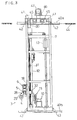
- Fig. 3 is a front view of the machine;
- Figs. 4(a) and 4(b) are enlarged side view of the machine; and
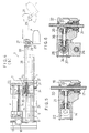
- Figs. 5 and 6 are enlarged front view of the machine.
- With reference to the accompanying drawings, preferred embodiments according to the present invention will be described below.
- In Fig. 1, numeral 1 denotes a painting booth,
numeral 2 denotes a conveyer device for conveying an automobile body (A) to be painted as a work object inside the booth, andnumeral 3 denotes a side automatic painting device for spraying paint on a side surface of the automobile body A. - As shown in Figs. 2 and 4, the side
automatic painting device 3 basically comprises a horizontally movable unit 5 (shown in a bold line in Fig. 4(b)) acting as a first movable portion having aspray nozzle 4 supportedly connected thereto, a lift unit 6 (shown in a bold line in Fig. 4(a)) acting as a second movable portion, and abase unit 7. The horizontallymovable unit 5 is connectably supported by thelift unit 6 to be movable in a direction toward and away from the automobile body A. Thelift unit 6 is connectably supported by thebase unit 7 to be vertically movable, i.e. to be movable in a specified direction perpendicular to the moving direction of the horizontalmovable unit 5. Thus, thespray nozzle 4 is supported by thebase unit 7 acting as a supporting portion through the serially arranged horizontalmovable unit 5 and thelift unit 6. - The
spray nozzle 4 is further connectably supported by the horizontalmovable unit 5 to be vertically oscillatable for varying its direction, i.e. to be oscillatable in the moving direction of thelift unit 6. - With the above noted structure, the horizontal
movable unit 5 is moved to maintain a constant distance between thespray nozzle 4 and the side surface of the automobile body A, thespray nozzle 4 is pivotable to keep its spraying direction constantly normal to and oppose to the side surface of the automobile body A, and thelift unit 6 is vertically reciprocated, whereby the curved side surface of the automobile body A is appropriately painted. - The
base unit 7 is connectably supported by a side wall of the painting booth 1 to be movable in the conveying direction of the automobile body A. By moving thebase unit 7, a position of the sideautomatic painting device 3 is suitably variable in the conveying direction of the automobile body A with a variety of working conditions in a spray painting operation. - The
lift unit 6 has a drivingstructure including sprockets base unit 7, and achain 9 extending between and wounded around thesprockets lift unit 6 is connected to a portion of thechain 9. Thelower sprocket 8b is rotated by a liftunit driving motor 10 acting as a first actuator through achain transmission mechanism 11, and is repeatedly rotated in a reverse direction, thereby to vertically reciprocate thelift unit 6. - Numeral 12 denotes a lifting guide mounted on the
base unit 7 for guiding the vertical movement of thelift unit 6. Numeral 13 denotes a balance weight for compensating the self-weight of thelift unit 6. - The horizontally
movable unit 5 has a driving structure including ascrew shaft 14 mounted on thelift unit 6, and a ball screwedportion 15 fitted on thescrew shaft 14, the ball screw portion and the screw shaft being mounted on the horizontalmovable unit 5. - A horizontally movable
unit driving motor 16 acting as a second actuator is mounted above thebase unit 7. A verticalfirst spline shaft 17 rotated by themotor 16 is mounted on thebase unit 7 extending through afirst gearbox 18 provided in thelift unit 6. - As seen from Fig. 5, a
first ball spline 19 is mounted on thefirst gearbox 18 for slidably fitting on thefirst spline shaft 17 to receive rotation of thefirst spline shaft 17. Rotation of thefirst ball spline 19 is transmitted to thescrew shaft 14 through a firstbevel gear mechanism 20, arelay shaft 21 and a secondbevel gear mechanism 22. - More particularly, the
lift unit 6 of the two movable units which is positioned closer to thebase unit 7 in the supporting order is adapted to be vertically movable by sliding movement of thefirst ball spline 19 relative to thefirst spline shaft 17. In this condition, a transmission mechanism for transmitting drive of the horizontal movableunit driving motor 16 mounted on thebase unit 7 to the horizontalmovable unit 5 positioned closer to thespray nozzle 4 in the supporting order includes thefirst spline shaft 17, thefirst ball spline 19, the firstbevel gear mechanism 20, therelay shaft 21, the secondbevel gear mechanism 22, thescrew shaft 14 and the ball screwedportion 15. Thescrew shaft 14 mounted on thelift unit 6 is rotated by the horizontal movableunit driving motor 16 mounted on thebase unit 7, whereby thehorizontal unit 5 is movable in the direction toward and away from the automobile body A by screw engagement between thescrew shaft 14 and the ball screwedportion 15. -
Numerals movable unit 5, respectively. - The
spray nozzle 4 has a driving structure including athird spline shaft 26 mounted on the horizontalmovable unit 5. Rotation of thethird spline shaft 26 is transmitted to anozzle holder 29 through a FRP insulatedshaft 38, aworm gear mechanism 27 and asupport shaft 28, thereby to pivot thespray nozzle 4. - A
motor 30 acting as a third actuator for varying the nozzle direction is mounted above thebase unit 7. A verticalsecond spline shaft 31 rotated by themotor 30 is mounted on thebase unit 7 extending through asecond gearbox 32 provided in thelift unit 6. - As shown in Fig. 6, a
second ball spline 33 is mounted on thesecond gearbox 32 for slidably fitting on thesecond spline shaft 31 to receive rotation of thesecond spline shaft 31. Also, athird ball spline 34 is mounted on thesecond gearbox 32 for relatively slidably fitting on thethird spline shaft 26 to transmit drive to thethird spline shaft 26. Thus, rotation of thesecond ball spline 33 is transmitted to thethird ball spline 34 through a thirdbevel gear mechanism 35, arelay shaft 36 and a fourthbevel gear mechanism 37. - More particularly, sliding movement of the
second ball spline 33 relative to thesecond spline shaft 31 permits vertical movement of thelift unit 6, and sliding movement of thethird ball spline 34 relative to thethird spline shaft 26 permits movement of the horizontalmovable unit 5. Thus, a transmission mechanism for transmitting drive of the nozzledirection varying motor 30 mounted on thebase unit 7 to thespray nozzle 4 includes thesecond spline shaft 31, thesecond ball spline 33, the thirdbevel gear mechanism 35, therelay shaft 36, the fourthbevel gear mechanism 37, thethird ball spline 34, thethird spline shaft 26, the insulatedshaft 38, theworm gear mechanism 27, thesupport shaft 28 and thenozzle holder 29. The nozzledirection varying motor 30 mounted on thebase unit 7 rotates thethird spline shaft 26 on the horizontallymovable unit 5, thereby to pivot thespray nozzle 4 to change its direction. - Numeral 39 denotes a FRP cylindrical insulated support for supporting an extreme end portion of the horizontal
movable unit 5. Theinsulated support 39 in combination with the insulatedshaft 38 electrically insulates thespray nozzle 4 having a high voltage portion for electrostatic spray painting from the sideautomatic painting device 3. - A moving structure of the
base unit 7 in the conveying direction of the automobile body, i.e. a moving structure of the sideautomatic painting device 3 per se will be set forth next. The side wall of the painting booth 1 is provided withrails base unit 7 is provided afirst roller 41 rolling on theupper rail 40a with a load of thebase unit 7, and a pair ofsecond rollers 42 sandwiching theupper rail 40a in a transverse direction of theupper rail 40a. A pair ofthird rollers 43 is mounted in the lower portion of thebase unit 7 to sandwich thelower rail 40b in the transverse direction of thelower rail 40b, thereby to guide thebase unit 7 in the conveying direction of the automobile body. - A
chain 44 having fixed opposite ends for receiving moving reaction is mounted on the upper portion of the side wall of the painting booth along theupper rail 40a. On thebase unit 7 are mounted a pair of idlingsprockets 45 meshing with thechain 44, a drivingsprocket 46 meshing with an inner surface of a U-shaped chain portion resulting from winding around the idlingsprockets 45, and a baseunit driving motor 41 for rotating the drivingsprocket 46, respectively. Rotation of the drivingsprocket 46 by themotor 47 allows thebase unit 7 to move in the conveying direction of the automobile body to vary the position of the sideautomatic painting device 3. -
Numeral 48 denotes a box for defining an operator's booth integrally formed with the side wall of the painting booth 1. Thisbox 48 is divided into anupper chamber 48a, an operator'sbooth 48b, and alower chamber 48c bypartitions upper chamber 48a houses anaccommodating unit 51 together with theupper rail 40a and thereaction receiving chain 44 to give an allowance to a painting hose, a pneumatic hose, an electric cable and the like extending to the sideautomatic painting device 3 for varying the position of the sideautomatic painting device 3. Thelower chamber 48c houses control panels including an electric control panel, a pneumatic control panel and the like. - A
viewer window 52 is provided in a portion of the side wall of the painting booth 1 corresponding to the operator'sbooth 48b. - The lift
unit driving motor 10, the horizontal movableunit driving motor 16 and the nozzledirection varying motor 30 are unitedly controlled by a controller (not shown) based on a predetermined program with circumstances including a kind of the automobile body A, a conveying speed of the automobile body A, a spray painting mode with respect to the side surface of the automobile body A and the like. When these circumstances vary, the program is modified to change the moving speed and a vertical reciprocating width of thelift unit 6, and the moving mode of the horizontalmovable unit 5 and the oscillating mode of thespray nozzle 4 along with the vertical movement of thelift unit 6, as a result of which a suitable spray painting operation can be effected in response to any conditions. - Other embodiments will be listed below.
- (i) The first movable portion (corresponding to the horizontal
movable unit 5 in the foregoing embodiment) movable in the direction toward and away from the work object A and the second movable portion (corresponding to thelift unit 6 in the foregoing embodiment) movable in the specified direction perpendicular to the moving direction of the firstmovable unit 5 may be structurally modified in various ways. - (ii) In supporting the
spray nozzle 4 by the supporting portion (corresponding to thebase unit 7 in the foregoing embodiment) through the serially arranged first and secondmovable portions movable portion 5 is positioned closer to thespray nozzle 4 and the secondmovable portion 6 is positioned closer to the supportingportion 7 in the supporting order in the foregoing embodiment. Alternatively, the secondmovable portion 6 may be positioned closer to thespray nozzle 4, and the firstmovable portion 5 may be positioned closer to the supportingportion 7. - (iii) The moving direction of the first
movable portion 5, i.e. the direction toward and away from the work object A, is not limited to the horizontal direction. Likewise, the moving direction of the secondmovable portion 6, i.e. the specified direction perpendicular to the moving direction of the firstmovable portion 5, is not limited to the vertical direction. - (iv) While one of the first and second
movable portions portion 7 in the supporting order is allowed to move, the transmission mechanism for transmitting drive of the actuator mounted on the supporting portion 7 (corresponding to the motor in the foregoing embodiment) to the movable portion positioned closer to thespray nozzle 4 in the supporting order may be modified in various ways. - (v) While the first and second
movable portions motor 30 in the foregoing embodiment) to thespray nozzle 4 may be modified in various ways. - (vi) In addition, the
third actuator 30 may be mounted on either one of the firstmovable portion 5 or the secondmovable portion 6. Also, the direction varying movement by oscillation of thespray nozzle 4 may be omitted. - (vii) The
first actuator 16 for the firstmovable portion 5, thesecond actuator 10 for the secondmovable portion 6, and thethird actuator 30 for varying the nozzle direction are not limited to the motors, but may be drive cylinders. - (viii) The work object A is not limited to the automobile body, but may be any objects including a casing for domestic electric products, a railroad vehicle and the like.
Claims (6)
- An automatic spray painting machine having:
a first movable portion (5) movable in a direction to and away from a work object (A);
a second movable portion (6) movable in a predetermined direction perpendicular to the moving direction of said first movable portion (5);
a supporting portion (7) for supporting a spray nozzle (4) through the serially arranged first and second portions (5,6);
a first actuator (10) for moving said second movable portion (6); and
a second actuator (16) for moving said first movable portion (5);
said first and second actuators (10, 16) being mounted on said supporting portion (7);
a transmission mechanism (17, 19, 20, 21, 22, 14, 15) for transmitting, to one of said first and second movable portions (5), (6) whichever is positioned closer to said spray nozzle in the supporting order, drive of one of said first and second actuators (10), (16) corresponding thereto, said transmission mechanism effecting the drive transmission while allowing movement of the other movable portion (6) or (5) positioned closer to said support portion (7) in said supporting order; characterized by a first roller (41) provided at an upper position of said support portion (7) for receiving load of this support portion (7), said first roller (41) rolling on an upper rail (40a);
a pair of second rollers (42) provided at upper positions of said support portion (7) for sandwiching said upper rail (40a) across a width thereof,
a pair of third rollers (43) provided at lower positions of said support portion (7) for sandwiching a lower rail (40b) across a width thereof; and
said support portion (7) being displaceable/adjustable in position in the direction of conveyance of said work object (A). - An automatic spray painting machine as claimed in Claim 1 characterized in that the transmission mechanism comprises;
a first spline shaft (17) rotated by the second actuator (16),
a first ball spline (19) slidably fitted on the first spline shaft (17) for receiving rotation of the first spline shaft,
a first bevel gear mechanism (20), a relay shaft (21) and a second bevel gear mechanism (22) for transmitting rotation of the first ball spline (19),
a screw shaft (14) receiving rotation of the first ball spline (19) through the first bevel gear mechanism (20), the relay shaft (21) and the second bevel gear mechanism (22), and
a ball screwed portion (15) fitted on the screw shaft (14) for transmitting rotation of the screw shaft to the first movable portion (5). - An automatic spray painting machine as claimed in Claim 1 characterized in that the spray nozzle (4) is directionally variable by rotation in the moving direction of the second movable portion (6), the supporting portion (7) carries a third actuator (30) for pivoting the spray nozzle (4), and wherein a transmission mechanism (31, 33, 35, 36, 37, 34, 26, 38, 27, 28, 29) for varying the nozzle direction and transmitting drive of the third actuator (30) to the spray nozzle (4) effects drive transmission, with the first and second movable portions (5, 6) being allowed to move.
- An automatic spray painting machine as claimed in Claim 3 characterized in that the transmission mechanism comprises;
a second spline shaft (31) rotated by the third actuator (30),
a second ball spline (33) slidably fitted on the second spline shaft (31) for receiving rotation of the spline shaft,
a third bevel gear mechanism (35), a relay shaft (36) and a fourth bevel gear mechanism (37) for transmitting rotation of the second ball spline (33),
a third ball spline (34) for receiving rotation of the second ball spline (33) through the third bevel gear mechanism (35), the relay shaft (36) and the fourth bevel gear mechanism (37),
a third spline shaft (26) fitted on the third ball spline (34) thereby to receive rotation,
an insulated shaft (38), a worm gear mechanism (27) and a support shaft (28) for transmitting drive of the third spline shaft (26) to the spray nozzle (4), and
a nozzle holder (29) for pivoting the spray nozzle (4) through the insulated shaft (38), the worm gear mechanism (27) and the support shaft (28). - An automatic spray painting machine as claimed in Claim 1, characterized in that said second movable portion (6) includes a balance weight (13) for compensating for weight of said second movable portion (6).
- An automatic spray painting machine as claimed in Claim 1, characterized in that said spray nozzle (4) is supported to said support portion (7) by an insulated shaft (38) and an insulated support (39), so that said spray nozzle is insulated from a body of said automatic spray painting machine.
Applications Claiming Priority (2)
| Application Number | Priority Date | Filing Date | Title |
|---|---|---|---|
| JP304202/89 | 1989-11-21 | ||
| JP1304202A JPH03161068A (en) | 1989-11-21 | 1989-11-21 | Automatic coating machine |
Publications (3)
| Publication Number | Publication Date |
|---|---|
| EP0429289A2 EP0429289A2 (en) | 1991-05-29 |
| EP0429289A3 EP0429289A3 (en) | 1992-01-02 |
| EP0429289B1 true EP0429289B1 (en) | 1994-08-17 |
Family
ID=17930247
Family Applications (1)
| Application Number | Title | Priority Date | Filing Date |
|---|---|---|---|
| EP90312605A Expired - Lifetime EP0429289B1 (en) | 1989-11-21 | 1990-11-20 | Automatic spray painting machine |
Country Status (6)
| Country | Link |
|---|---|
| US (1) | US5111997A (en) |
| EP (1) | EP0429289B1 (en) |
| JP (1) | JPH03161068A (en) |
| CA (1) | CA2030353C (en) |
| DE (1) | DE69011630T2 (en) |
| ES (1) | ES2062413T3 (en) |
Families Citing this family (20)
| Publication number | Priority date | Publication date | Assignee | Title |
|---|---|---|---|---|
| US5878952A (en) * | 1995-05-08 | 1999-03-09 | Powell; Thomas M. | Modular robot auxiliary axis system |
| US5968271A (en) * | 1997-02-10 | 1999-10-19 | Imax Corporation | Painting method and apparatus |
| DE102004009204B4 (en) * | 2004-02-25 | 2009-08-06 | Electrolux Home Products Corp. N.V. | Method for coating a body |
| KR100935664B1 (en) * | 2009-04-24 | 2010-01-14 | 주식회사 파스코 | A device for painting of pipe |
| CN105289875A (en) * | 2015-08-30 | 2016-02-03 | 江苏邦威机械制造有限公司 | Automatic corrosion preventing machine for PCCP pipes |
| CA2908193C (en) * | 2015-10-06 | 2017-12-19 | Malcolm Macduff | Supply manifold with rotatable slider |
| RU2669107C1 (en) * | 2017-02-06 | 2018-10-08 | Малколм МАКДАФФ | Liquid distribution manifold |
| CN107159508B (en) * | 2017-06-28 | 2018-02-23 | 湖南长信华森环保建筑铝模有限公司 | A kind of environmentally friendly mopping equipment |
| US11500400B2 (en) * | 2018-07-30 | 2022-11-15 | Fresenius Medical Care Holdings, Inc. | Valve actuation systems and related methods |
| AU2019315359B2 (en) | 2018-07-31 | 2024-06-20 | Fresenius Medical Care Holdings, Inc. | Rotary valves for dialysis systems |
| CN113423456B (en) | 2018-12-07 | 2024-03-19 | 费森尤斯医疗保健控股公司 | Rotary valves for managing fluid flow in medical systems |
| CN109622263A (en) * | 2019-01-09 | 2019-04-16 | 郑州航空工业管理学院 | A kind of spray-painting plant for electronic product casing processing |
| CN110449298B (en) * | 2019-07-04 | 2021-04-06 | 江苏长虹机械设计院有限公司 | Vehicle spraying device convenient to control spraying amount |
| AU2020324956B2 (en) | 2019-08-05 | 2024-08-22 | Fresenius Medical Care Holdings, Inc. | Conductivity control systems |
| CN110639743B (en) * | 2019-10-31 | 2021-07-13 | 苏州知瑞光电材料科技有限公司 | Graphene layer coating device |
| CN115315280A (en) | 2019-12-12 | 2022-11-08 | 费森尤斯医疗保健控股公司 | Blood treatment system |
| CN111359813A (en) * | 2020-03-04 | 2020-07-03 | 优固得建筑装配科技有限公司 | Be used for anticorrosive spraying device of chimney inner wall and an inner wall gallows |
| CN111644300B (en) * | 2020-06-22 | 2021-06-15 | 刘根深 | Quick paint spraying maintenance equipment for outdoor traffic indication column |
| CN115178409A (en) * | 2022-08-24 | 2022-10-14 | 中国十七冶集团有限公司 | Painting equipment for decoration project |
| CN117101924B (en) * | 2023-10-25 | 2024-02-02 | 江苏星瑞防务科技有限公司 | Surface boat panel spraying equipment |
Family Cites Families (9)
| Publication number | Priority date | Publication date | Assignee | Title |
|---|---|---|---|---|
| GB2142257B (en) * | 1983-07-02 | 1986-11-26 | Gen Motors Overseas | Adhesive application apparatus |
| US4616782A (en) * | 1985-01-22 | 1986-10-14 | Nordson Corporation | Spray gun carriage assembly having inertial damping and a variable stroke |
| US4656049A (en) * | 1986-03-10 | 1987-04-07 | General Dynamics Corp. Space Systems Division | Method and apparatus for the proper quantized application of a mold release agent onto a mold surface |
| US4931322A (en) * | 1986-04-01 | 1990-06-05 | Honda Giken Kogyo Kabushiki | Method and apparatus for painting object |
| JPS63201667A (en) * | 1987-02-17 | 1988-08-19 | Canon Inc | Developer for electrostatic image development |
| FI872244A7 (en) * | 1987-05-21 | 1988-11-22 | Betemi Oy | Concrete element manufacturing method. |
| DE3813058A1 (en) * | 1988-04-19 | 1989-11-09 | Devilbiss Gmbh | FREE PROGRAMMABLE CONTOUR MACHINE |
| JPH026868A (en) * | 1988-06-25 | 1990-01-11 | Taikisha Ltd | Method for setting coating device in coating booth and coating machine operating unit constituting part of coating booth |
| JPH06226B2 (en) * | 1988-09-22 | 1994-01-05 | 本田技研工業株式会社 | Painting method |
-
1989
- 1989-11-21 JP JP1304202A patent/JPH03161068A/en active Pending
-
1990
- 1990-11-19 US US07/615,229 patent/US5111997A/en not_active Expired - Fee Related
- 1990-11-20 ES ES90312605T patent/ES2062413T3/en not_active Expired - Lifetime
- 1990-11-20 CA CA002030353A patent/CA2030353C/en not_active Expired - Fee Related
- 1990-11-20 EP EP90312605A patent/EP0429289B1/en not_active Expired - Lifetime
- 1990-11-20 DE DE69011630T patent/DE69011630T2/en not_active Expired - Fee Related
Also Published As
| Publication number | Publication date |
|---|---|
| CA2030353A1 (en) | 1991-05-22 |
| CA2030353C (en) | 1999-01-12 |
| US5111997A (en) | 1992-05-12 |
| EP0429289A2 (en) | 1991-05-29 |
| DE69011630T2 (en) | 1995-01-12 |
| ES2062413T3 (en) | 1994-12-16 |
| JPH03161068A (en) | 1991-07-11 |
| DE69011630D1 (en) | 1994-09-22 |
| EP0429289A3 (en) | 1992-01-02 |
Similar Documents
| Publication | Publication Date | Title |
|---|---|---|
| US5111997A (en) | Automatic spray painting machine | |
| EP0189617B1 (en) | Improved floor sanding and polishing machine | |
| KR100381504B1 (en) | Articulated Robot | |
| US4762013A (en) | Reciprocating device for spray coating | |
| US5092307A (en) | Roof machine for paint finishing | |
| US4864965A (en) | Automatic painting apparatus | |
| CA1329478C (en) | Contour following apparatus for positioning spray guns | |
| US4733576A (en) | Multi-purpose industrial robot | |
| CN209855168U (en) | Spraying robot | |
| EP0421791B1 (en) | Spray painting system | |
| CN216780605U (en) | Automatic welding moving track control device for wave-shaped plate of thin film type liquid cargo containment system | |
| ITTO950120A1 (en) | TROLLEY TO DRIVE A TOOL ALONG A TRAJECTORY SPECIFIED ON A PIECE TO BE WORKED. | |
| CN117922414A (en) | Four-wheel drive chassis maintenance robot with chain transmission in box girder cavity and navigation operation method thereof | |
| CN216730190U (en) | Tube screen surfacing platform | |
| JPH0741486B2 (en) | Screw tightening device | |
| CN215469655U (en) | Supporting device for section bar cutting and cutting machine | |
| KR102965213B1 (en) | Mixer car and 3D printer for construction including the same | |
| KR940005481B1 (en) | Transmission | |
| KR0116881Y1 (en) | Vertical reciprocating device of product spray gun which can operate up and down simultaneously with one driving part | |
| CN223628331U (en) | Angle adjustment's dust device for urban and rural planning | |
| US5588795A (en) | Handling apparatus | |
| CN223385393U (en) | Stop mechanism and transfer device | |
| CN222332437U (en) | Milling machine belt frame | |
| CN114382266A (en) | Floating robot | |
| JPS6231172Y2 (en) |
Legal Events
| Date | Code | Title | Description |
|---|---|---|---|
| PUAI | Public reference made under article 153(3) epc to a published international application that has entered the european phase |
Free format text: ORIGINAL CODE: 0009012 |
|
| 17P | Request for examination filed |
Effective date: 19901210 |
|
| AK | Designated contracting states |
Kind code of ref document: A2 Designated state(s): DE ES FR GB |
|
| PUAL | Search report despatched |
Free format text: ORIGINAL CODE: 0009013 |
|
| AK | Designated contracting states |
Kind code of ref document: A3 Designated state(s): DE ES FR GB |
|
| 17Q | First examination report despatched |
Effective date: 19930521 |
|
| GRAA | (expected) grant |
Free format text: ORIGINAL CODE: 0009210 |
|
| AK | Designated contracting states |
Kind code of ref document: B1 Designated state(s): DE ES FR GB |
|
| REF | Corresponds to: |
Ref document number: 69011630 Country of ref document: DE Date of ref document: 19940922 |
|
| ET | Fr: translation filed | ||
| REG | Reference to a national code |
Ref country code: ES Ref legal event code: FG2A Ref document number: 2062413 Country of ref document: ES Kind code of ref document: T3 |
|
| PLBE | No opposition filed within time limit |
Free format text: ORIGINAL CODE: 0009261 |
|
| STAA | Information on the status of an ep patent application or granted ep patent |
Free format text: STATUS: NO OPPOSITION FILED WITHIN TIME LIMIT |
|
| 26N | No opposition filed | ||
| PGFP | Annual fee paid to national office [announced via postgrant information from national office to epo] |
Ref country code: ES Payment date: 19971112 Year of fee payment: 8 |
|
| PGFP | Annual fee paid to national office [announced via postgrant information from national office to epo] |
Ref country code: GB Payment date: 19981026 Year of fee payment: 9 |
|
| PG25 | Lapsed in a contracting state [announced via postgrant information from national office to epo] |
Ref country code: ES Free format text: LAPSE BECAUSE OF NON-PAYMENT OF DUE FEES Effective date: 19981121 |
|
| PG25 | Lapsed in a contracting state [announced via postgrant information from national office to epo] |
Ref country code: GB Free format text: LAPSE BECAUSE OF NON-PAYMENT OF DUE FEES Effective date: 19991120 |
|
| GBPC | Gb: european patent ceased through non-payment of renewal fee |
Effective date: 19991120 |
|
| REG | Reference to a national code |
Ref country code: ES Ref legal event code: FD2A Effective date: 20010503 |
|
| PGFP | Annual fee paid to national office [announced via postgrant information from national office to epo] |
Ref country code: FR Payment date: 20021128 Year of fee payment: 13 |
|
| PGFP | Annual fee paid to national office [announced via postgrant information from national office to epo] |
Ref country code: DE Payment date: 20021129 Year of fee payment: 13 |
|
| PG25 | Lapsed in a contracting state [announced via postgrant information from national office to epo] |
Ref country code: DE Free format text: LAPSE BECAUSE OF NON-PAYMENT OF DUE FEES Effective date: 20040602 |
|
| PG25 | Lapsed in a contracting state [announced via postgrant information from national office to epo] |
Ref country code: FR Free format text: LAPSE BECAUSE OF NON-PAYMENT OF DUE FEES Effective date: 20040730 |
|
| REG | Reference to a national code |
Ref country code: FR Ref legal event code: ST |