EP0429024A2 - Bandleitersatz und Verfahren - Google Patents
Bandleitersatz und Verfahren Download PDFInfo
- Publication number
- EP0429024A2 EP0429024A2 EP90121985A EP90121985A EP0429024A2 EP 0429024 A2 EP0429024 A2 EP 0429024A2 EP 90121985 A EP90121985 A EP 90121985A EP 90121985 A EP90121985 A EP 90121985A EP 0429024 A2 EP0429024 A2 EP 0429024A2
- Authority
- EP
- European Patent Office
- Prior art keywords
- conductor
- ribbon
- ribbons
- support frame
- conductor ribbons
- Prior art date
- Legal status (The legal status is an assumption and is not a legal conclusion. Google has not performed a legal analysis and makes no representation as to the accuracy of the status listed.)
- Withdrawn
Links
Images
Classifications
-
- A—HUMAN NECESSITIES
- A61—MEDICAL OR VETERINARY SCIENCE; HYGIENE
- A61N—ELECTROTHERAPY; MAGNETOTHERAPY; RADIATION THERAPY; ULTRASOUND THERAPY
- A61N1/00—Electrotherapy; Circuits therefor
- A61N1/18—Applying electric currents by contact electrodes
- A61N1/32—Applying electric currents by contact electrodes alternating or intermittent currents
- A61N1/36—Applying electric currents by contact electrodes alternating or intermittent currents for stimulation
- A61N1/372—Arrangements in connection with the implantation of stimulators
- A61N1/375—Constructional arrangements, e.g. casings
- A61N1/3752—Details of casing-lead connections
Definitions
- This invention relates generally to improvements in devices and methods for conductively interconnecting electrical components in an implantable medical device or the like. More particularly, this invention relates to a conductor set and related production and installation method for quickly and easily interconnecting multiple electrical components. The invention is particularly designed to facilitate electrical interconnection of pacemaker lead connector blocks with feedthrough terminals of an implantable heart pacemaker unit or similar device.
- the implantable device comprises a pacemaker unit having an appropriate electrical power supply and related control circuitry for use in electrically stimulating a patient muscle, such as the heart.
- a pacemaker unit commonly includes an hermetically sealed case or housing within which the power supply and control circuitry are protectively encased, in combination with one or more conductive pacemaker leads extending from the housing to the selected muscle structure within the patient.
- Feedthrough terminals on the pacemaker housing accommodate hermetically sealed passage of electrical conductors to the housing exterior for appropriate connection to the pacemaker lead or leads, typically through the use of so-called connector blocks having set screws or the like for secure lead attachment.
- the connector blocks and associated feedthrough conductors disposed externally of the pacemaker housing are commonly encased within an hermetically sealed head structure, such as an insulative head of cast epoxy or the like.
- a ribbon conductor set for facilitated electrical connection of feedthrough terminals and lead connector blocks in an implantable medical device, such as a heart pacemaker unit or the like.
- the ribbon conductor set comprises a plurality of conductor ribbons formed as a set in predetermined number, spacing, and geometry to extend between multiple conductors at one or more feedthrough terminals and lead connector blocks associated with individually with the feedthrough conductors.
- the conductor ribbons are adapted for installation as a group into a pacemaker unit, and in an orientation which accommodates relatively simple connection to the feedthrough terminals and connector blocks by spot welding or the like.
- the ribbon conductor set comprises the plurality of conductor ribbons formed from conductive sheet stock by etching and/or appropriate die cutting.
- the conductor ribbons are arranged in spatial array to avoid short circuit contact therebetween and further to have individualized shapes each adapted for connection between a designated feedthrough terminal conductor and associated lead connector block of the pacemaker unit.
- the conductor ribbons are initially supported by narrow frets from a support frame which is also formed from the conductive sheet stock.
- a stamping step is typically included to provide the conductor ribbons with a three-dimensional shape as may be required for connection in mutually spaced array to the feedthrough terminal conductors and lead connector blocks. Additional spacer means such as a bead of an insulative epoxy and/or a strip of insulative tape may be applied to the conductor ribbons to maintain the ribbons in spaced relation during handling and installation.
- a fixture for supporting a pacemaker unit housing having feedthrough terminals thereon in predetermined positional relation to pacemaker lead connector blocks.
- the fixture includes locator means for receiving and supporting the housing and the connector blocks at the predetermined relative positions.
- the ribbon conductor set is then placed over the pacemaker housing and the lead connector blocks, with the support frame and fixture including registration means such as a locator pin received into a frame aperture for accurately positioning the ribbon set.
- the individual conductor ribbons are each exposed in this manner for easy access and fixation to the feedthrough terminals and connector blocks by spot welding or the like.
- the support frame is then easily removed from the conductor ribbons by trimming at the frets, whereupon the entire subassembly including the conductor ribbons, connector blocks and feedthrough terminals may be encapsulated within an insulating head of cast epoxy or the like.
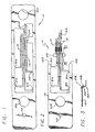
- a ribbon conductor set referred to generally in FIGURE 1 by the reference numeral 10 is provided for quickly and easily interconnecting electrical components in an implantable medical device, such as a heart pacemaker unit 12 or the like as viewed in FIG. 8.
- the ribbon conductor set 10 provides a plurality of conductor ribbons 14 in a predetermined shape and spatial array in accordance with the geometry of the electrical components to be interconnected.
- This shaped array of conductor ribbons 14 is supported as a unit or group by an integral support frame 16 for facilitated handling and placement in the course of connection to the associated electrical components.
- the ribbon conductor set 10 of the present invention is designed particularly for use in an implantable medical device such as a heart pacemaker unit 12 (FIG. 8).
- heart pacemaker units are generally known in the art for use in electrical stimulation of the heart muscle to regulate patient heartbeat in a controlled manner.
- the pacemaker unit 12 normally includes an appropriate power source and related electronic circuitry encased within a compact, hermetically sealed housing or case 18 adapted for implantation directly into the body of a patient at a selected convenient location.
- the unit produces a timed sequence of pacing pulses which are coupled to one or more conductive pacemaker leads 20, with the illustrative drawings depicting the pacemaker unit 12 to include a pair of pacemaker leads 20 for so-called duplex mode operation.
- the pacemaker leads 20 extend from the unit housing 18 for implantation of their distal ends (not shown) into target muscle tissue to be stimulated.
- the pacemaker unit 12 includes a head 22 on the unit housing 18, wherein the head 22 includes means for electromechanically anchoring the pacemaker leads 20 in conductive relation with the pacing signals generated by the circuitry components within the housing 18. More specifically, the pacemaker housing 18 defines a relatively flat mounting platform 24 at one edge thereof. One or more so-called feedthrough terminals 26 project upwardly from this platform and provide hermetically sealed structures of a type known in the art for passing electrical conductors from the interior of the housing 18. The illustrative drawings show a pair of feedthrough terminals 26 each including a pair of short upstanding conductors 28, thereby providing a total of four conductors 28 for use in duplex mode pacemaker unit operation.
- feedthrough terminal conductors 28 are respectively connected by means of the ribbon conductor set 10 of the present invention to a corresponding set of four connector blocks 30 adapted for electromechanical connection to the pacemaker leads 20. Subsequent to electrical interconnection of the feedthrough terminal conductors 28 with the connector blocks 30, as will be described in more detail, these components are encapsulated within a block of insulative epoxy material or the like which is cast in place to define the head 22 maintaining the various components in the desired hermetically sealed and predetermined interspatial relation.
- the apparatus and method of the present invention is designed to facilitate the process of interconnecting the feedthrough terminal conductors 28 with the connector blocks 30.
- the ribbon conductor set 10 provides a preshaped and prespaced array of conductive elements which can be handled as a unitary set or group for rapid yet accurate placement and appropriate connection by resistance spot welding or the like.
- the ribbon set 10 is adapted for cost-efficient manufacture by die cutting and/or stamping processes to yield detailed yet reproducible ribbon shapes in conformance with the geometry of the feedthrough terminals and connector blocks to be interconnected.
- the individual conductor ribbons 14 are maintained in sufficient spacing to substantially eliminate risk of short circuit failures.
- the ribbon conductor set 10 is formed from sheet stock of a suitable conductive material to include the set of conductor ribbons 14 carried within the surrounding support frame 16.
- the support frame 16 is generally coplanar with the conductor ribbons 14, with each ribbon 14 having an individualized elongated shape supported at its opposite ends by a pair of narrow frets 34 on the support frame 16.
- this frame and ribbon set combination is formed by etching thin sheet stock of stainless steel or platinum alloy or the like to produce the desired ribbon pattern, wherein this etched sheet stock may have a thickness on the order of a few thousandths of an inch. Alternately, cutting and/or stamping processes may be used.
- the support frame 16 includes one or more large ports 36 formed therein to permit accurate placement into process tools and fixtures.
- FIGS. 2 and 3 illustrate the ribbon conductor set subsequent to a stamping and cutting process step for shaping the individual conductor ribbons 14 to an appropriate three-dimensional geometry. More specifically, the ribbon set can be seated into an appropriate die tool for shaping each ribbon 14 to include one or more bends deviating from the plane of the support frame 16.
- FIG. 3 illustrates all four ribbons 14 to include a common rearward bend 38 in close association with a return bend 40.
- FIG. 2 shows one of the ribbons 14 to include a generally semicircular bend 42 for clearance with a feedthrough terminal 26, as will become more apparent.
- a portion of the support frame 16 is desirably removed by trimming the frame at points 43 and 44, and by severing the frets 34 at one common end of the conductor ribbons 14.
- the conductor ribbons 14 project generally in somewhat cantilevered relation from the remaining portion of the support frame 32 which remains connected to the ribbons by means of the remaining frets 34.
- the conductor ribbons 14 are desirably provided with additional support means to maintain the inter-ribbon spacing and to minimize risk of ribbon damage during subsequent handling.
- additional support means to maintain the inter-ribbon spacing and to minimize risk of ribbon damage during subsequent handling.
- an elongated bead 46 of epoxy or the like may be placed and cured along the conductor ribbons 14 such as at the inboard side of the bend 38 to support the ribbons with respect to each other.
- a strip of tape 48 such as insulating tape of Kapton film or the like may be used as a temporary support for the fragile ribbons 14.
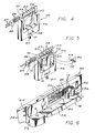
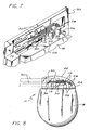
- a fixture 50 is depicted in FIGS. 4-7 for use in supporting the various components in a convenient arrangement during placement and mounting of the ribbon conductor set 10. More particularly, the illustrative fixture 50 includes a base plate 52 which cooperates with a short upstanding and generally U-shaped base wall 54 to define an open-sided cavity 56 (FIG. 4) for receiving the housing 18 of the pacemaker unit 12.
- a spring-loaded foot 58 is centrally located along the base wall 54 at a position opposite the open side thereof, and can be suitably manipulated by a knob 60 or the like and related spring 61 to press against the unit housing 18.
- This pressing action of the foot 58 advances one side edge of the housing platform 24 into seated relation with a short upstanding rib 62 on the base plate 52, thereby positively and firmly locking the unit housing 18 in a predetermined orientation within the fixture 50 (FIG. 5).
- Such placement of the unit housing 18 additionally positions the feedthrough terminals 26 and their respective short protruding conductors 28 at predetermined locations within the fixture.
- the connector blocks 30 are also mounted into the fixture 50 at predetermined positions.
- the connector blocks 30 are traditionally provided in interconnected pairs with each connector block having a flat rear face 30′ with a shallow threaded bore 29 formed therein. These threaded bores 29 are intended for subsequent reception of set screws (not shown) for use in locking connection to the pacemaker leads 20.
- the threaded bores 29 in the connector blocks 30 are open and provide convenient receptacles for short positioning pins 63 on the fixture base plate 52, such that the connector blocks 30 are predeterminably positioned relative to the feedthrough terminals 26.
- Additional anchoring of the pairs of connector blocks 30 may be provided by temporary insertion of lead pins 64 into the connector blocks, wherein these lead pins 64 are conveniently mounted on the fixture for retractable movement limited by enlarged pin spools 66 adapted to abut a pair of raised stops 68 and 70.
- a short locator pin 72 on the fixture 50 is adapted for reception into a mating aperture 74 in the support frame 16 to predetermine the position of the ribbon set (FIG. 6)
- the free ends of the individual conductor ribbons 14 align easily and accurately with the respective feedthrough terminal conductors 28, and the opposite fret-supported ends of the ribbons 14 align with the respective connector blocks 30.
- both ends of each ribbon 14 can be attached quickly and easily to the associated components by resistance spot welding or the like, and the remainder portion of the support frame 16 can be removed quickly and easily by severing at the frets 34.
- the strip of support tape 48 if used, may be removed at a convenient time typically subsequent to ribbon attachment to the underlying components.
- the resultant head subassembly including the connector blocks 30 interconnected via the conductor ribbons 14 with the feedthrough conductors 28, provides an accurate and highly attractive electrical interconnection.
- the pacemaker unit 12 including this head subassembly is removed from the fixture 50 and appropriately processed to cast the epoxy head 22.
- This head 22 as viewed in FIG. 8, encapsulates the electrical components with an insulative and hermetic seal material.
- This epoxy head further supports the components in the desired predetermined spatial relation, and in a manner which is fully compatible with the epoxy bead 46 (FIG. 3) used to support the ribbons 14 during processing.
- the ribbon conductor set 10 thus provides a simple apparatus and method for facilitated and accurate electrical interconnection of feedthrough terminals and lead connector blocks in a heart pacemaker or the like.
- the conductor ribbons 14 are preformed in a manner consistent with economical production processes, and in a manner permitting handling as a unitary group during installation procedures.
Landscapes
- Health & Medical Sciences (AREA)
- Engineering & Computer Science (AREA)
- Biomedical Technology (AREA)
- Nuclear Medicine, Radiotherapy & Molecular Imaging (AREA)
- Radiology & Medical Imaging (AREA)
- Life Sciences & Earth Sciences (AREA)
- Animal Behavior & Ethology (AREA)
- General Health & Medical Sciences (AREA)
- Public Health (AREA)
- Veterinary Medicine (AREA)
- Electrotherapy Devices (AREA)
Applications Claiming Priority (2)
| Application Number | Priority Date | Filing Date | Title |
|---|---|---|---|
| US439070 | 1989-11-20 | ||
| US07/439,070 US5067903A (en) | 1989-11-20 | 1989-11-20 | Ribbon conductor set and method |
Publications (2)
| Publication Number | Publication Date |
|---|---|
| EP0429024A2 true EP0429024A2 (de) | 1991-05-29 |
| EP0429024A3 EP0429024A3 (en) | 1992-08-12 |
Family
ID=23743172
Family Applications (1)
| Application Number | Title | Priority Date | Filing Date |
|---|---|---|---|
| EP19900121985 Withdrawn EP0429024A3 (en) | 1989-11-20 | 1990-11-16 | Ribbon conductor set and method |
Country Status (2)
| Country | Link |
|---|---|
| US (1) | US5067903A (de) |
| EP (1) | EP0429024A3 (de) |
Cited By (3)
| Publication number | Priority date | Publication date | Assignee | Title |
|---|---|---|---|---|
| WO1996014102A3 (en) * | 1994-11-04 | 1996-09-19 | Physio Control Corp | Communication interface for transmitting and receiving serial data between medical instruments |
| EP1795226A1 (de) | 2005-12-08 | 2007-06-13 | BIOTRONIK CRM Patent AG | Gehäuse für medizinisches Implantat |
| EP1795225A1 (de) | 2005-12-08 | 2007-06-13 | BIOTRONIK CRM Patent AG | Gehäuse für ein medizinisches Implantat |
Families Citing this family (13)
| Publication number | Priority date | Publication date | Assignee | Title |
|---|---|---|---|---|
| US5235742A (en) * | 1989-11-20 | 1993-08-17 | Siemens Pacesetter, Inc. | Method of making an implantable device |
| US5524338A (en) * | 1991-10-22 | 1996-06-11 | Pi Medical Corporation | Method of making implantable microelectrode |
| US5201903A (en) * | 1991-10-22 | 1993-04-13 | Pi (Medical) Corporation | Method of making a miniature multi-conductor electrical cable |
| US5571146A (en) * | 1995-10-31 | 1996-11-05 | Pacesetter, Inc. | Technique for welding dissimilar metals |
| US5877472A (en) * | 1996-02-22 | 1999-03-02 | Pacesetter, Inc. | System for laser-welding components of an implantable device |
| US5869804A (en) * | 1996-06-28 | 1999-02-09 | Pacesetter, Inc. | Laser-welded ball-and-socket connection |
| US6366820B1 (en) | 2000-03-01 | 2002-04-02 | Pacesetter, Inc. | Interconnection technique between a cable conductor and an electrode of an implantable medical device |
| US7274963B2 (en) * | 2002-12-16 | 2007-09-25 | Cardiac Pacemakers, Inc. | Interconnect for implantable medical device header |
| CN101572365B (zh) * | 2008-04-28 | 2011-10-05 | 富士康(昆山)电脑接插件有限公司 | 线缆连接器组件 |
| CN103153788A (zh) * | 2010-09-28 | 2013-06-12 | 萨博公司 | 用于对结构元件进行除冰的方法和装置 |
| WO2014138237A1 (en) * | 2013-03-05 | 2014-09-12 | Parviz Acquisitons Llc | Single surface electro-mechanical actuator assembly |
| JP6154493B2 (ja) | 2013-03-06 | 2017-06-28 | カーディアック ペースメイカーズ, インコーポレイテッド | ヘッダを備える植込み型装置およびヘッダの形成方法 |
| US10189572B2 (en) * | 2016-05-02 | 2019-01-29 | The Boeing Company | Systems and methods for preventing ice formation on portions of an aircraft |
Family Cites Families (6)
| Publication number | Priority date | Publication date | Assignee | Title |
|---|---|---|---|---|
| US3678385A (en) * | 1969-09-26 | 1972-07-18 | Amp Inc | Assembly and test device for microelectronic circuit members |
| US4041956A (en) * | 1976-02-17 | 1977-08-16 | Coratomic, Inc. | Pacemakers of low weight and method of making such pacemakers |
| US4357750A (en) * | 1976-06-21 | 1982-11-09 | Advanced Circuit Technology Inc. | Jumper cable |
| WO1981000329A1 (fr) * | 1979-07-18 | 1981-02-05 | Mitsubishi Electric Corp | Bornes de fils |
| US4806409A (en) * | 1987-05-20 | 1989-02-21 | Olin Corporation | Process for providing an improved electroplated tape automated bonding tape and the product produced thereby |
| US4894015A (en) * | 1988-08-31 | 1990-01-16 | Delco Electronics Corporation | Flexible circuit interconnector and method of assembly thereof |
-
1989
- 1989-11-20 US US07/439,070 patent/US5067903A/en not_active Expired - Lifetime
-
1990
- 1990-11-16 EP EP19900121985 patent/EP0429024A3/en not_active Withdrawn
Cited By (4)
| Publication number | Priority date | Publication date | Assignee | Title |
|---|---|---|---|---|
| WO1996014102A3 (en) * | 1994-11-04 | 1996-09-19 | Physio Control Corp | Communication interface for transmitting and receiving serial data between medical instruments |
| EP1795226A1 (de) | 2005-12-08 | 2007-06-13 | BIOTRONIK CRM Patent AG | Gehäuse für medizinisches Implantat |
| EP1795225A1 (de) | 2005-12-08 | 2007-06-13 | BIOTRONIK CRM Patent AG | Gehäuse für ein medizinisches Implantat |
| US7912549B2 (en) | 2005-12-08 | 2011-03-22 | Biotronik Crm Patent Ag | Housing for a medical implant |
Also Published As
| Publication number | Publication date |
|---|---|
| EP0429024A3 (en) | 1992-08-12 |
| US5067903A (en) | 1991-11-26 |
Similar Documents
| Publication | Publication Date | Title |
|---|---|---|
| US5235742A (en) | Method of making an implantable device | |
| US5067903A (en) | Ribbon conductor set and method | |
| US5103818A (en) | System and method for completing electrical connections in an implantable medical device | |
| US5844198A (en) | Technique for laser welding dissimilar metals | |
| US10256590B2 (en) | Interconnect for implantable medical device header | |
| US6024702A (en) | Implantable electrode manufactured with flexible printed circuit | |
| EP1998851B1 (de) | Durchführungssteckverbinder für eine implantierbare vorrichtung | |
| US8819919B2 (en) | Method of forming a non-linear path of an electrically conducting wire | |
| Hoogerwerf et al. | A three-dimensional microelectrode array for chronic neural recording | |
| CA1240784A (en) | Cochlea implant | |
| US7970481B2 (en) | Process for manufacturing electronically conductive components | |
| US8013433B2 (en) | Virtual wire assembly having hermetic feedthroughs | |
| US11450977B2 (en) | Implantable connector including at least one electrical component | |
| EP2870980A2 (de) | Dreidimensionale Nervensondenmikroelektrodenanordnung und Verfahren zur Herstellung | |
| US6574508B2 (en) | Dismountable connector head for an active implantable medical device such as a pacemaker, a defibrillator and/or cardiovertor | |
| US7489968B1 (en) | Pre-molded header with universal tip-to-tip feedthru adaptor | |
| WO2007059374A2 (en) | Method for forming a connector assembly for use with an implantable medical device | |
| US5330523A (en) | Implantable defibrillator patch lead | |
| US12496440B2 (en) | Apparatus and methods for making cochlear implant electrode arrays | |
| US4923469A (en) | Prothesis and electrode for the electrical stimulation of the inner ear, and method for producing said electrode | |
| US9379507B2 (en) | Feedthrough system for implantable device components | |
| US8460562B2 (en) | Cochlear implant assembly | |
| US20250381413A1 (en) | Feedthrough support features | |
| US20200009393A1 (en) | Antenna Wire Termination Assemblies for Use in Implantable Medical Devices | |
| US20060241715A1 (en) | Electrode for a pulse generator and method therefor |
Legal Events
| Date | Code | Title | Description |
|---|---|---|---|
| PUAI | Public reference made under article 153(3) epc to a published international application that has entered the european phase |
Free format text: ORIGINAL CODE: 0009012 |
|
| AK | Designated contracting states |
Kind code of ref document: A2 Designated state(s): DE FR GB IT NL SE |
|
| PUAL | Search report despatched |
Free format text: ORIGINAL CODE: 0009013 |
|
| AK | Designated contracting states |
Kind code of ref document: A3 Designated state(s): DE FR GB IT NL SE |
|
| 17P | Request for examination filed |
Effective date: 19920915 |
|
| STAA | Information on the status of an ep patent application or granted ep patent |
Free format text: STATUS: THE APPLICATION IS DEEMED TO BE WITHDRAWN |
|
| 18D | Application deemed to be withdrawn |
Effective date: 19940601 |