EP0428226A2 - Receiver with direct quadrature sampling of the input signal - Google Patents
Receiver with direct quadrature sampling of the input signal Download PDFInfo
- Publication number
- EP0428226A2 EP0428226A2 EP90202997A EP90202997A EP0428226A2 EP 0428226 A2 EP0428226 A2 EP 0428226A2 EP 90202997 A EP90202997 A EP 90202997A EP 90202997 A EP90202997 A EP 90202997A EP 0428226 A2 EP0428226 A2 EP 0428226A2
- Authority
- EP
- European Patent Office
- Prior art keywords
- sampling
- group
- signal
- receiver according
- bit
- Prior art date
- Legal status (The legal status is an assumption and is not a legal conclusion. Google has not performed a legal analysis and makes no representation as to the accuracy of the status listed.)
- Granted
Links
Images


Classifications
-
- H—ELECTRICITY
- H04—ELECTRIC COMMUNICATION TECHNIQUE
- H04B—TRANSMISSION
- H04B14/00—Transmission systems not characterised by the medium used for transmission
-
- H—ELECTRICITY
- H04—ELECTRIC COMMUNICATION TECHNIQUE
- H04L—TRANSMISSION OF DIGITAL INFORMATION, e.g. TELEGRAPHIC COMMUNICATION
- H04L27/00—Modulated-carrier systems
- H04L27/18—Phase-modulated carrier systems, i.e. using phase-shift keying
- H04L27/22—Demodulator circuits; Receiver circuits
- H04L27/233—Demodulator circuits; Receiver circuits using non-coherent demodulation
- H04L27/2338—Demodulator circuits; Receiver circuits using non-coherent demodulation using sampling
Abstract
Description
Die Erfindung betrifft einen Empfänger, bei dem eine Normalkomponente und eine Quadraturkomponente eines auf ein Trägersignal aufmodulierten Signals direkt durch Abtastung des Trägersignals gewonnen werden, wobei der Zeitpunkt der Abtastung durch eine Folge von Abtastzeitpunkten bestimmt ist.The invention relates to a receiver in which a normal component and a quadrature component of a signal modulated onto a carrier signal are obtained directly by sampling the carrier signal, the time of the sampling being determined by a sequence of sampling times.
In dem Artikel "Quadrature Sampling of FM-Bandpass Signals - Implementation and Error Analysis", Rosenkranz W., Proc. of Int. Conf. on Digital Signal Processing, Florenz, 1987, Seiten 377 bis 381, ist die Abtastung von frequenzmodulierten Bandpaßsignalen beschrieben, bei denen Real- und Imaginärteil der komplexen Einhüllenden, die sogenannten Quadraturkomponenten, direkt durch Abtastung der modulierten Bandpaßsignale mit einer Trägerfrequenz fc gewonnen werden. Hierzu wird ein Analog/Digital-Umsetzer mit periodisch wiederkehrenden Abtastimpulsen einer Frequenz fq, im folgenden als Taktfrequenz fq bezeichnet, gesteuert.In the article "Quadrature Sampling of FM Bandpass Signals - Implementation and Error Analysis", Rosenkranz W., Proc. of Int. Conf. on Digital Signal Processing, Florenz, 1987, pages 377 to 381, the sampling of frequency-modulated bandpass signals is described in which the real and imaginary part of the complex envelope, the so-called quadrature components, are obtained directly by sampling the modulated bandpass signals with a carrier frequency f c . For this purpose, an analog / digital converter with periodically recurring sampling pulses of a frequency f q , hereinafter referred to as the clock frequency f q , is controlled.
Die Taktfrequenz q, muß hierbei so gewählt sein, daß ein Abtastintervall Ta zur Abtastung der Normalkomponente, d.h. des Realteils des Bandpaßsignals, genau einer halben Wellenlänge der Trägerfrequenz bzw. einem ganzzahligen Vielfachen dieses Zeitintervalls entspricht. Bei ungeradzahligen Vielfachen ist hierbei jedoch bei jedem zweiten Abtastwert das Vorzeichen umzukehren. Zur Abtastung der zu den auf diese Weise gewonnenen Abtastwerten der Normalkomponenente in Quadratur stehenden Abtastwerte der Quadraturkomponente muß das Eingangssignal zu Zeitpunkten abgetastet werden, die zu den Abtastzeitpunkten der Normalkomponenten einen zeitlichen Versatz von ein Viertel der Wellenlänge des Trägersignals bzw. einem Viertel der Wellenlänge und einem ganzzahligen Vielfachen der halben Wellenlänge des Trägersignals einhalten. Auch hier ist wiederum bei ungeradzahligen Vielfachen bei jedem zweiten Abtastwert das Vorzeichen umzukehren. Auf diese Weise erhält man Wertepaare entsprechend einer Abtastfrequenz fa = 1/Ta, die dem Real- und Imaginärteil der komplexen Einhüllenden entsprechen.The clock frequency q must be selected so that a sampling interval T a for sampling the normal component, ie the real part of the bandpass signal, corresponds exactly to half a wavelength of the carrier frequency or an integer multiple of this time interval. In the case of odd multiples, however, the sign must be reversed for every second sample. For sampling the sample values of the normal component which are in quadrature with the sample values obtained in this way Quadrature component, the input signal must be sampled at times which, at the sampling times of the normal components, adhere to a time offset of a quarter of the wavelength of the carrier signal or a quarter of the wavelength and an integral multiple of half the wavelength of the carrier signal. Again, the sign must be reversed for odd multiples for every second sample. In this way one obtains pairs of values corresponding to a sampling frequency f a = 1 / T a , which correspond to the real and imaginary part of the complex envelope.
Bei einer in dem eingangs erwähnten Aufsatz beschriebenen Schaltungsanordnung wird nur ein einziger Analog/Digital-Umsetzer benötigt. Die Taktfrequenz fQ ist so gewählt, daß das Taktintervall Tq = 1/fqeinem Viertel der Wellenlänge und einem ganzzahligen Vielfachen der halben Wellenlänge der Trägerfrequenz entspricht. Hierdurch sind wechselweise beide vorstehend genannten Bedingungen eingehalten worden, wodurch jeder Abtastwert abwechselnd der Normalkomponente und der Quadraturkomponente entspricht. Durch Interpolation mittels eines Filters wird der zeitliche Versatz von paarweise erhaltenen I- und Q-Komponenten beseitigt, so daß am Ausgang des Filters Werte erhalten werden, die einer gleichzeitigen Abtastung von I- und Q-Komponente entsprechen. Das Verhältnis von Trägerfrequenz fc und halber Abtastfrequenz fa/2 ist damit ganzzahlig und kann nicht beliebig gewählt werden.In the case of a circuit arrangement described in the article mentioned at the outset, only a single analog / digital converter is required. The clock frequency f Q is chosen so that the clock interval T q = 1 / f q corresponds to a quarter of the wavelength and an integer multiple of half the wavelength of the carrier frequency. As a result, both of the above-mentioned conditions have alternately been met, as a result of which each sample value alternately corresponds to the normal component and the quadrature component. Interpolation by means of a filter eliminates the temporal offset of I and Q components obtained in pairs, so that values are obtained at the output of the filter which correspond to a simultaneous sampling of the I and Q components. The ratio of carrier frequency f c and half sampling frequency f a / 2 is therefore an integer and cannot be chosen arbitrarily.
Eine weitere Bedingung ist, daß die Abtastfrequenz fa mindestens gleich der Bandbreite B des abzutastenden Bandpaßsignals ist.Another condition is that the sampling frequency f a is at least equal to the bandwidth B of the band-pass signal to be sampled.
Bei Bandpaßsignalen, deren Signalinhalt aus einer Folge von Binärwerten abgeleitet ist, denen eine Bittaktfre quenz fb zugrundeliegt, ist es vorteilhaft, wenn die Abtastfrequenz fa gleich der Bittaktfrequenz fb gewählt wird.In the case of bandpass signals, the signal content of which is derived from a sequence of binary values to which a bit clock fre underlying frequency f b , it is advantageous if the sampling frequency f a is selected equal to the bit clock frequency f b .
Bei Übertragungssystemen, bei denen beispielsweise diese Bittaktfrequenz fb vorgegeben ist, ist man auf diese Weise in der Wahl der Trägerfrequenz fc durch die beschriebenen Vorgaben bei den bekannten Anordnungen stark eingeschränkt.In transmission systems in which, for example, this bit clock frequency f b is predetermined, the choice of carrier frequency f c is severely restricted in this way by the specifications described in the known arrangements.
Aufgabe der Erfindung ist es, daß bei einem gattungsgemäßen Empfänger eine größere Auswahlmöglichkeit aus den zur Wahl stehenden Trägerfrequenzen geschaffen wird.The object of the invention is that in a generic receiver a greater choice is created from the available carrier frequencies.
Diese Aufgabe wird dadurch gelöst, daß eine Anzahl von äquidistanten Abtastzeitpunkten jeweils zu einer Gruppe zusammengefaßt sind und daß für den Abstand zwischen dem letzten Abtastzeitpunkt einer Gruppe und dem ersten Abtastzeitpunkt der folgenden Gruppe (Gruppenabstand) eine andere Zeitspanne gewählt ist als für den zeitlichen Abstand zweier aufeinanderfolgender Abtastzeitpunkte einer Gruppe.This object is achieved in that a number of equidistant sampling times are combined to form a group and in that a different time period is selected for the distance between the last sampling time of a group and the first sampling time of the following group (group distance) than for the time interval of two successive sampling times of a group.
Mittels des wählbaren Gruppenabstands kann die Länge eines Abtastintervalls Ta, die dem Abstand zwischen einem ersten Abtastzeitpunkt einer Gruppe und einem ersten Abtastzeitpunkt der nachfolgenden Gruppe (Gruppenlänge) entspricht, beliebig gewählt werden. Dies bietet den Vorteil, daß durch die entsprechende Wahl des Gruppenabstandes Abtastintervall und Trägerfrequenz einander angepaßt werden können. Durch äquidistante Abtastzeitpunkte innerhalb der Gruppe von Abtastzeitpunkten werden weiterhin Normalkomponente und Quadraturkomponente in bekannter Weise erhalten. Bei entsprechender Wahl der Gruppenabstände entsteht zwischen sich einander entsprechenden Ab tastwerten von aufeinanderfolgenden Gruppen gegebenenfalls eine Phasendrehung. Diese Phasendrehung kann durch Nachbearbeitung der Abtastwerte beseitigt werden.The length of a sampling interval T a , which corresponds to the distance between a first sampling time of one group and a first sampling time of the subsequent group (group length), can be selected as desired by means of the selectable group spacing. This offers the advantage that the sampling interval and carrier frequency can be matched to one another by the appropriate choice of the group spacing. By equidistant sampling times within the group of sampling times, the normal component and quadrature component are also obtained in a known manner. If the group distances are selected accordingly, the corresponding Ab will be created samples of successive groups, possibly a phase shift. This phase shift can be eliminated by post-processing the samples.
Ist der Gruppenabstand so gewählt, daß er einem Vielfachen eines Viertels der Wellenlänge des Trägersignals entspricht, so entspricht besagte Phasendrehung einem Vielfachen von 90°. Dies hat den Vorteil, daß die Nachbearbeitung auf eine Invertierung der Abtastwerte und gegebenenfalls auf eine Vertauschung der Abtastwerte reduziert wird. Da Invertierungen und Vertauschungen relativ einfach auszuführen sind, ist bei dieser Ausführungsform die Nachbearbeitung mit nur geringem Aufwand verbunden.If the group spacing is chosen such that it corresponds to a multiple of a quarter of the wavelength of the carrier signal, then said phase rotation corresponds to a multiple of 90 °. This has the advantage that the post-processing is reduced to an inversion of the sample values and, if necessary, to an exchange of the sample values. Since inversions and interchanges are relatively easy to carry out, post-processing is associated with only little effort in this embodiment.
Durch einen von Gruppe zu Gruppe unterschiedlich gewählten Gruppenabstand, können sogar diese Vertauschungen und gegebenenfalls auch die Invertierungen entfallen. In einem anderen Anwendungsfall können durch die unterschiedlich gewählten Gruppenabstände Abtastwerte erhalten werden, die von Gruppe zu Gruppe um einen bestimmten Phasenwinkel rotieren. Wie in einem Ausführungsbeispiel noch näher dargelegt wird, läßt sich auf diese Weise unter Umständen die spätere Signalverarbeitung der empfangenen Signale vereinfachen.By changing the group spacing differently from group to group, even these interchanges and possibly also the inversions can be omitted. In another application, the differently selected group distances can be used to obtain sampled values which rotate from group to group by a certain phase angle. As will be explained in more detail in an exemplary embodiment, the subsequent signal processing of the received signals can possibly be simplified in this way.
Die Erfindung wird nun im folgenden anhand von in den Zeichnungen dargestellten Ausführungsbeispielen näher beschrieben und erläutert.The invention will now be described and explained in more detail below with reference to exemplary embodiments shown in the drawings.
Es zeigen:
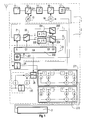
- Fig. 1 ein Blockschaltbild für einen Empfänger mit direkter Quadratur-Abtastung.
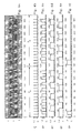
- Fig. 2 Abtastimpulsfolge und diverse Schaltsignal-Zeitdiagramme für achtfache Überabtastung eines Eingangssignals in einem Bitintervall von 158 Grundtakten und periodischer Fortsetzung der Abtastimpulse nach jedem Bitintervall.
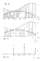
- Fig. 3a Abtastwerte nach Abtastung.
- Fig. 3b Abtastwerte nach Interpolation.
- Fig. 3c Abtastwerte nach Mittelung.
- Fig. 4 Abtastimpulse und diverse Schaltsignal-Zeitdiagramme für achtfache Überabtastung eines Eingangssignals in einem Bitintervall von 158 Grundtakten und periodischer Fortsetzung der Abtastimpulse nach 159 bzw. 155 Grundtakten.
- Fig. 1 is a block diagram for a receiver with direct quadrature scanning.
- Fig. 2 sampling pulse sequence and various switching signal timing diagrams for eight times oversampling an input signal in a bit interval of 158 basic clocks and periodic continuation of the sampling pulses after each bit interval.
- Fig. 3a samples after sampling.
- 3b samples after interpolation.
- 3c samples after averaging.
- Fig. 4 sampling pulses and various switching signal timing diagrams for eight times oversampling an input signal in a bit interval of 158 basic clocks and periodic continuation of the scanning pulses after 159 or 155 basic clocks.
Bei den folgenden Ausführungsbeispielen wird von binärcodierten Signalen, denen eine Bitfrequenz fb = 270,833 KHz (= 13 MHz/48) zugrundeliegt und die auf einen HF-Träger mittels Winkelmodulation aufmoduliert werden, ausgegangen. Fig. 1 zeigt in schematischer Darstellung einen Funkempfänger, welcher aus einem HF-Teil 1, einem Quadraturteil 2 und einer Anordnung zur digitalen Signalverarbeitung 3 besteht.In the following exemplary embodiments, binary-coded signals are used which are based on a bit frequency f b = 270.833 KHz (= 13 MHz / 48) and which are modulated onto an RF carrier by means of angle modulation. Fig. 1 shows a schematic representation of a radio receiver, which consists of an
Im HF-Teil 1 wird ein empfangenes Signal frequenzselektiert und auf eine Trägerfrequenz umgesetzt. Hierzu wird das von einer HF-Empfangsstufe 11 empfangene Signal mittels eines ersten ZF-Mischers 12, welchem von einem ersten ZF-Oszillator 13 eine erste variable ZF-Mischfrequenz fzf1 zugeführt ist, auf eine erste Zwischenfrequenz ZF1 heruntergemischt. Das auf diese erste Zwischenfrequenz heruntergemischte Eingangssignal wird in einem ersten ZF-Verstärker 14 bandpaßgefiltert und verstärkt und einem zweiten ZF-Mischer 15 zugeführt, in welchem mittels einer von einem zweiten ZF-Oszillator 16 zugeführten zweiten Zwischenfrequenz das Eingangssignal auf eine zweite Zwischenfrequenz ZF2 herabgemischt wird. In einem zweiten ZF-Verstärker 17 wird diese zweite Zwischenfrequenz ZF2 wiederum bandpaßgefiltert und verstärkt.In the
Die zweite Zwischenfrequenz ZF2 ist im Quadraturteil 2 einem Analog/Digital-Umsetzer 21 zugeführt. Dieser Analog/Digital-Umsetzer 21 wird von einem zentralen Taktgeber 20 mittels Taktimpulsen fi gesteuert. Bei diesem Ausführungsbeispiel wurde die zweite Zwischenfrequenz fZF2 so gewählt, daß sie einem ganzzahligen Vielfachen der halben Bittaktfrequenz fb entspricht. Als ganzzahliges Verhältnis von zweiter Oszillatorfrequenz fZF2 und halben Bittakt fb wurde der Wert 79 gewählt. Hieraus ergibt sich eine zweite Zwischenfrequenz von 10,6979166 MHz, welche den Vorteil bietet, daß sich diese Zwischenfrequenz nur sehr gering von der im Rundfunkbereich verwendeten Zwischenfrequenz von 10,7 MHz unterscheidet. Dies bietet den Vorteil, daß für diese gewählte Zwischenfrequenz fZF2 handelsübliche Filter eingesetzt werden können.The second intermediate frequency ZF2 is fed to an analog /
In einer zentralen Taktsteuerung 20 ist ein Taktgeber 201 angeordnet, welcher einen Grundtakt von einem Viertel der Wellenlänge der zweiten Zwischenfrequenz fZF2 erzeugt. Abweichungen vom vorgesehenen Frequenzverhältnis zwischen zweiter Zwischenfrequenz ZF2 und dem Grundtakt wirken sich wie eine Frequenzverstimmung aus. Bei entsprechend ausgelegter nachgeschalteter Signalverarbeitung können solche Frequenzverstimmungen, die klein sind zur Bandbreite des Signals, toleriert werden. Günstiger ist es aber, solche Frequenzverstimmungen von vornherein auszu schließen. Besonders vorteilhaft ist es, auch die Mischfrequenz des zweiten ZF-Oszillators 16 aus dem Taktgeber 201 abzuleiten. Dadurch kann das Frequenzverhältnis von zweiter Zwischenfrequenz ZF2 und Grundtakt unabhängig von äußeren Einflüssen starr festgelegt werden.A
In diesem Ausführungsbeispiel entsprechen 158 Grundtakte genau einem Bittakt der Bitfrequenz fb. Dieser Grundtakt ist einem Zählwerk 202 zugeführt. Dieses Zählwerk 202 erzeugt bei jedem neunten Grundtakt den Abtastimpuls fi. Hierdurch liegen zwei benachbarte Abtastwerte genau 2 Wellenlängen der zweiten Zwischenfrequenz ZF2 auseinander. Insgesamt erzeugt das Zählwerk innerhalb eines Bittaktes genau siebzehn solcher äquidistant aufeinanderfolgender Abtastimpulse. Diese siebzehn aufeinanderfolgenden Abtastwerte bilden somit eine Gruppe von äquidistanten Abtastwerten. Ein beim 153. Grundtakt eventuell möglicher Abtastimpuls wird unterdrückt, so daß in jedem Bittakt auf diese Weise genau neun Abtastwerte für die Normalkomponente und acht Abtastwerte für die Quadraturkomponente erhalten werden. Nach jeweils 158 Grundtakten wird das Zählwerk zurückgestellt und mit der Takterzeugung der Abtastimpulse fi wird wie vorstehend beschrieben wieder neu begonnen. Auf diese Weise setzt sich die Abfolge der erzeugten Abtastimpulse fi nach jedem 158. Grundtakt periodisch fort.In this exemplary embodiment, 158 basic clock cycles correspond to exactly one bit cycle of the bit frequency f b . This basic cycle is fed to a
Zwischen dem letzten Abtastwert einer Gruppe von Abtastwerten und dem ersten Abtastwert einer folgenden Gruppe von Abtastwerten liegen genau 14 Grundtakte. Die Gruppen folgen somit in einem Abstand von jeweils 14 Grundtakten aufeinander. In diesem Ausführungsbeispiel ist der Gruppenabstand größer gewählt als der Abstand zweier aufeinanderfolgender Abtastwerte innerhalb einer Gruppe. Einen entsprechend schnellen Analog/Digital-Umsetzer vorausge setzt kann der Gruppenabstand jedoch auch kleiner als der Abstand zweier aufeinanderfolgender Abtastwerte einer Gruppe gewählt sein.There are exactly 14 basic clocks between the last sample of a group of samples and the first sample of a subsequent group of samples. The groups follow one another at a distance of 14 basic cycles. In this exemplary embodiment, the group distance is chosen to be larger than the distance between two successive samples within a group. A correspondingly fast analog / digital converter is required however, the group distance can also be set to be smaller than the distance between two successive samples of a group.
Die technische Realisierung von Zählwerken ist dem Fachmann auf dem Gebiet der Digital-Elektronik geläufig. Eine der möglichen Realisierungen eines solchen Zählwerks kann beispielsweise dem Kapitel 10.7 "Systematischer Entwirrung von Schaltwerken" des Buches "Halbleiterschaltungstechnik", U. Tietze, Ch. Schenk, Springer Verlag Berlin, 8. Auflage, Seite 259 bis Seite 268 entnommen werden. Im folgenden wird daher auf die technische Realisierung des Zählwerks 201 nicht näher eingegangen. Stattdessen werden in noch im einzelnen näher erläuterten Figuren Zeit-Spannungsdiagramme für die einzelnen Schaltsignalausgänge des Zählwerks 201 angegeben, um das Zählwerk 201 zu beschreiben.The technical implementation of counters is familiar to the person skilled in the field of digital electronics. One of the possible implementations of such a counter can be found, for example, in chapter 10.7 "Systematic detangling of switching mechanisms" of the book "Semiconductor circuit technology", U. Tietze, Ch. Schenk, Springer Verlag Berlin, 8th edition, page 259 to page 268. Therefore, the technical implementation of the
In Fig. 2a ist eine unmodulierte Trägerschwingung fc dargestellt, wobei im unteren Teil der Fig. 2a eine Zeitachse aufgetragen ist, bei der jeder Grundtakt durch einen Strich der Zeitachse dargestellt ist. In Fig. 2b sind die vom Zählwerk 201 erzeugten Abtastimpulse fi, beginnend beim Grundtakt 0, dargestellt. Deutlich ist die Lücke zwischen dem auf den 144. Grundtakt des ersten Bittakts entfallenden siebzehnten Abtastimpuls und den nächsten auf den ersten Grundtakt des nächsten Bittakts (= 158. Grundtakt) fallenden Abtastimpuls fi zu sehen. Da, wie bereits beschrieben, der zeitliche Abstand der Abtastimpulse fi so gewählt ist, daß dieser Abstand genau 2 Wellenlängen der zweiten Zwischenfrequenz ZF2 entspricht, erhält man durch diese Abtastimpulse abwechselnd Abtastwerte der Normal- und der Quadraturkomponente. Die abwechselnd aufeinanderfolgenden Abtastwerte einer Bittaktperiode der Normal- und der Quadraturkomponenten wer den durch einen in der Zeichnung symbolisch als Umschalter dargestellten Komponentenverteiler 22 wechselweise einem ersten Signalzweig zur Verarbeitung der Normalkomponente und einem zweiten Signalzweig zur Verarbeitung der Quadraturkomponente zugeordnet. Ein entsprechendes Schaltsignal Q1 zur Steuerung des Komponentenverteilers 22 wird ebenfalls von dem Zählwerk 202 drzeugt. Der Komponentenverteiler 22 ist so aufgebaut, daß er bei einem niedrigen Spannungspegel (Low-Signal) an einem Schalteingang der gerade an einem Eingang anliegende Abtastwert dem ersten Signalzweig für die Bearbeitung der Normalkomponente zuführt und bei einem Schaltsignal mit hohem Spannungspegel (High-Signal) den gerade anliegenden Abtastwert dem zweiten Verarbeitungszweig zur Verarbeitung der Quadraturkomponenten weiterleitet. Der Spannungspegelverlauf des den Komponentenverteiler 22 steuernden Schaltsignals Q1 ist in Fig. 2c dargestellt. Deutlich ist zu sehen, daß das Schaltsignal Q1, beginnend beim 0. Grundtakt, mit Low-Pegel wechselweise alle neun Grundtakte seinen Spannungspegel von Low auf High und umgekehrt wechselt. Mit Beginn des nächsten Bittaktes, im Ausführungsbeispiel und in der Fig. 2a dem Grundtakt Nummer 158, entspricht der Signalverlauf des Schaltsignals Q1 dem im vorherigen Bittakt.FIG. 2a shows an unmodulated carrier vibration f c , a time axis being plotted in the lower part of FIG. 2a, in which each basic cycle is represented by a dash of the time axis. 2b shows the sampling pulses f i generated by the
Da der Abstand zwischen zwei Abtastwerten der Normalkomponente bzw. Abtastwerten der Quadraturkomponente auf diese Weise einem ungradzahligen Vielfachen der halben Wellenlänge der zweiten Zwischenfrequenz fzf2 entsprechen, muß jeder zweite Abtastwert der Normalkomponente und jeder zweite Abtastwert der Quadraturkomponente invertiert werden. Hierzu ist in jedem Signalzweig jeweils ein Vorzeicheninvertierer 231, 232 und ein Umschalter 233, 234 vorgesehen. Diese Umschalter 233, 234 sind so aufgebaut, daß bei einem Low-Pegel an ihrem Schaltein gang die Abtastwerte des jeweiligen Verarbeitungszweiges direkt durchgeschaltet werden, während bei einem High-Pegel an ihren Schalteingängen die Abtastwerte der Vorzeicheninvertierer 231, 232 weitergegeben werden. Der Verlauf eines zweiten Schaltsignals Q2, welches den ersten Umschalter 233 steuert, ist in Fig. 2d und der Verlust eines dritten Schaltsignals Q3, das den Schaltzustand des zweiten Umschalters 234 steuert, ist in Fig. 2e wiedergegeben. Die ebenfalls von dem Zählwerk 202 erzeugten zweiten und dritten Schaltsignale Q2, Q3 sind so gewählt, daß wechselweise in jedem Signalzweig jeweils der Abtastwert bzw. bei jedem zweiten Abtastwert der invertierte Abtastwert weitergeleitet wird. In Fig. 3a sind die nach der Vorzeichenumkehr erhaltenen Abtastwerte eines modulierten Signals symbolisch dargestellt, wobei die Normalkomponenten an ihrer Spitze ein x und die Quadraturkomponenten an ihrer Spitze ein o tragen. Obwohl Normal- und Quadraturkomponente in getrennten Signalzweigen verarbeitet werden, sind sie in der Fig. 3 stets zusammen dargestellt, um ihre zeitliche Zuordnung zueinander zu verdeutlichen. Aus der Fig. 3a ist ersichtlich, daß ein Abtastwert der Quadraturkomponente zeitlich gesteuert jeweils in der Mitte zwischen zwei Abtastwerten der Normalkomponente liegt.Since the distance between two samples of the normal component or samples of the quadrature component in this way corresponds to an odd multiple of half the wavelength of the second intermediate frequency f zf2 , every second sample of the normal component and every second sample of the quadrature component must be inverted. For this purpose, a
In einem Interpolator 25 wird die Normalkomponente gefiltert. Da die zur Interpolation herangezogenen Abtastwerte äquidistant und eng benachbart sind, vereinfacht sich dadurch der Aufbau des Interpolators und das Interpolationsergebnis wird verbessert. Im Ausführungsbeispiel wird ein linearer Interpolator verwendet, welcher jeweils aus zwei aufeinanderfolgenden Abtastwerten einen Interpolationswert bildet.The normal component is filtered in an interpolator 25. Since the sampling values used for the interpolation are equidistant and closely adjacent, the structure of the interpolator is simplified and the interpolation result is improved. In the exemplary embodiment, a linear interpolator is used, which in each case forms an interpolation value from two successive sample values.
Im Interpolator 25 wird jeweils der letzte Abtastwert in einem Register zwischengespeichert. Der zwischengespeicherte Abtastwert und der gerade am Eingang anliegende Abtastwert werden halbiert, beispielsweise durch eine Verschiebung des Bitmusters um eine Stelle nach links, und dann addiert. Der auf diese Weise interpolierte Wert entspricht in guter Näherung einem Abtastwert, den man in der Mitte zwischen den zwei letzten dem Interpolator zugeführten Abtastwerten erhalten hätte. Auf diese Weise ist der interpolierte Abtastwert der Normalkomponente und der Abtastwert der Quadraturkomponente, der zeitlich zwischen den beiden letzten, dem Interpolator 25 zugeführten Abtastwerten der Normalkomponente jeweils abgetastet wurde, als zeitgleich abgetastet zu betrachten.The last sample value is in each case in the interpolator 25 cached in a register. The temporarily stored sample value and the sample value currently present at the input are halved, for example by shifting the bit pattern to the left by one position, and then added. The value interpolated in this way corresponds to a good approximation to a sample value which would have been obtained in the middle between the two last sample values supplied to the interpolator. In this way, the interpolated sample of the normal component and the sample of the quadrature component, which was sampled in time between the two last samples of the normal component fed to the interpolator 25, are to be regarded as sampled at the same time.
Da das Ergebnis des Interpolators 25 immer nur nach Bearbeitung der letzten beiden zugeführten Abtastwerte erhalten wird, muß, um die Zeitgleichheit zwischen interpoliertem Abtastwert und zugehöriger Quadraturkomponente bei der weiteren Bearbeitung zu erzielen, der zugehörige Abtastwert der Quadraturkomponente durch ein Verzögerungsglied 24 zeitlich verzögert werden. Diese zeitliche Verzögerung entspricht genau dem Abstand zwischen zwei regulär aufeinanderfolgenden Abtastimpulsen fi, im Ausführungsbeispiel also 9 Grundtakten. Durch die Interpolation werden aus den neun Abtastwerten der Normalkomponente eines Bittakts acht interpolierte Abtastwerte gebildet (siehe Fig. 3b). Durch einen von einem vierten Steuerungssignal Q4 gesteuerten Ausschalter 26 wird verhindert, daß ein nach dem neunten Abtastwert gebildeter interpolierter Wert weitergeleitet wird (siehe Signalverlauf des Schaltsignals Q4 in Fig. 2e). Wegen der Verzögerung der Ausgangswerte des Interpolators durch die Interpolation wird das Schaltsignal Q4 um eben diese Verzögerung zeitlich verzögert erzeugt.Since the result of the interpolator 25 is always obtained only after processing the last two supplied samples, in order to achieve the same time between the interpolated sample and the associated quadrature component during further processing, the associated sample value of the quadrature component must be delayed by a
Fig. 3b zeigt, wie aus den neun Abtastwerten der Normalkomponente acht interpolierte Abtastwerte der Normalkomponente erhalten werden.3b shows how eight interpolated samples of the normal component are obtained from the nine samples of the normal component.
Die acht interpolierten Abtastwerte der Normalkomponente und die acht Abtastwerte der Quadraturkomponente sind jeweils für sich einem Mittelungsfilter 271, 2f2 zugeführt. In den Filtern 271, 272 wird aus den jeweiligen acht Abtastwerten jeweils ein einziger Wert für die Normalkomponente bzw. die Quadraturkomponente gebildet. Durch die achtfache Überabtastung wird auf diese Weise das Quantisierungsrauschen des Analog/Digital-Umsetzers um neun dB verringert. Auf diese Weise erhält man für jeden Bittakt jeweils genau einen Wert für die Normalkomponente und die Quadraturkomponente. Durch den äquidistanten Abstand der acht Abtastwerte vereinfacht sich auch der Aufbau des Mittelungsfilters. Im Ausführungsbeispiel werden die jeweils mit einem Faktor von 1/8 multiplizierten Abtastwerte eines Bittakts aufsummiert, um den Mittelwert der jeweiligen Normal- bzw. Quadraturkomponente eines Bittakts zu erhalten.The eight interpolated samples of the normal component and the eight samples of the quadrature component are each fed to an averaging
Fig. 3c zeigt, wie aus jeweils acht Abtastwerten ein einziger gemittelter Abtastwert, jeweils zum Ende eines Bittakts, erzeugt wird.3c shows how a single averaged sample value is generated from eight sample values in each case, at the end of a bit clock.
Wenn die Anzahl der auf einen Bittakt entfallenden Grundtakte eine ohne Rest durch vier teilbare Zahl ist, dann ist das Ergebnis der Mittelung aufeinanderfolgender Bittakte vorzeichenrichtig und die auf vorstehende Weise gewonnenen Quadraturkomponenten können ohne Überarbeitung zur digitalen Signalbearbeitung weitergereicht werden. Verbleibt jedoch, wie im vorliegenden Fall, beim Dividieren der Grundtakte pro Bittakt ein Rest von zwei, so müssen die auf vorstehende Weise gewonnenen Quadraturkompo nenten für jeden zweiten Bittakt invertiert werden. Dies kann aber in vorteilhafter Weise auch dadurch realisiert werden, daß das Zählwerk 201 in jedem zweiten Bittakt die Steuersignale zum Umschalten der Umschalter 231, 232 um 180 Grad phasenverschoben erzeugt (siehe insbesondere den Verlauf der Schaltsignale Q2, Q3 während der Grundtakte 158 bis 15), so daß in jedem zweiten Bitintervall jeder Abtastwert, der nicht invertiert wurde, nunmehr invertiert wird, und jeder Abtastwert, der im ersten Bitintervall invertiert wurde, nunmehr nicht invertiert wird. Auf diese Weise setzen sich die Schaltsignale Q2 und Q3 erst nach jedem zweiten Bitintervall periodisch fort, während die Schaltsignale Q1 und Q4 sich jeweils nach jedem Bitintervall periodisch fortsetzen.If the number of basic clocks per bit clock is a number divisible without a remainder by four, the result of averaging successive bit clocks is correct and the quadrature components obtained in the above manner can be passed on for digital signal processing without revision. If, however, as in the present case, there remains a remainder of two when dividing the basic clocks per bit clock, then the quadrature compo obtained in the above manner must nents are inverted for every second bit clock. However, this can also be advantageously achieved in that the
Ist die Anzahl der Abtastimpulse pro Bittakt so gewählt, daß die Zahl der Abtastimpulse dividiert durch vier einen Rest von eins ergibt, so rotieren die Quadraturkomponenten von Bittakt zu Bittakt um jeweils 90 Grad. Der Abtastwert der Normalkomponente 1 wird im zweiten Bittakt zur Quadraturkomponente Q, im dritten Bittakt zur invertierten Normalkomponente -I und im vierten Bittakt zur invertierten Quadraturkomponente -Q. Das Gleiche gilt entsprechend für die Quadraturkomponente Q. Ist die Anzahl der Grundtakte pro Bittakt so gewählt, daß sie durch vier geteilt einen Rest von drei ergibt, so eilen die Quadraturkomponenten von Bittakt zu Bittakt um 90 Grad in der Phase nach.If the number of sampling pulses per bit clock is chosen such that the number of sampling pulses divided by four results in a remainder of one, the quadrature components rotate by 90 degrees from bit clock to bit clock. The sample value of the
Wenn im Sender eine nichtlineare Winkelmodulation, wie z.B. eine als gaussian minimum shift keying (GMSK) bekannte Modulationsart oder eine als generalized tamed frequenzy modulation (GTFM) bekannte Modulationsart gewählt sind, dann kann durch diesen Rotationseffekt der Aufwand, der zur Signalentzerrung im digitalen Signalver arbeitungsteil 3 zu betreiben ist sogar verringert werden. Bei solchen Modulationsarten braucht nicht mehr die komplizierte Struktur einer nichtlinearen Winkelmodulation berücksichtigt zu werden, sondern die Entzerrung kann sich darauf beschränken, als sei beim Senden eine lineare Amplitudenmodulation verwendet worden. Zur Entzerrung und Demodulation sind im digitalen Signalverarbeitungsteil 3 dadurch nur noch reelle Zahlenwerte zu verarbeiten.If a nonlinear angle modulation, such as a type of modulation known as gaussian minimum shift keying (GMSK) or a type of modulation known as generalized tamed frequency modulation (GTFM), is selected in the transmitter, then this rotation effect can reduce the effort required for signal equalization in digital signal
Im folgenden wird kurz ein Ausführungsbeispiel für eine solche Rotation der Quadraturkomponenten beschrieben. Ausgehend von der gleichen Bitfrequenz fb = 270,833 KHz wird die Anzahl der Grundtakte pro Bitintervall Ta zu 159 gewählt. Bei dieser Zahl bleibt bei der Division durch vier ein Rest von drei, wodurch die Bedingung für die Rotation erfüllt ist. Als zweite Zwischenfrequenz ZF2 ergibt sich somit 159*(fb/4) = 10,76562 MHz, also eine Frequenz, die immer noch nahe an 10,7 MHz liegt. Unter Beibehaltung der Abstände der Abtastimpulse fi werden von dem Zählwerk 201 die gleichen Schaltsignale Q1, Q2, Q3 und Q4 erzeugt, wobei lediglich nach jedem 158. Grundtakt ein zusätzlicher 159. Grundtakt pro Bitintervall eingefügt wird, bei dem alle Schaltsignale Q1, Q2, Q3 den gleichen Signalzustand beibehalten wie im vorhergegangenen Grundtakt 158. Wegen der Rotation bleiben die Schaltsignale in den aufeinanderfolgenden Bitintervallen gleich und wiederholen sich periodisch nach jedem Bitintervall Ta.An exemplary embodiment for such a rotation of the quadrature components is briefly described below. Starting from the same bit frequency f b = 270.833 KHz, the number of basic clock cycles per bit interval T a is chosen to be 159. This number leaves a remainder of three when divided by four, which fulfills the condition for rotation. The second intermediate frequency ZF2 thus results in 159 * (f b / 4) = 10.76562 MHz, that is to say a frequency which is still close to 10.7 MHz. While maintaining the intervals of the scanning pulses fi, the
Werden für die Signalverarbeitung dennoch die phasenrichtigen Quadraturkomponenten benötigt, so kann bei einer Ausführungsform, bei der die Anzahl der Grundtakte pro Bitintervall dividiert durch vier einen ungeraden Rest ergibt, durch ein bittaktweises Vertauschen bzw. und/oder Invertieren der Komponenten diese Rotation rückgängig ge macht werden. Dies kann beispielsweise durch eine Nachbearbeitung der Quadraturkomponenten erfolgen, indem die Quadraturkomponenten einem nicht dargestellten Vertauschungsschalter zugeführt sind, welcher in jedem zweiten Bitintervall Ta Normalkomponente und Quadraturkomponente miteinander vertauscht. Die noch benötigten Invertierungen können schon durch entsprechende Ansteuerung der Umschalter 233, 234 vorgenommen werden.If the in-phase quadrature components are nevertheless required for signal processing, in one embodiment in which the number of basic clocks per bit interval divided by four results in an odd remainder, this rotation can be reversed by bit-by-bit swapping or and / or inverting the components be made. This can be done, for example, by postprocessing the quadrature components by feeding the quadrature components to a swap switch, not shown, which interchanges the normal component and quadrature component with one another in every second bit interval T a . The inversions still required can already be carried out by appropriately controlling the changeover switches 233, 234.
In einem weiteren, in Fig. 4 dargestellten, Ausführungsbeispiel ist wiederum, wie im ersten Ausführungsbeispiel, die zweite Zwischenfrequenz ZF2 so gewählt, daß ein Bitintervall 158 Grundtakten entspricht. Dargestellt sind die zeitliche Lage der Abtastimpulse und Schaltsignale für vier aufeinanderfolgende Bitintervalle. Die Abtastimpulse fi und Schaltsignale des ersten Bitintervalls (= Grundtakt 0 bis 158 in Fig. 4) entsprechen den Abtastimpulsen und Schaltsignalen während des ersten Bitintervalls im ersten Ausführungsbeispiel. Die periodische Fortsetzung der Abtastimpulse und der zugehörigen Schaltsignale wird jedoch in diesem Ausführungsbeispiel in drei aufeinanderfolgenden Bitintervallen um jeweils einen Grundtakt verzögert und in einem darauffolgenden vierten Bitintervall um drei Grundtakte verkürzt. Hierdurch ist der erste Abtastimpuls des zweiten Bitintervalls (= Grundtakte 158 bis 316 in Fig. 4) nicht wie in den vorangegangenen Ausführungsbeispielen auf den ersten, sondern auf den zweiten Grundtakt des zweiten Bitintervalls (= Grundtakt 159 in Fig. 4b) gelegt. Aus Fig. 4a ist ersichtlich, daß hierdurch gegenüber dem ersten Ausführungsbeispiel (siehe Fig. 2a) um eine Viertelperiode der Trägerfrequenz später abgetastet wird. Hierdurch wird bei der Abtastung mit dem ersten Abtastimpuls im zweiten Bitintervall die invertierte Quadraturkomponente erhalten. Der zweite Abtastwert im zweiten Bitintervall ergibt einen Abtastwert für die Normalkomponente. Entsprechendes gilt für die anderen Abtastwerte des zweiten Bitintervalls.In a further exemplary embodiment shown in FIG. 4, the second intermediate frequency ZF2 is again selected such that a bit interval corresponds to 158 basic clocks, as in the first exemplary embodiment. The position of the sampling pulses and switching signals for four successive bit intervals are shown. The sampling pulses f i and switching signals of the first bit interval (=
Im dritten Bitintervall (= Grundtakt 316 bis 474 in Fig. 4b′) werden wiederum die Abtastimpulsfolge und die zugehörigen Schaltsignale um einen Grundtakt verzögert fortgesetzt. Der erste Abtastimpuls des dritten Bitintervalls fällt somit auf den dritten Grundtakt des dritten Bitintervalls (= Grundtakt 318 in Fig. 4b′). In diesem Fall ergibt sich aus der Fig. 4a′, daß der erste Abtastwert des dritten Abtastintervalls der invertierten Normalkomponente und der zweite Abtastwert des dritten Abtastintervalls einem Abtastwert der Quadraturkomponente entsprechen. Ebenso wird die periodische Folge der Abtastimpulse auch im vierten Bitintervall (= Grundtakt 474 bis 632) wieder um einen Grundtakt verzögert fortgesetzt. Der erste Abtastimpuls des vierten Abtastintervalls entspricht somit dem Grundtakt 477. Der durch den ersten Abtastimpuls im vierten Bitintervall erhaltene Abtastwert entspricht somit dem Abtastwert einer Quadraturkomponente und der zweite Abtastwert des vierten Bitintervalls einem invertierten Abtastwert der Quadraturkomponente.In the third bit interval (= basic clock 316 to 474 in Fig. 4b '), the scanning pulse sequence and the associated switching signals are again delayed by a basic clock. The first sampling pulse of the third bit interval thus falls on the third basic clock of the third bit interval (= basic clock 318 in Fig. 4b '). In this case, it follows from Fig. 4a 'that the first sample of the third sampling interval of the inverted normal component and the second sample of the third sampling interval correspond to a sample of the quadrature component. Likewise, the periodic sequence of the sampling pulses is again delayed by a basic clock in the fourth bit interval (= basic clock 474 to 632). The first sample pulse of the fourth sample interval thus corresponds to the basic clock 477. The sample value obtained by the first sample pulse in the fourth bit interval thus corresponds to the sample value of a quadrature component and the second sample value of the fourth bit interval corresponds to an inverted sample value of the quadrature component.
In den ersten drei Bitintervallen ist die periodische Fortsetzung der Abtastimpulse und der Schaltsignale Q1, Q2, Q3 um jeweils einen Grundtakt länger als die Anzahl der Grundtakte pro Intervall, beträgt also in diesem Ausführungsbeispiel dreimal hintereinander jeweils 159 Grundtakte. Der zeitliche Abstand zwischen dem ersten Abtastwert des vierten Bitintervalls und dem ersten Abtastwert des nächsten Bitintervalls ist bei diesem Ausführungsbeispiel hingegen um drei Grundtakte verkürzt und beträgt demgemäß nur 155 Grundtakte. Auf diese Weise liegt der erste Abtastwert des fünften Bitintervalls beim Grundtakt 632. Der Abstand zwischen dem ersten Abtastimpuls des ersten Bitintervalls und des ersten Abtastimpulses des fünften Bitintervalls entspricht auf diese Weise genau vier Bitintervallen (= 632 = das Vierfache von 158 Grundtakten). Auf diese Weise erhält man durch den ersten Abtastimpuls des fünften Bitintervalls wieder einen Abtastwert der Normalkomponente. Der Verlauf der Abtastimpulse und der Signalverlauf des fünften Abtastintervalls entspricht nunmehr wieder dem ersten Abtastintervall.In the first three bit intervals, the periodic continuation of the scanning pulses and the switching signals Q1, Q2, Q3 is in each case one basic cycle longer than the number of basic cycles per interval, so in this exemplary embodiment it is 159 basic cycles three times in succession. In contrast, the time interval between the first sample value of the fourth bit interval and the first sample value of the next bit interval is shortened by three basic clock cycles in this exemplary embodiment and is accordingly only 155 basic clock cycles. In this way the first sample of the fifth bit interval lies at the basic clock 632. The distance between the first sample pulse of the first bit interval and the first sample pulse of the fifth bit interval thus corresponds to exactly four bit intervals (= 632 = four times 158 base clocks). In this way, a sample of the normal component is obtained again by the first sampling pulse of the fifth bit interval. The course of the sampling pulses and the signal course of the fifth sampling interval now again corresponds to the first sampling interval.
Durch die beschriebene Abfolge der Abtastimpulse sind die Abtastimpulse in aufeinanderfolgenden Bitintervallen Ta jeweils um eine Viertelperiode der zweiten Zwischenfrequenz ZF2 verschoben. Dadurch werden jedem der beiden Zweige abwechselnd Abtastwerte der I- und Q-Komponenten zugeführt. I- und Q Komponenten werden abwechselnd interpoliert. Nach jeweils vier Bitintervallen findet durch eine um drei Grundtakte verkürzte Aufeinanderfolge der Abtastimpulse ein Taktausgleich statt, so daß im Mittel die Anzahl der Grundtakte pro Bitintervall und die Anzahl von Ausgangswerten der Quadratur-Signalerzeugung im Vergleich zum ersten Ausführungsbeispiel gleich sind.Due to the described sequence of sampling pulses, the sampling pulses are shifted in successive bit intervals T a by a quarter period of the second intermediate frequency ZF2. As a result, samples of the I and Q components are alternately fed to each of the two branches. I and Q components are interpolated alternately. After every four bit intervals there is a clock equalization due to a succession of the sampling pulses shortened by three basic clocks, so that on average the number of basic clocks per bit interval and the number of output values of the quadrature signal generation are the same as in the first exemplary embodiment.
Dieses Ausführungsbeispiel bietet den Vorteil, daß der Verlauf der Schaltsignale Q1, Q2, Q3 in allen vier Bitintervallen gleich bleibt. Dies vereinfacht den Aufbau des Zählwerks. Das Zählwerk wird jeweils dreimal hintereinander nach 159 Grundtakten zurückgesetzt und nach diesen drei längeren Grundtakten einmal bereits nach 155 Grundtakten zurückgesetzt.This embodiment offers the advantage that the course of the switching signals Q1, Q2, Q3 remains the same in all four bit intervals. This simplifies the construction of the counter. The counter is reset three times in a row after 159 basic cycles and after these three longer basic cycles once already after 155 basic cycles.
Auf diese Weise können auch bei Bitintervallen, deren Anzahl der Grundtakte pro Bitintervall eine gerade Zahl ist, von Bitintervall zu Bitintervall rotierende Abtastwerte erhalten werden. Sinngemäß läßt sich diese Ausführungsform auch auf Ausführungen übertragen, bei denen die Anzahl der Grundtakte pro Bitintervall eine ungerade Zahl ist, und der dadurch auftretende Rotationseffekt der Abtastwerte rückgängig gemacht werden soll.In this way, even with bit intervals, the number of basic clocks per bit interval is an even number , rotating samples are obtained from bit interval to bit interval. Analogously, this embodiment can also be applied to versions in which the number of basic clock cycles per bit interval is an odd number, and the rotation effect of the sampling values that is caused thereby is to be reversed.
Claims (10)
dadurch gekennzeichnet,
daß eine Anzahl von äquidistanten Abtastzeitpunkten jeweils zu einer Gruppe zusammengefaßt sind und daß für den Abstand zwischen dem letzten Abtastzeitpunkt einer Gruppe und dem ersten Abtastzeitpunkt der folgenden Gruppe (Gruppenabstand) eine andere Zeitspanne gewählt ist als für den zeitlichen Abstand zweier aufeinanderfolgender Abtastzeitpunkte einer Gruppe.1. Receiver in which a normal component and a quadrature component of a signal modulated onto a carrier signal are obtained directly by sampling the carrier signal, the time of the sampling being determined by a sequence of sampling times,
characterized by
that a number of equidistant sampling times are combined to form a group and that a different period of time is selected for the distance between the last sampling time of a group and the first sampling time of the following group (group distance) than for the time interval between two successive sampling times of a group.
dadurch gekennzeichnet,
daß der Gruppenabstand von Gruppe zu Gruppe unterschiedlich gewählt ist.2. Receiver according to claim 1,
characterized by
that the group distance is selected differently from group to group.
dadurch gekennzeichnet,
daß der Gruppenabstand einem Vielfachen eines Viertels der Wellenlänge des Trägersignals entspricht.3. Receiver according to one of claims 1 or 2,
characterized by
that the group distance corresponds to a multiple of a quarter of the wavelength of the carrier signal.
dadurch gekennzeichnet,
daß der Abstand zwischen einem ersten Abtastzeitpunkt ei ner Gruppe und einem ersten Abtastzeitpunkt der nachfolgenden Gruppe (Gruppenlänge) gleich oder einem ganzzahligen Vielfachen der Bittaktrate des digitalen Signals gewählt ist.4. Receiver according to one of claims 1, 2 or 3, in which the modulated signal is based on a digital signal of a certain bit rate,
characterized by
that the distance between a first sampling time ei ner group and a first sampling time of the subsequent group (group length) is selected to be equal to or an integer multiple of the bit clock rate of the digital signal.
dadurch gekennzeichnet,
daß die Abtastzeitpunkte durch Abtastimpulse festgelegt sind, die von einem Zählwerk (202) erzeugt werden.5. Receiver according to one of claims 1, 2, 3 or 4,
characterized by
that the sampling times are determined by sampling pulses generated by a counter (202).
dadurch gekennzeichnet,
daß ein Komponentenverteiler (22) vorgesehen ist, welcher in Abhängigkeit eines Schaltsignals (Q1) die zu den einzelnen Abtastzeitpunkten gewonnenen Abtastwerte einem Signalzweig zur Verarbeitung der Normalkomponente und einem Signalzweig zur Verarbeitung der Quadraturkomponente zuteilt.6. Receiver according to one of claims 1, 2, 3, 4 or 5,
characterized by
that a component distributor (22) is provided which, depending on a switching signal (Q1), allocates the samples obtained at the individual sampling times to a signal branch for processing the normal component and a signal branch for processing the quadrature component.
dadurch gekennzeichnet,
daß mindestens ein Vorzeicheninvertierer (231) vorgesehen ist, welchem die Abtastwerte zugeführt sind und daß ein Umschalter (233) vorgesehen ist, an dessen einen Eingang der Abtastwert und an dessen zweiten Eingang der durch den Vorzeicheninvertierer (231) invertierte Abtastwert zugeführt sind.7. Receiver according to one of claims 1, 2, 3, 4, 5 or 6,
characterized by
that at least one sign inverter (231) is provided, to which the samples are supplied and that a changeover switch (233) is provided, at the one input of which the sample value and at the second input of which the sample value inverted by the sign inverter (231) are supplied.
dadurch gekennzeichnet,
daß in mindestens einem der beiden Signalzweige ein Interpolator (25) vorgesehen ist.8. Receiver according to one of claims 1, 2, 3, 4, 5, 6 or 7,
characterized by
that an interpolator (25) is provided in at least one of the two signal branches.
dadurch gekennzeichnet,
daß in den beiden Signalzweigen Mittelungsfilter (271, 272) vorgesehen sind.9. Receiver according to one of claims 1, 2, 3, 4, 5, 6, 7 or 8,
characterized by
that averaging filters (271, 272) are provided in the two signal branches.
dadurch gekennzeichnet,
daß Abtastzeitpunkte und eine zur Gewinnung der Trägerfrequenz vorgesehene Mischfrequenz aus einer einzigen Oszillatorfrequenz abgeleitet werden.10. Receiver according to one of claims 1, 2, 3 4, 5, 6, 7, 8 or 9,
characterized by
that sampling times and a mixing frequency provided for obtaining the carrier frequency are derived from a single oscillator frequency.
Applications Claiming Priority (2)
| Application Number | Priority Date | Filing Date | Title |
|---|---|---|---|
| DE3938126 | 1989-11-16 | ||
| DE3938126A DE3938126A1 (en) | 1989-11-16 | 1989-11-16 | RECEIVER WITH DIRECT SQUARE SAMPLE OF THE INPUT SIGNAL |
Publications (3)
| Publication Number | Publication Date |
|---|---|
| EP0428226A2 true EP0428226A2 (en) | 1991-05-22 |
| EP0428226A3 EP0428226A3 (en) | 1993-01-13 |
| EP0428226B1 EP0428226B1 (en) | 1996-09-04 |
Family
ID=6393664
Family Applications (1)
| Application Number | Title | Priority Date | Filing Date |
|---|---|---|---|
| EP90202997A Expired - Lifetime EP0428226B1 (en) | 1989-11-16 | 1990-11-13 | Receiver with direct quadrature sampling of the input signal |
Country Status (7)
| Country | Link |
|---|---|
| US (1) | US5142553A (en) |
| EP (1) | EP0428226B1 (en) |
| JP (1) | JP2991245B2 (en) |
| KR (1) | KR0176696B1 (en) |
| CA (1) | CA2029802C (en) |
| DE (2) | DE3938126A1 (en) |
| FI (1) | FI103159B (en) |
Cited By (3)
| Publication number | Priority date | Publication date | Assignee | Title |
|---|---|---|---|---|
| EP0458452A2 (en) * | 1990-05-25 | 1991-11-27 | Nokia Mobile Phones (U.K.) Limited | Quadrature demodulator |
| FR2691315A1 (en) * | 1992-05-15 | 1993-11-19 | France Telecom | Digital quadrature phase modulator-demodulator for telecommunications - has pairs of digital filters applying filtered signal or inverse signal to subtractor obtaining real and imaginary output components |
| WO1998006206A1 (en) * | 1996-08-07 | 1998-02-12 | Sat (Societe Anonyme De Telecommunications) | Demodulator with digital circuit for recovering carrier and rhythm |
Families Citing this family (22)
| Publication number | Priority date | Publication date | Assignee | Title |
|---|---|---|---|---|
| JP3003826B2 (en) * | 1992-12-11 | 2000-01-31 | 三菱電機株式会社 | Clock recovery circuit |
| US5375146A (en) * | 1993-05-06 | 1994-12-20 | Comsat Corporation | Digital frequency conversion and tuning scheme for microwave radio receivers and transmitters |
| US5410499A (en) * | 1994-03-31 | 1995-04-25 | The United States Of America As Represented By The Secretary Of The Navy | Phase shifter for directly sampled bandpass signals |
| JP3055085B2 (en) * | 1994-04-22 | 2000-06-19 | 株式会社アドバンテスト | Digital modulation analyzer |
| JPH07321862A (en) * | 1994-05-25 | 1995-12-08 | Matsushita Electric Ind Co Ltd | Digitally modulated wave demodulator |
| US5841814A (en) * | 1995-10-17 | 1998-11-24 | Paradyne Corporation | Sampling system for radio frequency receiver |
| US5937341A (en) | 1996-09-13 | 1999-08-10 | University Of Washington | Simplified high frequency tuner and tuning method |
| US6151354A (en) * | 1997-12-19 | 2000-11-21 | Rockwell Science Center | Multi-mode, multi-band, multi-user radio system architecture |
| FR2780590B1 (en) * | 1998-06-29 | 2000-10-06 | Sgs Thomson Microelectronics | QPSK DEMODULATOR WITH INTERMEDIATE FREQUENCY INPUT |
| CN1227881C (en) | 1999-10-04 | 2005-11-16 | 日本电气株式会社 | Demodulator for processing digital signal |
| DE10005497A1 (en) | 2000-02-08 | 2001-08-09 | Infineon Technologies Ag | Method and circuit arrangement for demodulating a quadrature amplitude or phase modulated signal |
| US7388931B1 (en) | 2002-06-12 | 2008-06-17 | Marvell International Ltd. | ADC architecture for wireless applications |
| US7272375B2 (en) | 2004-06-30 | 2007-09-18 | Silicon Laboratories Inc. | Integrated low-IF terrestrial audio broadcast receiver and associated method |
| GB0421930D0 (en) * | 2004-10-01 | 2004-11-03 | Nokia Corp | Signal receiver |
| US7714760B2 (en) * | 2008-06-27 | 2010-05-11 | Entropic Communications, Inc. | Apparatus and methods for direct quadrature sampling |
| GB0903157D0 (en) * | 2009-02-25 | 2009-04-08 | Innovation Res & Technology Pl | Demodulation mixing |
| EP2288041A3 (en) * | 2009-08-18 | 2013-04-24 | Gerald Youngblood | Direct conversion receiver |
| US9484968B2 (en) | 2012-10-12 | 2016-11-01 | Innoventure L.P. | Post conversion mixing |
| US9490944B2 (en) | 2012-10-12 | 2016-11-08 | Innoventure L.P. | Phase sector based RF signal acquisition |
| US9225368B2 (en) | 2012-10-12 | 2015-12-29 | Innoventure L.P. | Periodic time segment sequence based signal generation |
| US9264268B2 (en) | 2012-10-12 | 2016-02-16 | Innoventure L.P. | Periodic time segment sequence based decimation |
| US9484969B2 (en) | 2012-10-12 | 2016-11-01 | Innoventure L.P. | Delta-pi signal acquisition |
Citations (3)
| Publication number | Priority date | Publication date | Assignee | Title |
|---|---|---|---|---|
| US4079329A (en) * | 1976-11-11 | 1978-03-14 | Harris Corporation | Signal demodulator including data normalization |
| US4412302A (en) * | 1980-12-15 | 1983-10-25 | Rca Corporation | Digital phase demodulation and correlation |
| EP0350999A2 (en) * | 1988-07-09 | 1990-01-17 | Philips Patentverwaltung GmbH | Device to equalize and demodulate binary continuous phase modulated data signals with modulation index 0.5 |
Family Cites Families (5)
| Publication number | Priority date | Publication date | Assignee | Title |
|---|---|---|---|---|
| JPS5923945A (en) * | 1982-07-30 | 1984-02-07 | Toshiba Corp | Detecting system of radio line signal |
| US4733403A (en) * | 1986-05-12 | 1988-03-22 | Motorola, Inc. | Digital zero IF selectivity section |
| US4910752A (en) * | 1987-06-15 | 1990-03-20 | Motorola, Inc. | Low power digital receiver |
| US4779054A (en) * | 1987-08-17 | 1988-10-18 | General Electric Company | Digital inphase/quadrature product detector |
| DE3815055A1 (en) * | 1988-05-04 | 1989-11-16 | Standard Elektrik Lorenz Ag | SQUARE RECEIVER |
-
1989
- 1989-11-16 DE DE3938126A patent/DE3938126A1/en not_active Withdrawn
-
1990
- 1990-11-13 DE DE59010483T patent/DE59010483D1/en not_active Expired - Fee Related
- 1990-11-13 CA CA002029802A patent/CA2029802C/en not_active Expired - Fee Related
- 1990-11-13 EP EP90202997A patent/EP0428226B1/en not_active Expired - Lifetime
- 1990-11-13 US US07/613,346 patent/US5142553A/en not_active Expired - Fee Related
- 1990-11-13 FI FI905607A patent/FI103159B/en not_active IP Right Cessation
- 1990-11-15 KR KR1019900018461A patent/KR0176696B1/en not_active IP Right Cessation
- 1990-11-15 JP JP2311234A patent/JP2991245B2/en not_active Expired - Fee Related
Patent Citations (3)
| Publication number | Priority date | Publication date | Assignee | Title |
|---|---|---|---|---|
| US4079329A (en) * | 1976-11-11 | 1978-03-14 | Harris Corporation | Signal demodulator including data normalization |
| US4412302A (en) * | 1980-12-15 | 1983-10-25 | Rca Corporation | Digital phase demodulation and correlation |
| EP0350999A2 (en) * | 1988-07-09 | 1990-01-17 | Philips Patentverwaltung GmbH | Device to equalize and demodulate binary continuous phase modulated data signals with modulation index 0.5 |
Cited By (5)
| Publication number | Priority date | Publication date | Assignee | Title |
|---|---|---|---|---|
| EP0458452A2 (en) * | 1990-05-25 | 1991-11-27 | Nokia Mobile Phones (U.K.) Limited | Quadrature demodulator |
| EP0458452A3 (en) * | 1990-05-25 | 1991-12-18 | Nokia Mobile Phones (U.K.) Limited | Quadrature demodulator |
| FR2691315A1 (en) * | 1992-05-15 | 1993-11-19 | France Telecom | Digital quadrature phase modulator-demodulator for telecommunications - has pairs of digital filters applying filtered signal or inverse signal to subtractor obtaining real and imaginary output components |
| WO1998006206A1 (en) * | 1996-08-07 | 1998-02-12 | Sat (Societe Anonyme De Telecommunications) | Demodulator with digital circuit for recovering carrier and rhythm |
| FR2752348A1 (en) * | 1996-08-07 | 1998-02-13 | Telecommunications Sa | DEMODULATOR WITH DIGITAL CIRCUIT FOR CARRIER AND RHYTHM RECOVERY |
Also Published As
| Publication number | Publication date |
|---|---|
| FI905607A (en) | 1991-05-17 |
| FI103159B1 (en) | 1999-04-30 |
| EP0428226A3 (en) | 1993-01-13 |
| FI103159B (en) | 1999-04-30 |
| JPH03293843A (en) | 1991-12-25 |
| DE3938126A1 (en) | 1991-05-23 |
| CA2029802A1 (en) | 1991-05-17 |
| DE59010483D1 (en) | 1996-10-10 |
| KR910010931A (en) | 1991-06-29 |
| EP0428226B1 (en) | 1996-09-04 |
| KR0176696B1 (en) | 1999-05-15 |
| US5142553A (en) | 1992-08-25 |
| CA2029802C (en) | 2000-12-12 |
| JP2991245B2 (en) | 1999-12-20 |
| FI905607A0 (en) | 1990-11-13 |
Similar Documents
| Publication | Publication Date | Title |
|---|---|---|
| EP0428226B1 (en) | Receiver with direct quadrature sampling of the input signal | |
| EP0080014B1 (en) | Digital demodulator for frequency-modulated signals | |
| DE3544865C2 (en) | Programmable digital signal interpolator | |
| DE2628581C3 (en) | Circuit for the recovery of clock signals with variable frequency for a digital data receiver | |
| DE4200816A1 (en) | FREQUENCY AND PHASE MODULATOR FOR DIGITAL MODULATORS OR DIGITAL TRANSMISSION, IN PARTICULAR FOR RADIO TRANSMISSION | |
| DE2459751C3 (en) | Circuit arrangement for generating signals with increasing frequency and signals with decreasing frequency | |
| DE2541292C2 (en) | Device for correlating signals in Doppler radar systems for distance measurement | |
| EP0324897A1 (en) | Radar system with a digital expander | |
| WO1986005594A1 (en) | Circuit for obtaining an average value | |
| EP0360349B1 (en) | Digital frequency generator | |
| DE3423113C2 (en) | ||
| DE60031377T2 (en) | Multiplication arrangement, signal modulator and transmitter | |
| DE3919530C2 (en) | ||
| EP1317830B1 (en) | Method for the generation of mobile communication signals of various mobile radio standards | |
| EP0541878B1 (en) | Delta sigma analog to digital converter | |
| DE3433592C2 (en) | ||
| EP1472844B1 (en) | Clock control and sampling rate conversion in the transmitter of a digital transceiver | |
| EP0497416B1 (en) | Circuit arrangement for time-base transformation of a digital image signal | |
| DE102006054776A1 (en) | Electronic circuit i.e. integrated circuit, for sigma-delta-modulation, has sigma-delta-modulator, and clock generator additionally formed to variably adjust clock rate of clock signal depending on momentary frequency of input signal | |
| DE3412191A1 (en) | Integrable receiver circuit | |
| DE2413917A1 (en) | DEMODULATOR CIRCUIT FOR FREQUENCY MODULATED AUXILIARY CARRIERS FOR COLOR TV SIGNALS | |
| DE3435032C2 (en) | ||
| DE2305094A1 (en) | METHOD AND SYSTEM FOR BROADBAND MESSAGE TRANSMISSION | |
| DE19729476C2 (en) | Numerically controlled oscillator | |
| EP1012980B1 (en) | Digital phase locked loop |
Legal Events
| Date | Code | Title | Description |
|---|---|---|---|
| PUAI | Public reference made under article 153(3) epc to a published international application that has entered the european phase |
Free format text: ORIGINAL CODE: 0009012 |
|
| AK | Designated contracting states |
Kind code of ref document: A2 Designated state(s): DE FR GB IT SE |
|
| PUAL | Search report despatched |
Free format text: ORIGINAL CODE: 0009013 |
|
| AK | Designated contracting states |
Kind code of ref document: A3 Designated state(s): DE FR GB IT SE |
|
| 17P | Request for examination filed |
Effective date: 19930701 |
|
| 17Q | First examination report despatched |
Effective date: 19950215 |
|
| GRAH | Despatch of communication of intention to grant a patent |
Free format text: ORIGINAL CODE: EPIDOS IGRA |
|
| GRAH | Despatch of communication of intention to grant a patent |
Free format text: ORIGINAL CODE: EPIDOS IGRA |
|
| GRAA | (expected) grant |
Free format text: ORIGINAL CODE: 0009210 |
|
| AK | Designated contracting states |
Kind code of ref document: B1 Designated state(s): DE FR GB IT SE |
|
| REF | Corresponds to: |
Ref document number: 59010483 Country of ref document: DE Date of ref document: 19961010 |
|
| ITF | It: translation for a ep patent filed |
Owner name: ING. C. GREGORJ S.P.A. |
|
| GBT | Gb: translation of ep patent filed (gb section 77(6)(a)/1977) |
Effective date: 19961120 |
|
| ET | Fr: translation filed | ||
| PLBE | No opposition filed within time limit |
Free format text: ORIGINAL CODE: 0009261 |
|
| STAA | Information on the status of an ep patent application or granted ep patent |
Free format text: STATUS: NO OPPOSITION FILED WITHIN TIME LIMIT |
|
| 26N | No opposition filed | ||
| REG | Reference to a national code |
Ref country code: FR Ref legal event code: CD |
|
| REG | Reference to a national code |
Ref country code: GB Ref legal event code: IF02 |
|
| REG | Reference to a national code |
Ref country code: GB Ref legal event code: 746 Effective date: 20020917 |
|
| REG | Reference to a national code |
Ref country code: FR Ref legal event code: D6 |
|
| PGFP | Annual fee paid to national office [announced via postgrant information from national office to epo] |
Ref country code: SE Payment date: 20031126 Year of fee payment: 14 Ref country code: FR Payment date: 20031126 Year of fee payment: 14 |
|
| PGFP | Annual fee paid to national office [announced via postgrant information from national office to epo] |
Ref country code: GB Payment date: 20031128 Year of fee payment: 14 |
|
| PGFP | Annual fee paid to national office [announced via postgrant information from national office to epo] |
Ref country code: DE Payment date: 20040121 Year of fee payment: 14 |
|
| PG25 | Lapsed in a contracting state [announced via postgrant information from national office to epo] |
Ref country code: GB Free format text: LAPSE BECAUSE OF NON-PAYMENT OF DUE FEES Effective date: 20041113 |
|
| PG25 | Lapsed in a contracting state [announced via postgrant information from national office to epo] |
Ref country code: SE Free format text: LAPSE BECAUSE OF NON-PAYMENT OF DUE FEES Effective date: 20041114 |
|
| PG25 | Lapsed in a contracting state [announced via postgrant information from national office to epo] |
Ref country code: DE Free format text: LAPSE BECAUSE OF NON-PAYMENT OF DUE FEES Effective date: 20050601 |
|
| EUG | Se: european patent has lapsed | ||
| GBPC | Gb: european patent ceased through non-payment of renewal fee |
Effective date: 20041113 |
|
| PG25 | Lapsed in a contracting state [announced via postgrant information from national office to epo] |
Ref country code: FR Free format text: LAPSE BECAUSE OF NON-PAYMENT OF DUE FEES Effective date: 20050729 |
|
| REG | Reference to a national code |
Ref country code: FR Ref legal event code: ST |
|
| PG25 | Lapsed in a contracting state [announced via postgrant information from national office to epo] |
Ref country code: IT Free format text: LAPSE BECAUSE OF NON-PAYMENT OF DUE FEES;WARNING: LAPSES OF ITALIAN PATENTS WITH EFFECTIVE DATE BEFORE 2007 MAY HAVE OCCURRED AT ANY TIME BEFORE 2007. THE CORRECT EFFECTIVE DATE MAY BE DIFFERENT FROM THE ONE RECORDED. Effective date: 20051113 |