EP0427786B1 - Reservoir for capsule for oral administration - Google Patents
Reservoir for capsule for oral administration Download PDFInfo
- Publication number
- EP0427786B1 EP0427786B1 EP89909495A EP89909495A EP0427786B1 EP 0427786 B1 EP0427786 B1 EP 0427786B1 EP 89909495 A EP89909495 A EP 89909495A EP 89909495 A EP89909495 A EP 89909495A EP 0427786 B1 EP0427786 B1 EP 0427786B1
- Authority
- EP
- European Patent Office
- Prior art keywords
- reservoir
- shielding sleeve
- cap
- holder according
- capsule
- Prior art date
- Legal status (The legal status is an assumption and is not a legal conclusion. Google has not performed a legal analysis and makes no representation as to the accuracy of the status listed.)
- Expired - Lifetime
Links
- 239000002775 capsule Substances 0.000 title claims abstract description 40
- 239000000203 mixture Substances 0.000 claims abstract description 15
- 230000002285 radioactive effect Effects 0.000 claims abstract description 13
- 229920002994 synthetic fiber Polymers 0.000 claims description 13
- PNDPGZBMCMUPRI-HVTJNCQCSA-N 10043-66-0 Chemical compound [131I][131I] PNDPGZBMCMUPRI-HVTJNCQCSA-N 0.000 claims description 5
- -1 polyethylene terephthalate Polymers 0.000 claims description 3
- 229920000139 polyethylene terephthalate Polymers 0.000 claims description 3
- 239000005020 polyethylene terephthalate Substances 0.000 claims description 3
- 230000003014 reinforcing effect Effects 0.000 claims description 2
- 239000000126 substance Substances 0.000 abstract description 16
- 239000011521 glass Substances 0.000 description 5
- 239000006187 pill Substances 0.000 description 5
- 230000005855 radiation Effects 0.000 description 4
- 230000002349 favourable effect Effects 0.000 description 3
- 238000004519 manufacturing process Methods 0.000 description 3
- FVAUCKIRQBBSSJ-UHFFFAOYSA-M sodium iodide Chemical compound [Na+].[I-] FVAUCKIRQBBSSJ-UHFFFAOYSA-M 0.000 description 3
- ZCYVEMRRCGMTRW-UHFFFAOYSA-N 7553-56-2 Chemical compound [I] ZCYVEMRRCGMTRW-UHFFFAOYSA-N 0.000 description 2
- 229910052740 iodine Inorganic materials 0.000 description 2
- 239000011630 iodine Substances 0.000 description 2
- OKTJSMMVPCPJKN-UHFFFAOYSA-N Carbon Chemical compound [C] OKTJSMMVPCPJKN-UHFFFAOYSA-N 0.000 description 1
- 108010010803 Gelatin Proteins 0.000 description 1
- 241000167880 Hirundinidae Species 0.000 description 1
- 239000004743 Polypropylene Substances 0.000 description 1
- 238000005452 bending Methods 0.000 description 1
- 229910052799 carbon Inorganic materials 0.000 description 1
- 238000010276 construction Methods 0.000 description 1
- 229920000159 gelatin Polymers 0.000 description 1
- 239000008273 gelatin Substances 0.000 description 1
- 239000007903 gelatin capsule Substances 0.000 description 1
- 235000019322 gelatine Nutrition 0.000 description 1
- 235000011852 gelatine desserts Nutrition 0.000 description 1
- 238000001746 injection moulding Methods 0.000 description 1
- PNDPGZBMCMUPRI-UHFFFAOYSA-N iodine Chemical compound II PNDPGZBMCMUPRI-UHFFFAOYSA-N 0.000 description 1
- 239000000463 material Substances 0.000 description 1
- 238000005259 measurement Methods 0.000 description 1
- 229920001155 polypropylene Polymers 0.000 description 1
- 239000012857 radioactive material Substances 0.000 description 1
- 239000000941 radioactive substance Substances 0.000 description 1
- 238000007789 sealing Methods 0.000 description 1
- 235000009518 sodium iodide Nutrition 0.000 description 1
- 210000002784 stomach Anatomy 0.000 description 1
- 230000009747 swallowing Effects 0.000 description 1
- 230000001225 therapeutic effect Effects 0.000 description 1
- 210000001685 thyroid gland Anatomy 0.000 description 1
- 208000013076 thyroid tumor Diseases 0.000 description 1
- XLYOFNOQVPJJNP-UHFFFAOYSA-N water Substances O XLYOFNOQVPJJNP-UHFFFAOYSA-N 0.000 description 1
Images

Classifications
-
- A—HUMAN NECESSITIES
- A61—MEDICAL OR VETERINARY SCIENCE; HYGIENE
- A61J—CONTAINERS SPECIALLY ADAPTED FOR MEDICAL OR PHARMACEUTICAL PURPOSES; DEVICES OR METHODS SPECIALLY ADAPTED FOR BRINGING PHARMACEUTICAL PRODUCTS INTO PARTICULAR PHYSICAL OR ADMINISTERING FORMS; DEVICES FOR ADMINISTERING FOOD OR MEDICINES ORALLY; BABY COMFORTERS; DEVICES FOR RECEIVING SPITTLE
- A61J1/00—Containers specially adapted for medical or pharmaceutical purposes
- A61J1/03—Containers specially adapted for medical or pharmaceutical purposes for pills or tablets
-
- A—HUMAN NECESSITIES
- A45—HAND OR TRAVELLING ARTICLES
- A45C—PURSES; LUGGAGE; HAND CARRIED BAGS
- A45C11/00—Receptacles for purposes not provided for in groups A45C1/00-A45C9/00
-
- A—HUMAN NECESSITIES
- A61—MEDICAL OR VETERINARY SCIENCE; HYGIENE
- A61J—CONTAINERS SPECIALLY ADAPTED FOR MEDICAL OR PHARMACEUTICAL PURPOSES; DEVICES OR METHODS SPECIALLY ADAPTED FOR BRINGING PHARMACEUTICAL PRODUCTS INTO PARTICULAR PHYSICAL OR ADMINISTERING FORMS; DEVICES FOR ADMINISTERING FOOD OR MEDICINES ORALLY; BABY COMFORTERS; DEVICES FOR RECEIVING SPITTLE
- A61J1/00—Containers specially adapted for medical or pharmaceutical purposes
-
- B—PERFORMING OPERATIONS; TRANSPORTING
- B65—CONVEYING; PACKING; STORING; HANDLING THIN OR FILAMENTARY MATERIAL
- B65G—TRANSPORT OR STORAGE DEVICES, e.g. CONVEYORS FOR LOADING OR TIPPING, SHOP CONVEYOR SYSTEMS OR PNEUMATIC TUBE CONVEYORS
- B65G2201/00—Indexing codes relating to handling devices, e.g. conveyors, characterised by the type of product or load being conveyed or handled
- B65G2201/02—Articles
- B65G2201/0235—Containers
- B65G2201/0261—Puck as article support
Definitions
- the invention relates to a shielded holder for at least one capsule for oral administration, which capsule contains a substance which is dangerous for the environment, in particular a radioactive composition, said holder comprising an internal reservoir in which the capsule is contained and a shielding sleeve surrounding the reservoir, which shielding sleeve is preferably manufactured from lead.
- the reservoir is proportioned so that it fits within said shielding sleeve.
- Such a shielded holder is described in US-A-2915640, including a bottle for containing the orally administrable material, said bottle having a body and a cap closure.
- Reservoirs for holding at least one capsule for oral administration which reservoirs comprise a body and a cap, of which the body is shaped substantially in the form of a cylinder, having a closed lower end and an open upper end that can be closed by said cap, are well known.
- NL-A-7404778 and 7507574 devices are known that can dispense pills one by one. These devices are equipped with a mechanism to conduct each time one single pill from a quantity contained in the holder to a dispenser opening in the holder and to eject such a pill from the holder.
- a faceted tubing which can be used for a container; as an example, the tubing carries internally longitudinal serrations or ribs which serve as faceting means.
- this known holder comprises a hollow outer tube closed at one end and open at the other, and a dispensing mechanism.
- a hollow inner tube, insertable into the outer tube, has means for conforming the inner diameter thereof to the shape of the objects. Further the inner tube is slotted at diametrically opposite sides for allowing entry of a pusher and allowing exit of the objects.
- the present invention relates to a shielded holder for at least one capsule for oral administration which capsule comprises a substance which is dangerous for the environment, in particular a radioactive composition. It is often desirable to administer a substance which is dangerous for the environment orally to a patient. Such a substance is usually dissolved and given the patient to drink. It will be obvious that such an administration is not very comfortable for the patient and moreover is not safe for him/herself and for his/her environment. In fact, the risk of spilling the solution given to drink is great. It is therefore common practice to administer such dangerous substances in the form of capsules, in which the capsule wall, which is preferably manufactured from gelatin, dissolves in the stomach and releases the substance.
- radioactive iodine in particular iodine-131.
- This radioactive iodine is administered, for example, as sodium iodide, in a suitable capsule, e.g. a gelatin capsule, to a patient, either as a diagnostic, namely to provide information on the functioning of the thyroid gland, or as a therapeutic, namely to control thyroid gland tumors.
- a suitable capsule e.g. a gelatin capsule
- Such a reservoir should allow enclosure within an at least substantially cylindrical shielding sleeve, should have a closed bottom and should be closable at its open upper end by means of a cap, for example, a screw cap, or a cap having a bayonet catch or the like.
- Such a reservoir having a capsule comprises a I-131-containing composition is placed available while enclosed in a lead shielding sleeve.
- the idea of this is that the patient opens the shielding sleeve, unscrews the cap from the reservoir, lets the capsule from the reservoir slide into his mouth and finally swallows the capsule with some water.
- a cylindrical glass vial is used as a reservoir.
- the inventor has now found that this problem can be solved by including a plurality of longitudinal ribs on the interior surface of the reservoir cylinder.
- the " sticking" of the capsule or capsules in the reservoir proves to be obviated substantially when such a reservoir is used, so that easy dispense of said capsule is ensured.
- a further improvement of the reservoir can be achieved by giving the bottom of the reservoir a convex construction internally.
- the so-called “sticking”, in which the capsule or capsules do not leave the reservoir when same is opened and inverted has been found to occur not at all any longer when a reservoir is used which internally has a number of longitudinal ribs and a convex bottom.
- capsules comprising substances which are dangerous for the environment, in particular radioactive radiation-emitting compositions, remain inside the shielding sleeve as long as possible. It has so far been common practice, after opening the shielding sleeve, to take the reservoir out of the shielding sleeve and then to open it by unscrewing the cap. It will be obvious that the patient's environment is exposed to the unprotected dangerous substance, in particular the radiation of a radioactive composition for a comparatively long period of time.
- the said exposure time can be considerably reduced by ensuring that the bottom portion of the reservoir is externally non-rotationally symmetrical and is proportioned so that it fits within the shielding sleeve which has a bottom portion with a likewise non-rotationally symmetrical inner wall, preferably with an internal cross-section which is a triangular to dodecagonal or forms a segment of a circle, so that the reservoir is locked against rotation within the sleeve.
- the externally non-rotationally symmetrical bottom portion of the reservoir is constructed so as to have a circumferential shape which is triangular to dodecagonal or corresponds to the segment of a circle.
- the circumferential shape may correspond to the internal cross-section of the bottom portion of the shielding sleeve, but this is not necessary. It is only of importance that the reservoir is locked against rotation inside the shielding sleeve during unscrewing the cap.
- the reservoir is manufactured from a suitable, non-deformable synthetic material.
- Synthetic materials provided they are compatible with the dangerous substance to be swallowed and provided they are inert with respect to the capsule with the composition present therein, are to be preferred to glass, because the reservoirs manufactured from said synthetic materials cannot easily break. It frequently occurs, that the glass reservoir during transport or during the actions preceding the administration of the capsule or capsules breaks, as a result of which the capsule or capsules can no longer be swallowed or can be swallowed with great difficulty only.
- This disadvantage can be avoided by manufacturing the reservoir from a suitable synthetic material.
- the radioactivity of a composition must always be measured before it is administered to a patient.
- the bottom of the reservoir which thus is manufactured from a suitable synthetic material, externally comprises a plurality of rib-like elements which fit within the bottom portion of the shielding sleeve and which extend perpendicularly to the bottom of the reservoir. It has been found that polyethylene terephthalate is an excellently suitable synthetic material for the reservoir when the reservoir serves for accommodating one or more capsules comprising radioactive composition, in particular a iodine-131-containing composition.
- This synthetic material unites in itself a number of favourable properties, for example, suitability to manufacture a reservoir from it, resistance to radioactive radiation and, when used for capsules comprising iodine-131-containing compositions, impermeability to iodine vapour.
- the above-mentioned synthetic material reservoir externally with a plurality of longitudinal ribs so that it can better withstand bending forces.
- lateral forces may be exerted on the said reservoir.
- the said longitudinal ribs provided on the outside of the reservoir are constructed so that at least a part there of continues as the rib-like elements provided on the bottom.
- the rib-like elements are provided on the bottom of the reservoir in such manner that the collective rib-like elements on the bottom of the reservoir show a cross-like or star-like cross-section and may be provided at the ends remote from the common axis with a plurality of breakable or bendable cam-like projections extending in the longitudinal direction of the reservoir. It can easily occur when the cap is screwed on the reservoir that too large a force is exerted on the cap. The same thing occures when it is tried to rotate the cap in the reverse direction although the intention was to unscrew it.
- the result may be a torsional force on the reservoir which may cause fracture of the reservoir; fracture frequently occurs in particular with glass reservoirs.
- the above-mentioned breakable or bendable cam-like projections present an excellent safety in such cases, because when too large torsional forces are exerted on the reservoir, said projections can break off or bend over, as a result of which the reservoir further remains intact.
- the preferably lead shielding sleeve of the above-mentioned holder according to the invention comprises two detachable portions within which the reservoir is enclosed, namely a lower retaining portion and an upper retaining portion, the lower retaining portion of the shielding sleeve internally comprising holding means for the reservoir so that after detaching the upper retaining portion the reservoir does not by itself drop out of the lower retaining portion when the said latter portion with the reservoir inside is held in the upside-down position.
- Various means are suitable to hold the reservoir inside the shielding sleeve, for example, a rubber ring which is connected in a circumferential groove in the inner wall of the lower retaining portion of the sleeve and which clamps the reservoir resiliently.
- the patient after having removed the cap from the reservoir, can move the lower retaining portion with the reservoir inside in the upside down position to his mouth and swallow the capsule without the reservoir dropping out of the said retaining portion.
- the patient needs to perform fewer actions as a result of which the environment hence is exposed for a shorter period of time to the dangerous substance, while moreover he/she is better protected from the dangerous substance during swallowing the capsule, in particular from radioactive radiation thereof.
- the upper retaining portion of the shielding sleeve of the holder according to the invention has a square to dodecagonal cross-section over at least a part of its internal length in which the cap likewise having a square to dodecagonal circumferential shape fits.
- the cap and/or the upper retaining portion are/is provided with holding means for the cap within the said retaining portion so that the cap after unscrewing can be taken off simultaneously with the upper retaining portion.
- Velcro connected on the outside of the cap and on the inner wall of the said retaining portion constitutes an excellent means to hold the cap in the upper retaining portion.
- the reservoir 11 shown in Figures 1-3 comprises an internally convex bottom 12, a sidewall 14 reinforced externally with longitudinal ribs 13, and an open upper end having screwthread 15 on which a screw cap as shown in Figures 4 and 5 can be screwed.
- the longitudinal inner ribs are referenced 16.
- four of the eight external reinforcing ribs are elongated downwards and constitute there two cross-wise placed rib-shaped elements 17 which extent perpendicularly to the bottom of the reservoir.
- Four cam-shaped projections 18 and 18a extend at their downward ends and serve as spacing supports so that the reservoir, if placed in a shielding sleeve, projects sufficiently from the lower retaining portion thereof.
- the cam-shaped projections 18a can be bent and fit exactly within the hexagonal bottom portion (27 in Figures 8 and 9) of the shielding sleeve. In this manner they lock the reservoir in the shielding sleeve against rotation and also serve as a safety when too large torsional forces are exerted on the reservoir.
- the reservoir is manufactured from polyethylene terephthalate.
- the screw cap internally comprises an active carbon filter 21 and millipore paper filter 20 which are shown separately in Figure 5.
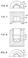
- the lead shielding sleeve shown in Figures 6-9 comprises a lower retaining portion 22 and an upper retaining portion 23, the upright edge 24 of the lower retaining portion fitting within the circumferential edge 25 of the upper retaining portion.
- a circumferential recess 26 in the lower retaining portion may comprise a rubber ring which can hold the reservoir in a resilient clamping within said retaining portion.
- the lower retaining portion furthermore has a bottom portion 27 having a hexagonal inner cross-section in which the cam-shaped projections 18a of the reservoir shown in Figures 1-3 fit exactly. As a result of this the reservoir is locked against rotation inside the said lower retaining portion.
- the upper retaining portion 23 also has a hexagonal inner cross-section 28 which corresponds to the circumferential shape of the screw cap shown in Figures 4-5.
- Velcro may be used as a holding means for the screw cap within the said upper retaining portion and is connected to the screw cap and to the inner wall of the said retaining portion.
Landscapes
- Health & Medical Sciences (AREA)
- Pharmacology & Pharmacy (AREA)
- Life Sciences & Earth Sciences (AREA)
- Animal Behavior & Ethology (AREA)
- General Health & Medical Sciences (AREA)
- Public Health (AREA)
- Veterinary Medicine (AREA)
- Medical Preparation Storing Or Oral Administration Devices (AREA)
- Infusion, Injection, And Reservoir Apparatuses (AREA)
- Medicinal Preparation (AREA)
Abstract
Description
- The invention relates to a shielded holder for at least one capsule for oral administration, which capsule contains a substance which is dangerous for the environment, in particular a radioactive composition, said holder comprising an internal reservoir in which the capsule is contained and a shielding sleeve surrounding the reservoir, which shielding sleeve is preferably manufactured from lead. The reservoir is proportioned so that it fits within said shielding sleeve.
- Such a shielded holder is described in US-A-2915640, including a bottle for containing the orally administrable material, said bottle having a body and a cap closure.
- Reservoirs for holding at least one capsule for oral administration, which reservoirs comprise a body and a cap, of which the body is shaped substantially in the form of a cylinder, having a closed lower end and an open upper end that can be closed by said cap, are well known.
- From NL-A-7404778 and 7507574 devices are known that can dispense pills one by one. These devices are equipped with a mechanism to conduct each time one single pill from a quantity contained in the holder to a dispenser opening in the holder and to eject such a pill from the holder.
- In US-A-2551710 a faceted tubing is described which can be used for a container; as an example, the tubing carries internally longitudinal serrations or ribs which serve as faceting means.
- In US-A-4171753 a holder for capsules, pills and similar objects is described which is intended to operate simply and which can be used for or adapted to pills and similar objects having various shapes and sizes. For this purpose this known holder comprises a hollow outer tube closed at one end and open at the other, and a dispensing mechanism. A hollow inner tube, insertable into the outer tube, has means for conforming the inner diameter thereof to the shape of the objects. Further the inner tube is slotted at diametrically opposite sides for allowing entry of a pusher and allowing exit of the objects.
- As mentioned above, the present invention relates to a shielded holder for at least one capsule for oral administration which capsule comprises a substance which is dangerous for the environment, in particular a radioactive composition. It is often desirable to administer a substance which is dangerous for the environment orally to a patient. Such a substance is usually dissolved and given the patient to drink. It will be obvious that such an administration is not very comfortable for the patient and moreover is not safe for him/herself and for his/her environment. In fact, the risk of spilling the solution given to drink is great. It is therefore common practice to administer such dangerous substances in the form of capsules, in which the capsule wall, which is preferably manufactured from gelatin, dissolves in the stomach and releases the substance. A well-known example of such a dangerous substance for oral administration, namely a radioactive substance, is radioactive iodine, in particular iodine-131. This radioactive iodine is administered, for example, as sodium iodide, in a suitable capsule, e.g. a gelatin capsule, to a patient, either as a diagnostic, namely to provide information on the functioning of the thyroid gland, or as a therapeutic, namely to control thyroid gland tumors. Such a reservoir should allow enclosure within an at least substantially cylindrical shielding sleeve, should have a closed bottom and should be closable at its open upper end by means of a cap, for example, a screw cap, or a cap having a bayonet catch or the like. Such a reservoir having a capsule comprises a I-131-containing composition is placed available while enclosed in a lead shielding sleeve. The idea of this is that the patient opens the shielding sleeve, unscrews the cap from the reservoir, lets the capsule from the reservoir slide into his mouth and finally swallows the capsule with some water. In practice a cylindrical glass vial is used as a reservoir.
- It has been found, however, that the capsule, although dry and accomodated in the reservoir with some sufficient amount of "play", often "sticks" in the vial when the opened vial is turned upside down to let the capsule slide into the mouth. This problem presents itself for capsules which comprise radioactive compositions, for example, iodine-131 compositions. The patient then has to try to get the capsule out of the reservoir yet by shaking the inverted reservoir or by using an instrument, for example, tweezers. A particurlarly inconvenient situation and moreover unsafe, especially due to to the extra long time in which the environment of the patient is exposed to the dangerous substance, in particular the radioactive radiation which is released from the capsule. It has further been found that the problem is not solved by using a synthetic material instead of a glass reservoir.
- The inventor has now found that this problem can be solved by including a plurality of longitudinal ribs on the interior surface of the reservoir cylinder. The " sticking" of the capsule or capsules in the reservoir proves to be obviated substantially when such a reservoir is used, so that easy dispense of said capsule is ensured.
- The first-mentioned US patent (US-A-2915640) does not suggest in any way a solution to the above problem. The other known capsule reservoirs were not developed or intended for containing capsules with radioactive materials.
- A further improvement of the reservoir can be achieved by giving the bottom of the reservoir a convex construction internally. The so-called "sticking", in which the capsule or capsules do not leave the reservoir when same is opened and inverted has been found to occur not at all any longer when a reservoir is used which internally has a number of longitudinal ribs and a convex bottom.
- It is furthermore of the utmost importance that capsules comprising substances which are dangerous for the environment, in particular radioactive radiation-emitting compositions, remain inside the shielding sleeve as long as possible. It has so far been common practice, after opening the shielding sleeve, to take the reservoir out of the shielding sleeve and then to open it by unscrewing the cap. It will be obvious that the patient's environment is exposed to the unprotected dangerous substance, in particular the radiation of a radioactive composition for a comparatively long period of time.
- As another aspect of the present invention it was found that the said exposure time can be considerably reduced by ensuring that the bottom portion of the reservoir is externally non-rotationally symmetrical and is proportioned so that it fits within the shielding sleeve which has a bottom portion with a likewise non-rotationally symmetrical inner wall, preferably with an internal cross-section which is a triangular to dodecagonal or forms a segment of a circle, so that the reservoir is locked against rotation within the sleeve. As a result of this it has become possible, during the action of opening the reservoir, to leave the reservoir inside the shielding sleeve - which, of course, is open at the top - and during unscrewing take hold the cap of the reservoir with one hand and to hold the outside of the shielding sleeve with the other hand. In this manner, the patient's environment is exposed to the dangerous substance for an shorter period of time.
- In a suitable embodiment, the externally non-rotationally symmetrical bottom portion of the reservoir is constructed so as to have a circumferential shape which is triangular to dodecagonal or corresponds to the segment of a circle. The circumferential shape may correspond to the internal cross-section of the bottom portion of the shielding sleeve, but this is not necessary. It is only of importance that the reservoir is locked against rotation inside the shielding sleeve during unscrewing the cap.
- In another likewise particularly favourable embodiment the reservoir is manufactured from a suitable, non-deformable synthetic material. Synthetic materials, provided they are compatible with the dangerous substance to be swallowed and provided they are inert with respect to the capsule with the composition present therein, are to be preferred to glass, because the reservoirs manufactured from said synthetic materials cannot easily break. It frequently occurs, that the glass reservoir during transport or during the actions preceding the administration of the capsule or capsules breaks, as a result of which the capsule or capsules can no longer be swallowed or can be swallowed with great difficulty only. This disadvantage can be avoided by manufacturing the reservoir from a suitable synthetic material. Moreover, the radioactivity of a composition must always be measured before it is administered to a patient. This measurement can more safely be carried out when the composition is accommodated in a synthetic material reservoir, so without the danger of fracture. Synthetic material articles can easily be manufactured in the desired shape by injection-moulding. In the above preferred embodiment the bottom of the reservoir, which thus is manufactured from a suitable synthetic material, externally comprises a plurality of rib-like elements which fit within the bottom portion of the shielding sleeve and which extend perpendicularly to the bottom of the reservoir. It has been found that polyethylene terephthalate is an excellently suitable synthetic material for the reservoir when the reservoir serves for accommodating one or more capsules comprising radioactive composition, in particular a iodine-131-containing composition. This synthetic material unites in itself a number of favourable properties, for example, suitability to manufacture a reservoir from it, resistance to radioactive radiation and, when used for capsules comprising iodine-131-containing compositions, impermeability to iodine vapour.
- It is advantageous to provide the above-mentioned synthetic material reservoir externally with a plurality of longitudinal ribs so that it can better withstand bending forces. In fact, when the reservoir is taken out of the shielding sleeve, lateral forces may be exerted on the said reservoir. In an embodiment which is favourable for production, the said longitudinal ribs provided on the outside of the reservoir are constructed so that at least a part there of continues as the rib-like elements provided on the bottom.
- In a further preferred embodiment the rib-like elements are provided on the bottom of the reservoir in such manner that the collective rib-like elements on the bottom of the reservoir show a cross-like or star-like cross-section and may be provided at the ends remote from the common axis with a plurality of breakable or bendable cam-like projections extending in the longitudinal direction of the reservoir. It can easily occur when the cap is screwed on the reservoir that too large a force is exerted on the cap. The same thing occures when it is tried to rotate the cap in the reverse direction although the intention was to unscrew it. Because the reservoir with its bottom is preferably locked against rotation inside the shielding sleeve, the result may be a torsional force on the reservoir which may cause fracture of the reservoir; fracture frequently occurs in particular with glass reservoirs. The above-mentioned breakable or bendable cam-like projections present an excellent safety in such cases, because when too large torsional forces are exerted on the reservoir, said projections can break off or bend over, as a result of which the reservoir further remains intact.
- In a preferred embodiment the preferably lead shielding sleeve of the above-mentioned holder according to the invention comprises two detachable portions within which the reservoir is enclosed, namely a lower retaining portion and an upper retaining portion, the lower retaining portion of the shielding sleeve internally comprising holding means for the reservoir so that after detaching the upper retaining portion the reservoir does not by itself drop out of the lower retaining portion when the said latter portion with the reservoir inside is held in the upside-down position. Various means are suitable to hold the reservoir inside the shielding sleeve, for example, a rubber ring which is connected in a circumferential groove in the inner wall of the lower retaining portion of the sleeve and which clamps the reservoir resiliently. The patient, after having removed the cap from the reservoir, can move the lower retaining portion with the reservoir inside in the upside down position to his mouth and swallow the capsule without the reservoir dropping out of the said retaining portion. In this manner the patient needs to perform fewer actions as a result of which the environment hence is exposed for a shorter period of time to the dangerous substance, while moreover he/she is better protected from the dangerous substance during swallowing the capsule, in particular from radioactive radiation thereof.
- In a further preferred embodiment the upper retaining portion of the shielding sleeve of the holder according to the invention has a square to dodecagonal cross-section over at least a part of its internal length in which the cap likewise having a square to dodecagonal circumferential shape fits. Now it is not necessary for the patient to first remove the upper retaining portion of the shielding sleeve before the cap can be unscrewed from the reservoir, but the cap can simply be unscrewed by rotating the upper and lower retaining portions of the shielding sleeve with respect to each other. As a result of this the patient's environment is exposed to the dangerous substance for even a shorter period of time. The cap and/or the upper retaining portion are/is provided with holding means for the cap within the said retaining portion so that the cap after unscrewing can be taken off simultaneously with the upper retaining portion. Velcro connected on the outside of the cap and on the inner wall of the said retaining portion constitutes an excellent means to hold the cap in the upper retaining portion.
- The invention will now be described in greater detail with reference to the accompanying drawings, in which
- Figure 1 is partly a longitudinal sectional view and partly a side elevation of a reservoir of a shielded holder according to the invention;
- Figures 2 and 3 are a plan view and a underneath view, respectively, of the same reservoir;
- Figures 4 and 5 are a plan view and a side elevation, respectively, of a screw cap for the reservoir shown in Figures 1-3; and
- Figures 6-9 show a lead shielding sleeve for the reservoir, of which Figures 6 and 7 show the upper retaining portion, Figure 7 as a cross-sectional view and Figure 6 as a (partly) underneath view, and Figures 8 and 9 show the lower retaining portion, Figure 8 as a cross-sectional view and Figure 9 as a (partly) plan view.
- The reservoir 11 shown in Figures 1-3 comprises an internally convex bottom 12, a
sidewall 14 reinforced externally withlongitudinal ribs 13, and an open upperend having screwthread 15 on which a screw cap as shown in Figures 4 and 5 can be screwed. The longitudinal inner ribs are referenced 16. As is shown clearest in Figure 3, four of the eight external reinforcing ribs are elongated downwards and constitute there two cross-wise placed rib-shapedelements 17 which extent perpendicularly to the bottom of the reservoir. Four cam-shapedprojections projections 18a can be bent and fit exactly within the hexagonal bottom portion (27 in Figures 8 and 9) of the shielding sleeve. In this manner they lock the reservoir in the shielding sleeve against rotation and also serve as a safety when too large torsional forces are exerted on the reservoir. The reservoir is manufactured from polyethylene terephthalate. - The
scew cap 19 shown in Figures 4 and 5 and manufactured from a suitable synthetic material e.g. polypropene, has an outer hexegonal shape and fits within the upper retaining portion of the lead shielding sleeve shown in Figures 6-9. For sealing purposes, the screw cap internally comprises anactive carbon filter 21 andmillipore paper filter 20 which are shown separately in Figure 5. - The lead shielding sleeve shown in Figures 6-9 comprises a
lower retaining portion 22 and anupper retaining portion 23, theupright edge 24 of the lower retaining portion fitting within thecircumferential edge 25 of the upper retaining portion. Acircumferential recess 26 in the lower retaining portion may comprise a rubber ring which can hold the reservoir in a resilient clamping within said retaining portion. The lower retaining portion furthermore has abottom portion 27 having a hexagonal inner cross-section in which the cam-shapedprojections 18a of the reservoir shown in Figures 1-3 fit exactly. As a result of this the reservoir is locked against rotation inside the said lower retaining portion. Theupper retaining portion 23 also has a hexagonalinner cross-section 28 which corresponds to the circumferential shape of the screw cap shown in Figures 4-5. Velcro may be used as a holding means for the screw cap within the said upper retaining portion and is connected to the screw cap and to the inner wall of the said retaining portion.
Claims (10)
- A shielded holder for holding at least one capsule for oral administration, which capsule contains a radioactive composition, in particular an iodine-131 containing compostion; said holder comprising an internal reservoir, in which the capsule is contained, and a shielding sleeve surrounding the reservoir; which shielding sleeve in preferably manufactured from lead, and which reservoir is proportioned so that it fits within said shielding sleeve and comprises a body (11) and a cap (19), which reservoir body is shaped substantially in the form of a cylinder, having a closed lower end (12) and an open upper end that can be closed by said cap; said reservoir body being characterized in that it includes a plurality of longitudinal ribs (16) on the interior surface of the cylinder.
- A shielded holder according to claim 1, wherein the closed lower end of the reservoir is internally convex.
- A shielded holder according to claim 1 or 2, wherein the reservoir is manufactured from a non-deformable synthetic material, preferably from polyethylene terephthalate.
- A shielded holder according to any of claims 1-3, wherein a bottom portion of the reservoir has an external non-rotational symmetry proportioned to fit within a bottom portion of the shielding sleeve which has an internal non-rotational symmetry corresponding to the external non-rotational symmetry of the reservoir; thereby enabling the reservoir to be locked against rotation within the shielding sleeve.
- A shielded holder according to claim 4, wherein the external non-rotational symmetry of the reservoir and the internal non-rotational symmetry of the shielding sleeve are triangular to dodecagonal or corresponds to a segment of a circle.
- A shielded holder according to any of claims 1-5, wherein the reservoir further includes a plurality of external reinforcing longitudinal ribs, a portion of which continue as rib-shaped elements along the bottom of the reservoir and extend perpendicularly to the bottom of the reservoir.
- A shielded holder according to claim 6, wherein the rib-shaped elements along the bottom of the reservoir fit within a bottom portion of the shielding sleeve and thereby enable the reservoir to be locked against rotation within the shielding sleeve.
- A shielded holder according to claim 6 or 7, wherein the collective rib-shaped elements along the bottom of the reservoir show a cross-like or star-like cross-section and are provided with ends remote from a common axis with breakable or bendable cam-shaped projections extending in a longitudinal direction.
- A shielded holder according to any of claims 1-8, wherein the shielding sleeve consists of two detachable portions; a lower detachable portion for retaining the reservoir and including holding means for the reservoir which prevents the reservoir from dropping out of the lower detachable portion when the lower detachable portion is held in an upside-down position; and an upper detachable portion for retaining the cap for the reservoir and having a square to dodecagonal internal cross-action which corresponds to the shape of the cap.
- A shielded holder according to claim 9, wherein the holding means comprises a rubber ring, and/or wherein the upper detachable portion includes retaining means for retaining the cap within the upper detachable portion.
Applications Claiming Priority (3)
| Application Number | Priority Date | Filing Date | Title |
|---|---|---|---|
| NL8801947 | 1988-08-04 | ||
| NL8801947 | 1988-08-04 | ||
| PCT/US1989/003272 WO1990001279A1 (en) | 1988-08-04 | 1989-07-28 | Reservoir for capsule for oral administration |
Publications (3)
| Publication Number | Publication Date |
|---|---|
| EP0427786A1 EP0427786A1 (en) | 1991-05-22 |
| EP0427786A4 EP0427786A4 (en) | 1991-12-18 |
| EP0427786B1 true EP0427786B1 (en) | 1995-04-05 |
Family
ID=19852711
Family Applications (1)
| Application Number | Title | Priority Date | Filing Date |
|---|---|---|---|
| EP89909495A Expired - Lifetime EP0427786B1 (en) | 1988-08-04 | 1989-07-28 | Reservoir for capsule for oral administration |
Country Status (8)
| Country | Link |
|---|---|
| US (2) | US5253761A (en) |
| EP (1) | EP0427786B1 (en) |
| JP (1) | JP2927851B2 (en) |
| AT (1) | ATE120620T1 (en) |
| AU (1) | AU642129B2 (en) |
| CA (1) | CA1314635C (en) |
| DE (1) | DE68922105T2 (en) |
| WO (1) | WO1990001279A1 (en) |
Families Citing this family (8)
| Publication number | Priority date | Publication date | Assignee | Title |
|---|---|---|---|---|
| US4891165A (en) * | 1988-07-28 | 1990-01-02 | Best Industries, Inc. | Device and method for encapsulating radioactive materials |
| ATE120620T1 (en) * | 1988-08-04 | 1995-04-15 | Mallinckrodt Inc | CONTAINER FOR ORAL CAPSULES. |
| WO1994007764A1 (en) * | 1992-09-29 | 1994-04-14 | Hazpak Pty. Ltd. | Containers for potentially hazardous substances |
| EP0856303A1 (en) | 1997-02-03 | 1998-08-05 | Mallinckrodt Medical B.V. | Handling tool for the oral self-administration of a radioactive capsule |
| EP1632268A1 (en) * | 2004-09-03 | 2006-03-08 | Mallinckrodt Inc. | Container for radioactive material |
| US7199375B2 (en) * | 2004-10-12 | 2007-04-03 | Bard Brachytherapy, Inc. | Radiation shielding container that encloses a vial of one or more radioactive seeds |
| US7451870B2 (en) | 2006-02-06 | 2008-11-18 | Zimmer Dental, Inc. | Medical implant package with a cap having a cavity |
| CA2653943C (en) * | 2006-08-24 | 2013-02-19 | Areva Federal Services Llc | Transportation container and assembly |
Family Cites Families (20)
| Publication number | Priority date | Publication date | Assignee | Title |
|---|---|---|---|---|
| US2551710A (en) * | 1945-05-04 | 1951-05-08 | Extruded Plastics Inc | Light diffusing thermoplastic tube to encircle an elongated lighting element |
| US2812874A (en) * | 1955-08-17 | 1957-11-12 | Plastic Molded Arts Corp | Reinforced double wall container |
| US2868411A (en) * | 1957-03-05 | 1959-01-13 | Kesselman Jacob | Holder for milk cartons or the like |
| US2915640A (en) * | 1957-04-29 | 1959-12-01 | Olin Mathieson | Container |
| BE618091A (en) * | 1961-05-26 | |||
| US3256441A (en) * | 1962-11-26 | 1966-06-14 | Abbott Lab | Container system for radioactive material |
| FR1501968A (en) * | 1966-09-30 | 1967-11-18 | Parisienne D Expansion Chimiqu | Packaging article for object of revolution |
| ES166618Y (en) * | 1971-03-03 | 1971-11-16 | Fernandez Robles | A PERFECT PACKAGING. |
| US3860111A (en) * | 1973-06-11 | 1975-01-14 | Larry G Thompson | Pill container and dispenser |
| US3941237A (en) * | 1973-12-28 | 1976-03-02 | Carter-Wallace, Inc. | Puck for and method of magnetic conveying |
| US4040536A (en) * | 1975-05-05 | 1977-08-09 | R. P. Scherer Corporation | Locking hard gelatin capsule |
| US4054208A (en) * | 1975-10-16 | 1977-10-18 | Lowe Fred H | Double walled insulated medicinal tablet container |
| US4011962A (en) * | 1976-06-01 | 1977-03-15 | Vca Corporation | Two piece closure for containers |
| US4171753A (en) * | 1976-12-10 | 1979-10-23 | Bastiaan Vreede | Holder for capsules, pills and similar objects |
| GB2034663B (en) * | 1978-11-07 | 1983-09-01 | Yoshino Kogyosho Co Ltd | Synthetic resin thin-walled bottle |
| US4613042A (en) * | 1985-04-25 | 1986-09-23 | Kar-Glo Industries, Inc. | Lamp holder |
| US5014868A (en) * | 1986-04-08 | 1991-05-14 | Ccl Custom Manufacturing, Inc. | Holding device for containers |
| US4756407A (en) * | 1987-12-14 | 1988-07-12 | Larsen Ernest F | Container apparatus for medicinal tablets |
| ATE120620T1 (en) * | 1988-08-04 | 1995-04-15 | Mallinckrodt Inc | CONTAINER FOR ORAL CAPSULES. |
| US5082135A (en) * | 1990-05-08 | 1992-01-21 | Dart Industries Inc. | Container for storing and dispensing goods |
-
1989
- 1989-07-28 AT AT89909495T patent/ATE120620T1/en not_active IP Right Cessation
- 1989-07-28 EP EP89909495A patent/EP0427786B1/en not_active Expired - Lifetime
- 1989-07-28 AU AU40699/89A patent/AU642129B2/en not_active Ceased
- 1989-07-28 US US07/646,627 patent/US5253761A/en not_active Expired - Lifetime
- 1989-07-28 DE DE68922105T patent/DE68922105T2/en not_active Expired - Fee Related
- 1989-07-28 WO PCT/US1989/003272 patent/WO1990001279A1/en not_active Ceased
- 1989-07-28 JP JP1508904A patent/JP2927851B2/en not_active Expired - Fee Related
- 1989-08-01 CA CA000607192A patent/CA1314635C/en not_active Expired - Fee Related
-
1996
- 1996-11-22 US US08/754,335 patent/US5752603A/en not_active Expired - Fee Related
Also Published As
| Publication number | Publication date |
|---|---|
| DE68922105D1 (en) | 1995-05-11 |
| EP0427786A1 (en) | 1991-05-22 |
| WO1990001279A1 (en) | 1990-02-22 |
| JP2927851B2 (en) | 1999-07-28 |
| DE68922105T2 (en) | 1995-08-10 |
| JPH04500021A (en) | 1992-01-09 |
| AU642129B2 (en) | 1993-10-14 |
| EP0427786A4 (en) | 1991-12-18 |
| US5752603A (en) | 1998-05-19 |
| CA1314635C (en) | 1993-03-16 |
| US5253761A (en) | 1993-10-19 |
| AU4069989A (en) | 1990-03-05 |
| ATE120620T1 (en) | 1995-04-15 |
Similar Documents
| Publication | Publication Date | Title |
|---|---|---|
| ES2338254T3 (en) | PACKAGING FOR EXTEMPORARY PRODUCTS, IN PARTICULAR MEDICINAL, PHARMACEUTICAL, COSMETIC OR SIMILAR PRODUCTS. | |
| RU2471474C2 (en) | Agent dispenser and sublingual device | |
| US2915640A (en) | Container | |
| JP5049785B2 (en) | Radioactive material container | |
| ES2577383T3 (en) | Dispensing device | |
| ES2649142T3 (en) | Container for containing and dispensing solid medicinal pills | |
| US9815611B2 (en) | Device and method for singularized dispensing of solid portions | |
| US6478155B2 (en) | Cap-mounted pill container | |
| US11266573B2 (en) | System for dosing and dispensing medication | |
| JP6921806B2 (en) | Adapter for connecting the dispenser to the container | |
| KR20200068550A (en) | Pill bottle with removable pill container cap | |
| US5253761A (en) | Reservoir for capsule for oral administration | |
| AU2020239363A1 (en) | Applicator for oral administration of a swallowable object to a patient | |
| US5478311A (en) | Hand held combination pill crushing and dispensing device | |
| ES2394408T3 (en) | Device for the conditioning of two products to be mixed, and for the distribution of the mixture of these two products | |
| US4185740A (en) | Disposable capsules | |
| US11469007B2 (en) | Compression member for biohazardous material transporting pig | |
| KR920003127B1 (en) | Dosage device | |
| US3357545A (en) | Dental materials and apparatus for preparing the same | |
| ES2741900T3 (en) | Packaging device for solid medicine (s), storage and distribution devices and distribution procedure for such medicine (s) | |
| KR950000685Y1 (en) | Potion bottle with medicine cup | |
| EP0856303A1 (en) | Handling tool for the oral self-administration of a radioactive capsule | |
| IT9021929A1 (en) | DEVICE FOR ESTEMPORANEA PREPARATION AND DELIVERY OF SOLUTIONS |
Legal Events
| Date | Code | Title | Description |
|---|---|---|---|
| PUAI | Public reference made under article 153(3) epc to a published international application that has entered the european phase |
Free format text: ORIGINAL CODE: 0009012 |
|
| 17P | Request for examination filed |
Effective date: 19910202 |
|
| AK | Designated contracting states |
Kind code of ref document: A1 Designated state(s): AT BE CH DE FR GB IT LI LU NL SE |
|
| A4 | Supplementary search report drawn up and despatched |
Effective date: 19911031 |
|
| AK | Designated contracting states |
Kind code of ref document: A4 Designated state(s): AT BE CH DE FR GB IT LI LU NL SE |
|
| RAP1 | Party data changed (applicant data changed or rights of an application transferred) |
Owner name: MALLINCKRODT, INC. |
|
| 17Q | First examination report despatched |
Effective date: 19930429 |
|
| GRAA | (expected) grant |
Free format text: ORIGINAL CODE: 0009210 |
|
| AK | Designated contracting states |
Kind code of ref document: B1 Designated state(s): AT BE CH DE FR GB IT LI LU NL SE |
|
| PG25 | Lapsed in a contracting state [announced via postgrant information from national office to epo] |
Ref country code: LI Effective date: 19950405 Ref country code: CH Effective date: 19950405 Ref country code: AT Effective date: 19950405 |
|
| REF | Corresponds to: |
Ref document number: 120620 Country of ref document: AT Date of ref document: 19950415 Kind code of ref document: T |
|
| REF | Corresponds to: |
Ref document number: 68922105 Country of ref document: DE Date of ref document: 19950511 |
|
| ET | Fr: translation filed | ||
| ITF | It: translation for a ep patent filed | ||
| REG | Reference to a national code |
Ref country code: CH Ref legal event code: PL |
|
| PLBE | No opposition filed within time limit |
Free format text: ORIGINAL CODE: 0009261 |
|
| STAA | Information on the status of an ep patent application or granted ep patent |
Free format text: STATUS: NO OPPOSITION FILED WITHIN TIME LIMIT |
|
| 26N | No opposition filed | ||
| PGFP | Annual fee paid to national office [announced via postgrant information from national office to epo] |
Ref country code: LU Payment date: 19960601 Year of fee payment: 8 |
|
| PGFP | Annual fee paid to national office [announced via postgrant information from national office to epo] |
Ref country code: SE Payment date: 19960618 Year of fee payment: 8 |
|
| PGFP | Annual fee paid to national office [announced via postgrant information from national office to epo] |
Ref country code: NL Payment date: 19960624 Year of fee payment: 8 |
|
| PGFP | Annual fee paid to national office [announced via postgrant information from national office to epo] |
Ref country code: BE Payment date: 19960625 Year of fee payment: 8 |
|
| PG25 | Lapsed in a contracting state [announced via postgrant information from national office to epo] |
Ref country code: LU Free format text: LAPSE BECAUSE OF NON-PAYMENT OF DUE FEES Effective date: 19970728 |
|
| PG25 | Lapsed in a contracting state [announced via postgrant information from national office to epo] |
Ref country code: SE Effective date: 19970729 |
|
| PG25 | Lapsed in a contracting state [announced via postgrant information from national office to epo] |
Ref country code: BE Free format text: LAPSE BECAUSE OF NON-PAYMENT OF DUE FEES Effective date: 19970731 |
|
| BERE | Be: lapsed |
Owner name: MALLINCKRODT INC. Effective date: 19970731 |
|
| PG25 | Lapsed in a contracting state [announced via postgrant information from national office to epo] |
Ref country code: NL Free format text: LAPSE BECAUSE OF NON-PAYMENT OF DUE FEES Effective date: 19980201 |
|
| NLV4 | Nl: lapsed or anulled due to non-payment of the annual fee |
Effective date: 19980201 |
|
| EUG | Se: european patent has lapsed |
Ref document number: 89909495.7 |
|
| PGFP | Annual fee paid to national office [announced via postgrant information from national office to epo] |
Ref country code: FR Payment date: 19990630 Year of fee payment: 11 |
|
| PGFP | Annual fee paid to national office [announced via postgrant information from national office to epo] |
Ref country code: GB Payment date: 19990702 Year of fee payment: 11 Ref country code: DE Payment date: 19990702 Year of fee payment: 11 |
|
| PG25 | Lapsed in a contracting state [announced via postgrant information from national office to epo] |
Ref country code: GB Free format text: LAPSE BECAUSE OF NON-PAYMENT OF DUE FEES Effective date: 20000728 |
|
| GBPC | Gb: european patent ceased through non-payment of renewal fee |
Effective date: 20000728 |
|
| PG25 | Lapsed in a contracting state [announced via postgrant information from national office to epo] |
Ref country code: FR Free format text: LAPSE BECAUSE OF NON-PAYMENT OF DUE FEES Effective date: 20010330 |
|
| REG | Reference to a national code |
Ref country code: FR Ref legal event code: ST |
|
| PG25 | Lapsed in a contracting state [announced via postgrant information from national office to epo] |
Ref country code: DE Free format text: LAPSE BECAUSE OF NON-PAYMENT OF DUE FEES Effective date: 20010501 |
|
| PG25 | Lapsed in a contracting state [announced via postgrant information from national office to epo] |
Ref country code: IT Free format text: LAPSE BECAUSE OF NON-PAYMENT OF DUE FEES;WARNING: LAPSES OF ITALIAN PATENTS WITH EFFECTIVE DATE BEFORE 2007 MAY HAVE OCCURRED AT ANY TIME BEFORE 2007. THE CORRECT EFFECTIVE DATE MAY BE DIFFERENT FROM THE ONE RECORDED. Effective date: 20050728 |