EP0427716B1 - A method of measuring radiation for a radiation measuring device - Google Patents
A method of measuring radiation for a radiation measuring device Download PDFInfo
- Publication number
- EP0427716B1 EP0427716B1 EP88907288A EP88907288A EP0427716B1 EP 0427716 B1 EP0427716 B1 EP 0427716B1 EP 88907288 A EP88907288 A EP 88907288A EP 88907288 A EP88907288 A EP 88907288A EP 0427716 B1 EP0427716 B1 EP 0427716B1
- Authority
- EP
- European Patent Office
- Prior art keywords
- integration interval
- actual integration
- interval
- geiger
- radiation
- Prior art date
- Legal status (The legal status is an assumption and is not a legal conclusion. Google has not performed a legal analysis and makes no representation as to the accuracy of the status listed.)
- Expired
Links
- 230000005855 radiation Effects 0.000 title claims abstract description 44
- 238000000034 method Methods 0.000 title claims description 9
- 238000005259 measurement Methods 0.000 claims abstract description 33
- 230000035945 sensitivity Effects 0.000 claims abstract description 4
- 230000010354 integration Effects 0.000 claims description 76
- 230000003247 decreasing effect Effects 0.000 claims description 7
- 238000004364 calculation method Methods 0.000 claims description 6
- 238000004904 shortening Methods 0.000 claims description 2
- 238000007493 shaping process Methods 0.000 abstract description 4
- 239000000523 sample Substances 0.000 description 19
- 238000012545 processing Methods 0.000 description 10
- 238000011156 evaluation Methods 0.000 description 4
- 239000004973 liquid crystal related substance Substances 0.000 description 3
- 238000010586 diagram Methods 0.000 description 2
- 238000005286 illumination Methods 0.000 description 2
- 230000011664 signaling Effects 0.000 description 2
- 230000003213 activating effect Effects 0.000 description 1
- 230000003044 adaptive effect Effects 0.000 description 1
- 230000002730 additional effect Effects 0.000 description 1
- 238000006243 chemical reaction Methods 0.000 description 1
- 238000011109 contamination Methods 0.000 description 1
- 230000001419 dependent effect Effects 0.000 description 1
- 238000001514 detection method Methods 0.000 description 1
- 238000003745 diagnosis Methods 0.000 description 1
- 230000000694 effects Effects 0.000 description 1
- 230000007613 environmental effect Effects 0.000 description 1
- 239000000383 hazardous chemical Substances 0.000 description 1
- 239000007788 liquid Substances 0.000 description 1
- 230000007774 longterm Effects 0.000 description 1
- 230000007257 malfunction Effects 0.000 description 1
- 238000012544 monitoring process Methods 0.000 description 1
- 239000010453 quartz Substances 0.000 description 1
- 230000003252 repetitive effect Effects 0.000 description 1
- 238000005070 sampling Methods 0.000 description 1
- VYPSYNLAJGMNEJ-UHFFFAOYSA-N silicon dioxide Inorganic materials O=[Si]=O VYPSYNLAJGMNEJ-UHFFFAOYSA-N 0.000 description 1
- 238000012360 testing method Methods 0.000 description 1
- 230000000007 visual effect Effects 0.000 description 1
Images

Classifications
-
- G—PHYSICS
- G01—MEASURING; TESTING
- G01T—MEASUREMENT OF NUCLEAR OR X-RADIATION
- G01T1/00—Measuring X-radiation, gamma radiation, corpuscular radiation, or cosmic radiation
- G01T1/16—Measuring radiation intensity
- G01T1/18—Measuring radiation intensity with counting-tube arrangements, e.g. with Geiger counters
Definitions
- the present invention relates to a method of measuring radiation for a radiation measurement device with at least two Geiger-Müller counter tubes of different sensitivity, high voltage supply means in connection with each of said Geiger-Müller counter tubes and microprocessor means including program storage means and random access memory means capable of switching between said Geiger-Müller tubes based on said radiation intensity whereby at least one Geiger-Müller counter tube generates pulses wherein an actual integration interval is determined by a measurement algorithm.
- Geiger-Müller counters a gas filled chamber is employed in which is incorporated two electrodes. The ionization produced by radiation dissipates part or all of its energy by generating electron - ion pairs. A count is registered each time a pulse of voltage exceeds a minimum value established.
- EP-A 0 151 880 refers to a particular radiation detector using Geiger-Müller counter tubes, in which instead of counting radiation pulses the elapsed time interval to the incident of the first strike is determined. This is done to avoid negative influences of dead time and thus to provide a linear read-out.
- the method initially mentioned is characterized by setting the actual integration interval to the value of the previous integration interval or to a fixed value at start up; retrieving a check interval from the actual integration interval, by taking the square root of the actual integration interval and adding a constant; calculating the average of the Geiger-Müller counter pulses for the check interval of time; selecting a specific measuring range and specific values for parameters of the algorithm according to the average, said values being the upper and the lower limit for the actual integration interval and the upper and lower limit for the allowed statistical fluctuation of the radiation intensity in said measuring range; comparing the actual integration interval to the upper limit; determining whether the actual integration interval falls below or above the upper limit for the actual integration interval; setting the integration interval to the upper limit if it was above the limit and letting the integration interval unchanged if it was less or equal this limit; calculating the average value of the counted Geiger-Müller pulses during the actual integration interval; determining a tolerance band by weighting said average value with the given values of the upper and lower limit of the statistical fluctuation; using the
- a preferred method is characterized in that the internal tables for minimum and maximum integration time, threshold setting and short check interval are continuously updated every second. Further it is preferred that specific values are assigned to the paramters, the upper and lower limit of the actual integration interval, as well as to f+ and f-, the limits of statistical fluctuation for steady state operation in the particular dose rate range, wherein parameters are selected from tables which are programmed in unchanging storage means.
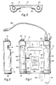
- Figure 1 shows a front view of a portable radiation measurement device 10 constructed in accordance with the present invention.
- the device 10 is housed in a rugged case 12 protecting it against environmental hazards.
- the device may be used as a portable or stationary system.
- All of the controls are located on the front side of the case 12 including a digital and analog visual liquid crystal display 14.
- An on-off switch 16 controls power to the device.
- a push button switch 18 controls an acoustic pulse signaling and acoustic alarm threshold feature to be described in detail.
- a push button switch 20 is provided to activate the display illumination. The on-off switch 16 and push button switches 18 and 20 are easily operated while the user (not shown) is wearing gloves.
- a series of hooks 22 will accommodate a carrier belt (not shown) to be worn by the operator, allowing freedom of the operator's hands while insuring optimum visibility of the display 14 and controls.
- An abbreviated set of operator instructions 24 are affixed to the front of the case 12.
- the device 10 has internal water-tight cylindrical cavities or compartments 26 and 28. Each compartment is sealed with a water-tight lock, 30 and 32.
- the probe compartment 26 is capable of housing an optional external probe 34 (shown in outline form) which may be utilized as an alternative to the internal measurement counters to be described herein.
- the external probe contains an alpha-beta gamma measurement counter.
- other measurement probes such as telescopic probes, liquid monitoring probes, large-area contamination probes and scintillation probes, may be utilized with the device 10.
- a probe connector 36 extends outward from the case 12. The connector will receive a cable 38 which in turn may be connected to one of a variety of different probes for radiation measurement.
- the other compartment 28 houses batteries 40 to provide a power supply for the device.
- the batteries are shown in outline form in Figure 1.
- Figure 2 shows a side view and Figure 3 shows a top view of the device 10.
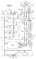
- FIG. 4 shows a block diagram of the device 10.
- Two Geiger-Muller counters 42 and 44 of different sensitivity, provide high and low dosage response.
- a central processing unit microprocessor 46 selectively activates either of the Geiger-Muller counters, 42 or 44, by selectively activating a high voltage supply 48.
- the central processing unit 46 automatically switches between Geiger-Muller counters providing a wide range of measuring ranges.
- the measuring range is from .50 micro sieverts per hour (micro Sv/h) to 5 Sv/h.
- the high voltage supply 48 is powered in one of two ways. The power is supplied from either batteries 40 housed within internal compartment 28 or, alternatively, from an external power supply (not shown) through serial interface connector 50.
- the serial interface connector 50 and the probe connector 36 have caps 51 to protect the connectors when not in use.
- external probes such as the probe 52 may be connected via connector 36.
- the external probe 52 will provide identification of the type of probe connected by circuit 54.
- a pair of Geiger-Muller counters 42′ and 44′ are utilized, however, other types of measurement devices might be used.
- the internal Geiger-Muller counters 42 and 44 are bypassed.
- a quartz oscillator 56 is provided.
- a watch dog, self-checking circuit 58 provides continuous self-checking and guards against component malfunction.
- the signal voltage received from the operational Geiger-Muller counters, 42 or 44 is fed to pulse shaping devices 60 and 62, respectively.
- Each pulse shaping device is connected to a high speed counter 64 which is in turn connected to the central processing unit 46.
- the high speed counter keeps track of the pulses delivered by the Geiger-Muller counter tubes during fixed time sampling periods. Every second the number of accumulated pulses, the count rate per second, is read by the central processing unit microprocessor and then the counter is restarted.
- a measurement algorithm is programmed and stored in unchanging storage 66.
- the central processing unit 46 maintains and updates internal tables in a random access memory 68.
- a multifunction input-output chip 70 interfaces with the liquid crystal display 14 as well as the scale illumination switch 20 and the acoustic pulse signaling switch 18. Acoustic beeper 72 is also connected to the input-output chip 70. Control of the high voltage supply 48 is also accomplished by the input-output chip 70.
- the serial interface connector 50 extending from the case is provided in order to connect the device 10 to an external power supply or to an external computer (not shown).
- An additional circuit (not shown in the drawings) monitors the current through the Geiger-Muller counters 42 and 44 and activates an overflow warning signal if the current exceeds a certain threshold.
- a display value is generated derived from the counter value of the high speed counter 64 in conjunction with the appropriate state and calibration tables contained in the random access memory 68.
- the RAM tables contain information for each measurement range that controls the actual processing of the pulse generated from the Geiger-Muller counters.
- the RAM tables also contain calibration information to convert the averaged count value to technical radiation units in sieverts/h.
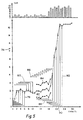
- a pair of graphs 76 illustrate the measurement algorithms and the operation of the device 10 for a hypothetical radiation reading.
- the measurement algorithm allows for the random or stochastic nature of radiation and adapts itself to the statistical requirements of the particular dose rate. Three distinct operational states are shown; start up, steady state and step response.
- the upper graph in Figure 5 gives the actual counter values in counts per second on the y ordinate versus the time on the x ordinate. Initially, the radiation averages about two counts per second stepping up to approximately 10 counts per second after 18 seconds.
- the lower graph of Figure 5 shows the averaged counts per second value after processing by the instrument logic.
- the resulting value is derived from converting the counts per second average to technical units based on conversion tables for Geiger-Muller tubes which are incorporated in the random access memory 68.
- the ordinate at the left hand margin indicates power up of the device 10,
- the start-up time is approximately 2 seconds.
- the measurement algorithm operates and expands the integration time up to a specific maximum dependent on the current mean value.
- the bars 78 below the curve of resultant counts per second average values show the increasing length of the integration interval.
- Each second a new mean value is calculated based on the current integration interval.
- This information is converted to sieverts/h (Sv/h) and then displayed on the liquid crystal display 14.
- the integration intervals in the steady state operation are of fixed length, continuously shifted to provide the most current values as indicated by bars 80 above the curve.
- An adaptive threshold setting allows for small, statistical fluctuations of the long term mean value and is illustrated by curves 82 and 84 below and above the curve of counts per second average values. Additionally, a comparatively short, internal check interval reflects short term variation and is illustrated by dashed lines 86. As long as the measurement value generated on the basis of the short check interval stays within the currently set threshold, as shown by curves 82 and 84, steady state operation is assumed. This guarantees long integration times even at highly fluctuating low dose rates.
- a sudden change in radiation shown after 18 seconds on the graphs 76, has a dramatic effect on the value derived from the check interval.
- the main integration time 88 shrinks back, thus assigning more weight to the most recently measured counter values.
- the degree of shrinking of the main integration interval and the short check interval is coupled to the dose rate evaluation.
- the upward change in radiation was rather small and steady state characteristics are quickly reestablished.
- a maximum integration time (up to 240 seconds) is selected for the current dose rate reading based on optimum statistic performance. Similar to startup conditions, the main integration interval is allowed to expand to this maximum value. Once the maximum integration time is established and steady-state conditions persist, this new fixed interval 92 is shifted to supply the average of the most recent values.
- the internal tables for minimum and maximum integration time, threshold setting and short check interval are continuously updated every second.
- the calculation of the actual displayed value on the display 14 is also executed every second.
- the digital readout on the display 14 is based on the evaluation of the main integration interval and is given in Sv/h.
- the analog readout on the display 14 is shown as a bargraph and is connected to the short check interval to reflect trends in the radiation more easily.
- Figure 6 shows the measurement algorithm for the device which is based on the repetitive evaluation of counts delivered by the Geiger-Muller counter, 42 or 44, which is in use. The appropriate Geiger-Muller counter tune is selected prior to the use of this measurement algorithm.
- the flow chart in Figure 6 indicates the actions performed. Rectangular boxes indicate simple action, such as the assignment of processed values to specific variables. Hexagon shaped boxes indicate decision points of the yes/no type.
- the actual integration interval is initialized to the value of the previous integration in (t i ⁇ 1) which is found from the preceding processing of the algorithm. During the first processing, the integration interval is initialized to 1 second.
- a shorter check interval (t c ) is derived from t i by taking the square root and adding a constant.
- the check interval is used to calculate a first average of count rates x c by considering all counts in an interval of t c seconds.
- the average value x c is used to select for current measuring range so that x c falls between the lower (x1) and upper (x n ) limit of the interval.
- the actual integration interval t i derived in the first action 94, is now compared against the upper limit t i max and, if exceeds this value is reset to this limit as indicated in the y branch of the sixth action 104. If this value is shorter, the main average x i is calculated in the seventh action 106 in much the same way as the average is x c .
- the value x i is a preliminary result of the desired average of measurement values, based on the assumption of steady state operation.
- the main average x i is weighted with the upper and lower fluctuation limit factors f+ and f-, allowing a certain tolerance band from fluctuation of the average values. This is particularly critical in the low dosage area.
- the average x c based on the short check interval t c , is compared against this fluctuation band. If it falls within this range, the assumption of steady state condition is verified (y branch) with the actual integration interval t i incremented for the next action 110 and the evaluation algorithm terminates.
- step response action is performed by shrinking back the integration interval t i to assign more weight to the most recently measured values.
- the actual integration interval t i is compared against twice the lower limit t i min. If t i is still greater than twice the lower limit (y branch), the actual integration interval is decreased by this lower limit in action 114 and the main average x i recalculated in action 116. If integration interval t i is between a fixed minimum value of 8 seconds shown in action 118 and twice its lower limit (n branch), the actual integration interval t i is decreased by its square root in action 120 and the main average x i is recalculated in action 116.
- the y branch of action 118 discloses a phase of very fast step response, where the integration interval has already reached a minimum value and no further decreasing is allowed.
- the final result of the measurement algorithm is the main average x i of measured count rates, calculated over the integration interval t i .
- This value is converted via the calibration tables in unchanging storage 66 to technical units of Sv/h. This value is displayed as the digital value in the display 14.
- the analog bar in display 14 is derived from average x c based on the integration time t c . This value is more sensitive to changes in radiation intensity and facilitates for recognition of trends in a radiation field.
- the final result of the algorithm is the actual integration interval t i which is then fed as the starting value in action 94 into the next processing sequence of the measurement algorithm.
Landscapes
- Physics & Mathematics (AREA)
- Health & Medical Sciences (AREA)
- Life Sciences & Earth Sciences (AREA)
- General Physics & Mathematics (AREA)
- High Energy & Nuclear Physics (AREA)
- Molecular Biology (AREA)
- Spectroscopy & Molecular Physics (AREA)
- Measurement Of Radiation (AREA)
- Complex Calculations (AREA)
- Medicines Containing Material From Animals Or Micro-Organisms (AREA)
Abstract
Description
- The present invention relates to a method of measuring radiation for a radiation measurement device with at least two Geiger-Müller counter tubes of different sensitivity, high voltage supply means in connection with each of said Geiger-Müller counter tubes and microprocessor means including program storage means and random access memory means capable of switching between said Geiger-Müller tubes based on said radiation intensity whereby at least one Geiger-Müller counter tube generates pulses wherein an actual integration interval is determined by a measurement algorithm.
- Various radiation measuring devices, both stationary and portable, are known, including those employing a Geiger-Müller counter. In Geiger-Müller counters, a gas filled chamber is employed in which is incorporated two electrodes. The ionization produced by radiation dissipates part or all of its energy by generating electron - ion pairs. A count is registered each time a pulse of voltage exceeds a minimum value established. EP-A 0 151 880 refers to a particular radiation detector using Geiger-Müller counter tubes, in which instead of counting radiation pulses the elapsed time interval to the incident of the first strike is determined. This is done to avoid negative influences of dead time and thus to provide a linear read-out. Furthermore, this document discloses the possibility of switching between two different detectors based on the radiation intensity. IEEE Transactions on Nuclear Science, vol. NS-34, no.1, February 1987 (New York, US); H.C.Staley et al.: "Radiation Detection Algorithm for a Portable Survey Instrument", pp. 619 to 621 discloses detectors counting impulses over a predetermined time interval.
- Heretofore, different measurement devices were required for different types of radiation and different intensity levels. For example, a device for measuring low level environmental background radiation would not be suitable for measuring high dose rates.
- It is a principal object and purpose of the present invention to provide an accurate method of measuring radiation with a radiation measurement device which covers an exremely wide operating range utilizing two Geiger-Müller tubes with a central microprocessor which automatically switches between the two.
- According the invention the method initially mentioned is characterized by setting the actual integration interval to the value of the previous integration interval or to a fixed value at start up; retrieving a check interval from the actual integration interval, by taking the square root of the actual integration interval and adding a constant; calculating the average of the Geiger-Müller counter pulses for the check interval of time; selecting a specific measuring range and specific values for parameters of the algorithm according to the average, said values being the upper and the lower limit for the actual integration interval and the upper and lower limit for the allowed statistical fluctuation of the radiation intensity in said measuring range; comparing the actual integration interval to the upper limit; determining whether the actual integration interval falls below or above the upper limit for the actual integration interval; setting the integration interval to the upper limit if it was above the limit and letting the integration interval unchanged if it was less or equal this limit; calculating the average value of the counted Geiger-Müller pulses during the actual integration interval; determining a tolerance band by weighting said average value with the given values of the upper and lower limit of the statistical fluctuation; using the average value of the counter pulses for calculation of the dose rate if the average falls within said tolerance band and incrementing the actual integration interval or shortening the actual integration interval if the average falls outside the tolerance band and using said shortened integration interval for calculation of the dose rate value by comparing the actual integration interval against twice the lower limit for the actual integration interval so that if the actual integration interval is greater than twice the lower limit for the actual integration interval, it is decreased by the lower limit for the actual integration interval and if the actual integration interval is between a fixed minimum value and twice its lower limit, the actual integration interval is decreased by its square root, so that the average value of count rates may be calculated. This method secures accurate measured values and a quick response.
- A preferred method is characterized in that the internal tables for minimum and maximum integration time, threshold setting and short check interval are continuously updated every second. Further it is preferred that specific values are assigned to the paramters, the upper and lower limit of the actual integration interval, as well as to f+ and f-, the limits of statistical fluctuation for steady state operation in the particular dose rate range, wherein parameters are selected from tables which are programmed in unchanging storage means.
-
- Figure 1 is a front view of a radiation measurement device constructed in accordance with the present invention;
- Figure 2 is a right side view of a radiation measurement device as seen in Figure 1;
- Figure 3 is a bottom view of a radiation measurement device as shown in Figure 1;
- Figure 4 is a block diagram of a radiation measurement device constructed in accordance with the present invention as shown in Figure 1;
- Figure 5 is a pair of graphs illustrating operation of the radiation measurement device shown in Figure 1 indicating hypothetical radiation readings; and
- Figure 6 is a flow chart of the measurement algorithm for the radiation measurement device shown in Figure 1.
- Referring to the drawings in detail, Figure 1 shows a front view of a portable
radiation measurement device 10 constructed in accordance with the present invention. Thedevice 10 is housed in arugged case 12 protecting it against environmental hazards. As will be described herein, the device may be used as a portable or stationary system. - All of the controls are located on the front side of the
case 12 including a digital and analog visualliquid crystal display 14. An on-off switch 16 controls power to the device. Apush button switch 18 controls an acoustic pulse signaling and acoustic alarm threshold feature to be described in detail. Apush button switch 20 is provided to activate the display illumination. The on-offswitch 16 andpush button switches - A series of
hooks 22 will accommodate a carrier belt (not shown) to be worn by the operator, allowing freedom of the operator's hands while insuring optimum visibility of thedisplay 14 and controls. An abbreviated set ofoperator instructions 24 are affixed to the front of thecase 12. - The
device 10 has internal water-tight cylindrical cavities orcompartments probe compartment 26 is capable of housing an optional external probe 34 (shown in outline form) which may be utilized as an alternative to the internal measurement counters to be described herein. The external probe contains an alpha-beta gamma measurement counter. As will be described, other measurement probes, such as telescopic probes, liquid monitoring probes, large-area contamination probes and scintillation probes, may be utilized with thedevice 10. Aprobe connector 36 extends outward from thecase 12. The connector will receive acable 38 which in turn may be connected to one of a variety of different probes for radiation measurement. - While the preferred embodiment described herein contains the
probe compartment 26, it should be understood theexternal probe 34 is an optional feature. - The
other compartment 28 housesbatteries 40 to provide a power supply for the device. The batteries are shown in outline form in Figure 1. - Figure 2 shows a side view and Figure 3 shows a top view of the
device 10. - Figure 4 shows a block diagram of the
device 10. Two Geiger-Mullercounters processing unit microprocessor 46, selectively activates either of the Geiger-Muller counters, 42 or 44, by selectively activating ahigh voltage supply 48. Thus, thecentral processing unit 46 automatically switches between Geiger-Muller counters providing a wide range of measuring ranges. In the present embodiment, the measuring range is from .50 micro sieverts per hour (micro Sv/h) to 5 Sv/h. Thehigh voltage supply 48 is powered in one of two ways. The power is supplied from eitherbatteries 40 housed withininternal compartment 28 or, alternatively, from an external power supply (not shown) throughserial interface connector 50. - As seen in Figures 1 and 2, the
serial interface connector 50 and theprobe connector 36 havecaps 51 to protect the connectors when not in use. - Returning to a consideration of Figure 4, as an alternative to the Geiger-Muller
counters probe 52 may be connected viaconnector 36. Theexternal probe 52 will provide identification of the type of probe connected bycircuit 54. In theprobe 52 shown, a pair of Geiger-Mullercounters 42′ and 44′ are utilized, however, other types of measurement devices might be used. When theprobe 52 is connected, the internal Geiger-Mullercounters - In order to provide a stable internal time measurement, a
quartz oscillator 56 is provided. A watch dog, self-checkingcircuit 58 provides continuous self-checking and guards against component malfunction. - In operation, the signal voltage received from the operational Geiger-Muller counters, 42 or 44, is fed to pulse
shaping devices high speed counter 64 which is in turn connected to thecentral processing unit 46. The high speed counter keeps track of the pulses delivered by the Geiger-Muller counter tubes during fixed time sampling periods. Every second the number of accumulated pulses, the count rate per second, is read by the central processing unit microprocessor and then the counter is restarted. - A measurement algorithm, to be described in detail, is programmed and stored in
unchanging storage 66. Thecentral processing unit 46 maintains and updates internal tables in arandom access memory 68. - A multifunction input-
output chip 70 interfaces with theliquid crystal display 14 as well as thescale illumination switch 20 and the acousticpulse signaling switch 18.Acoustic beeper 72 is also connected to the input-output chip 70. Control of thehigh voltage supply 48 is also accomplished by the input-output chip 70. - The
serial interface connector 50 extending from the case is provided in order to connect thedevice 10 to an external power supply or to an external computer (not shown). - An additional circuit (not shown in the drawings) monitors the current through the Geiger-Muller counters 42 and 44 and activates an overflow warning signal if the current exceeds a certain threshold.
- Based on the measurement algorithm to be described, a display value is generated derived from the counter value of the
high speed counter 64 in conjunction with the appropriate state and calibration tables contained in therandom access memory 68. The RAM tables contain information for each measurement range that controls the actual processing of the pulse generated from the Geiger-Muller counters. The RAM tables also contain calibration information to convert the averaged count value to technical radiation units in sieverts/h. - Referring to Figure 5, a pair of
graphs 76 illustrate the measurement algorithms and the operation of thedevice 10 for a hypothetical radiation reading. The measurement algorithm allows for the random or stochastic nature of radiation and adapts itself to the statistical requirements of the particular dose rate. Three distinct operational states are shown; start up, steady state and step response. - The upper graph in Figure 5 gives the actual counter values in counts per second on the y ordinate versus the time on the x ordinate. Initially, the radiation averages about two counts per second stepping up to approximately 10 counts per second after 18 seconds.
- The lower graph of Figure 5 shows the averaged counts per second value after processing by the instrument logic. The resulting value is derived from converting the counts per second average to technical units based on conversion tables for Geiger-Muller tubes which are incorporated in the
random access memory 68. Starting from 0 seconds, the ordinate at the left hand margin indicates power up of thedevice 10, The start-up time is approximately 2 seconds. After power up and associated self tests or diagnosis, the measurement algorithm operates and expands the integration time up to a specific maximum dependent on the current mean value. Thebars 78 below the curve of resultant counts per second average values show the increasing length of the integration interval. Each second a new mean value is calculated based on the current integration interval. This information is converted to sieverts/h (Sv/h) and then displayed on theliquid crystal display 14. The integration intervals in the steady state operation are of fixed length, continuously shifted to provide the most current values as indicated bybars 80 above the curve. - In the event of a dramatic change in radiation, and to insure quick response, two features are employed. An adaptive threshold setting allows for small, statistical fluctuations of the long term mean value and is illustrated by
curves lines 86. As long as the measurement value generated on the basis of the short check interval stays within the currently set threshold, as shown bycurves - A sudden change in radiation, shown after 18 seconds on the
graphs 76, has a dramatic effect on the value derived from the check interval. In response to such a change, themain integration time 88 shrinks back, thus assigning more weight to the most recently measured counter values. The degree of shrinking of the main integration interval and the short check interval is coupled to the dose rate evaluation. - In the example shown in the
graphs 76, the upward change in radiation was rather small and steady state characteristics are quickly reestablished. This leads to a new expansion of themain integration interval 90 in order to stabilize the resultant display. A maximum integration time (up to 240 seconds) is selected for the current dose rate reading based on optimum statistic performance. Similar to startup conditions, the main integration interval is allowed to expand to this maximum value. Once the maximum integration time is established and steady-state conditions persist, this new fixedinterval 92 is shifted to supply the average of the most recent values. - The internal tables for minimum and maximum integration time, threshold setting and short check interval are continuously updated every second. The calculation of the actual displayed value on the
display 14 is also executed every second. - The digital readout on the
display 14 is based on the evaluation of the main integration interval and is given in Sv/h. The analog readout on thedisplay 14 is shown as a bargraph and is connected to the short check interval to reflect trends in the radiation more easily. - Figure 6 shows the measurement algorithm for the device which is based on the repetitive evaluation of counts delivered by the Geiger-Muller counter, 42 or 44, which is in use. The appropriate Geiger-Muller counter tune is selected prior to the use of this measurement algorithm.
- The flow chart in Figure 6 indicates the actions performed. Rectangular boxes indicate simple action, such as the assignment of processed values to specific variables. Hexagon shaped boxes indicate decision points of the yes/no type. In the
first action 94, the actual integration interval is initialized to the value of the previous integration in (ti₋₁) which is found from the preceding processing of the algorithm. During the first processing, the integration interval is initialized to 1 second. In thesecond action 96, a shorter check interval (tc) is derived from ti by taking the square root and adding a constant. In thethird action 98, the check interval is used to calculate a first average of count ratesx c by considering all counts in an interval of tc seconds. In thefourth action 100, the average valuex c is used to select for current measuring range so thatx c falls between the lower (x₁) and upper (xn) limit of the interval. - Specific values are assigned to the parameters ti max and ti min, the upper and lower limit of the actual integration interval as well as f+ and f-, the limits of statistical fluctuation for steady state operation in the particular dose rate range. These parameters are selected from tables which are programmed in
unchanging storage 66. This calculation is shown in thefifth action 102. - The actual integration interval ti, derived in the
first action 94, is now compared against the upper limit ti max and, if exceeds this value is reset to this limit as indicated in the y branch of thesixth action 104. If this value is shorter, the main averagex i is calculated in theseventh action 106 in much the same way as the average isx c. The valuex i is a preliminary result of the desired average of measurement values, based on the assumption of steady state operation. - Additional actions will ascertain this assumption or modify the preliminary result as set forth with the
eighth action 108. The main averagex i is weighted with the upper and lower fluctuation limit factors f+ and f-, allowing a certain tolerance band from fluctuation of the average values. This is particularly critical in the low dosage area. The averagex c, based on the short check interval tc, is compared against this fluctuation band. If it falls within this range, the assumption of steady state condition is verified (y branch) with the actual integration interval ti incremented for thenext action 110 and the evaluation algorithm terminates. - If, however,
x c does not fall within the above tolerance band (n branch) step response action is performed by shrinking back the integration interval ti to assign more weight to the most recently measured values. - In the
next action 112, the actual integration interval ti is compared against twice the lower limit ti min. If ti is still greater than twice the lower limit (y branch), the actual integration interval is decreased by this lower limit inaction 114 and the main averagex i recalculated inaction 116. If integration interval ti is between a fixed minimum value of 8 seconds shown inaction 118 and twice its lower limit (n branch), the actual integration interval ti is decreased by its square root inaction 120 and the main averagex i is recalculated inaction 116. The y branch ofaction 118 discloses a phase of very fast step response, where the integration interval has already reached a minimum value and no further decreasing is allowed. - The final result of the measurement algorithm is the main average
x i of measured count rates, calculated over the integration interval ti. This value is converted via the calibration tables inunchanging storage 66 to technical units of Sv/h. This value is displayed as the digital value in thedisplay 14. - The analog bar in
display 14 is derived from averagex c based on the integration time tc. This value is more sensitive to changes in radiation intensity and facilitates for recognition of trends in a radiation field. - The final result of the algorithm is the actual integration interval ti which is then fed as the starting value in
action 94 into the next processing sequence of the measurement algorithm.
Claims (3)
Priority Applications (1)
| Application Number | Priority Date | Filing Date | Title |
|---|---|---|---|
| AT88907288T ATE75854T1 (en) | 1988-08-08 | 1988-08-08 | METHOD OF RADIATION MEASUREMENT FOR A RADIATION METER. |
Applications Claiming Priority (1)
| Application Number | Priority Date | Filing Date | Title |
|---|---|---|---|
| PCT/EP1988/000709 WO1990001709A1 (en) | 1988-08-08 | 1988-08-08 | Radiation measuring device |
Publications (2)
| Publication Number | Publication Date |
|---|---|
| EP0427716A1 EP0427716A1 (en) | 1991-05-22 |
| EP0427716B1 true EP0427716B1 (en) | 1992-05-06 |
Family
ID=8165311
Family Applications (1)
| Application Number | Title | Priority Date | Filing Date |
|---|---|---|---|
| EP88907288A Expired EP0427716B1 (en) | 1988-08-08 | 1988-08-08 | A method of measuring radiation for a radiation measuring device |
Country Status (5)
| Country | Link |
|---|---|
| EP (1) | EP0427716B1 (en) |
| AT (1) | ATE75854T1 (en) |
| DE (1) | DE3870888D1 (en) |
| FI (1) | FI910578A7 (en) |
| WO (1) | WO1990001709A1 (en) |
Families Citing this family (2)
| Publication number | Priority date | Publication date | Assignee | Title |
|---|---|---|---|---|
| FR2653566B1 (en) * | 1989-10-23 | 1994-07-29 | Commissariat Energie Atomique | CONTAMINATION CONTROLLER AND METHOD FOR ITS IMPLEMENTATION. |
| CN112946720B (en) * | 2021-01-28 | 2024-02-13 | 北京方鸿智能科技有限公司 | Radiation measurement device and method |
Family Cites Families (2)
| Publication number | Priority date | Publication date | Assignee | Title |
|---|---|---|---|---|
| CA1066433A (en) * | 1976-02-27 | 1979-11-13 | Her Majesty The Queen In Right Of Canada As Represented By The Minister Of National Defence Of Her Majesty's Canadian Government | Radiacmeter with flashing light readout |
| US4605859A (en) * | 1983-12-19 | 1986-08-12 | Nuclear Research Corp. | Radiation measuring apparatus |
-
1988
- 1988-08-08 DE DE8888907288T patent/DE3870888D1/en not_active Expired - Lifetime
- 1988-08-08 WO PCT/EP1988/000709 patent/WO1990001709A1/en not_active Ceased
- 1988-08-08 EP EP88907288A patent/EP0427716B1/en not_active Expired
- 1988-08-08 AT AT88907288T patent/ATE75854T1/en not_active IP Right Cessation
- 1988-08-08 FI FI910578A patent/FI910578A7/en not_active Application Discontinuation
Also Published As
| Publication number | Publication date |
|---|---|
| DE3870888D1 (en) | 1992-06-11 |
| FI910578A0 (en) | 1991-02-06 |
| WO1990001709A1 (en) | 1990-02-22 |
| ATE75854T1 (en) | 1992-05-15 |
| EP0427716A1 (en) | 1991-05-22 |
| FI910578A7 (en) | 1991-02-06 |
Similar Documents
| Publication | Publication Date | Title |
|---|---|---|
| US5258926A (en) | Method of measuring radiation for a radiation measuring device | |
| US4608492A (en) | Ultraviolet monitor suntan alarm with self test routines | |
| US4743831A (en) | Apparatus and method for indicating remaining battery life in a battery powered device | |
| US6885201B2 (en) | Portable electronic device including capacitive water detection means and method of implementation | |
| EP0133969B1 (en) | Solid state overcurrent detector | |
| US4608655A (en) | Wristwatch dosimeter | |
| JP2637719B2 (en) | Apparatus and method for measuring intensity of radiation field | |
| CN110703308B (en) | Critical alarm device and system | |
| WO1990001709A1 (en) | Radiation measuring device | |
| EP0209351A1 (en) | Electronic timepiece having a radiation dose rate meter | |
| US5477050A (en) | Radiation sensor dosimetry circuit | |
| RU201133U1 (en) | DEVICE FOR INDIVIDUAL USE FOR EVALUATING THE LEVEL OF IONIZING RADIATION | |
| EP0099181B1 (en) | Measuring instrument having low charge detector | |
| CN120342361A (en) | Nuclear radiation sensor data processing method and alarm device based on Kalman filtering | |
| US6760099B1 (en) | Sun meter and method of operation | |
| RU71002U1 (en) | PERSONAL RADIOACTIVITY INDICATOR | |
| CN212433421U (en) | Direct-reading product dosimeter | |
| US4277308A (en) | Count-doubling time safety circuit | |
| JPS5570709A (en) | Monitor for sudden change quantity | |
| RU71000U1 (en) | RADIOACTIVITY INDICATOR | |
| US3144558A (en) | Apparatus for the indication and measurement of nuclear radiation | |
| Jones et al. | Application of Geiger-Müller counters over a wide range of counting rates | |
| RU71001U1 (en) | HOUSEHOLD RADIOACTIVITY INDICATOR | |
| Sinclair et al. | Subminiature digital ratemeter and dosimeter using MOS technology | |
| Marshall III et al. | Circuitry for use with an ionizing-radiation detector |
Legal Events
| Date | Code | Title | Description |
|---|---|---|---|
| PUAI | Public reference made under article 153(3) epc to a published international application that has entered the european phase |
Free format text: ORIGINAL CODE: 0009012 |
|
| 17P | Request for examination filed |
Effective date: 19901224 |
|
| AK | Designated contracting states |
Kind code of ref document: A1 Designated state(s): AT BE CH DE FR GB IT LI LU NL SE |
|
| GRAA | (expected) grant |
Free format text: ORIGINAL CODE: 0009210 |
|
| AK | Designated contracting states |
Kind code of ref document: B1 Designated state(s): AT BE CH DE FR GB IT LI LU NL SE |
|
| PG25 | Lapsed in a contracting state [announced via postgrant information from national office to epo] |
Ref country code: IT Free format text: LAPSE BECAUSE OF FAILURE TO SUBMIT A TRANSLATION OF THE DESCRIPTION OR TO PAY THE FEE WITHIN THE PRESCRIBED TIME-LIMIT;WARNING: LAPSES OF ITALIAN PATENTS WITH EFFECTIVE DATE BEFORE 2007 MAY HAVE OCCURRED AT ANY TIME BEFORE 2007. THE CORRECT EFFECTIVE DATE MAY BE DIFFERENT FROM THE ONE RECORDED. Effective date: 19920506 Ref country code: BE Effective date: 19920506 Ref country code: NL Effective date: 19920506 |
|
| REF | Corresponds to: |
Ref document number: 75854 Country of ref document: AT Date of ref document: 19920515 Kind code of ref document: T |
|
| REF | Corresponds to: |
Ref document number: 3870888 Country of ref document: DE Date of ref document: 19920611 |
|
| ET | Fr: translation filed | ||
| NLV1 | Nl: lapsed or annulled due to failure to fulfill the requirements of art. 29p and 29m of the patents act | ||
| PLBE | No opposition filed within time limit |
Free format text: ORIGINAL CODE: 0009261 |
|
| STAA | Information on the status of an ep patent application or granted ep patent |
Free format text: STATUS: NO OPPOSITION FILED WITHIN TIME LIMIT |
|
| 26N | No opposition filed | ||
| EPTA | Lu: last paid annual fee | ||
| EAL | Se: european patent in force in sweden |
Ref document number: 88907288.0 |
|
| PGFP | Annual fee paid to national office [announced via postgrant information from national office to epo] |
Ref country code: LU Payment date: 19960801 Year of fee payment: 9 |
|
| PGFP | Annual fee paid to national office [announced via postgrant information from national office to epo] |
Ref country code: SE Payment date: 19960807 Year of fee payment: 9 |
|
| PGFP | Annual fee paid to national office [announced via postgrant information from national office to epo] |
Ref country code: CH Payment date: 19961004 Year of fee payment: 9 |
|
| PG25 | Lapsed in a contracting state [announced via postgrant information from national office to epo] |
Ref country code: LU Free format text: LAPSE BECAUSE OF NON-PAYMENT OF DUE FEES Effective date: 19970808 |
|
| PG25 | Lapsed in a contracting state [announced via postgrant information from national office to epo] |
Ref country code: SE Free format text: LAPSE BECAUSE OF NON-PAYMENT OF DUE FEES Effective date: 19970809 |
|
| PG25 | Lapsed in a contracting state [announced via postgrant information from national office to epo] |
Ref country code: CH Free format text: LAPSE BECAUSE OF NON-PAYMENT OF DUE FEES Effective date: 19970831 Ref country code: LI Free format text: LAPSE BECAUSE OF NON-PAYMENT OF DUE FEES Effective date: 19970831 |
|
| REG | Reference to a national code |
Ref country code: CH Ref legal event code: PL |
|
| EUG | Se: european patent has lapsed |
Ref document number: 88907288.0 |
|
| PGFP | Annual fee paid to national office [announced via postgrant information from national office to epo] |
Ref country code: AT Payment date: 20000809 Year of fee payment: 13 |
|
| PG25 | Lapsed in a contracting state [announced via postgrant information from national office to epo] |
Ref country code: AT Free format text: LAPSE BECAUSE OF NON-PAYMENT OF DUE FEES Effective date: 20010808 |
|
| REG | Reference to a national code |
Ref country code: GB Ref legal event code: IF02 |
|
| PGFP | Annual fee paid to national office [announced via postgrant information from national office to epo] |
Ref country code: GB Payment date: 20020724 Year of fee payment: 15 |
|
| PGFP | Annual fee paid to national office [announced via postgrant information from national office to epo] |
Ref country code: FR Payment date: 20020729 Year of fee payment: 15 |
|
| PGFP | Annual fee paid to national office [announced via postgrant information from national office to epo] |
Ref country code: DE Payment date: 20020730 Year of fee payment: 15 |
|
| PG25 | Lapsed in a contracting state [announced via postgrant information from national office to epo] |
Ref country code: GB Free format text: LAPSE BECAUSE OF NON-PAYMENT OF DUE FEES Effective date: 20030808 |
|
| PG25 | Lapsed in a contracting state [announced via postgrant information from national office to epo] |
Ref country code: DE Free format text: LAPSE BECAUSE OF NON-PAYMENT OF DUE FEES Effective date: 20040302 |
|
| GBPC | Gb: european patent ceased through non-payment of renewal fee |
Effective date: 20030808 |
|
| PG25 | Lapsed in a contracting state [announced via postgrant information from national office to epo] |
Ref country code: FR Free format text: LAPSE BECAUSE OF NON-PAYMENT OF DUE FEES Effective date: 20040430 |
|
| REG | Reference to a national code |
Ref country code: FR Ref legal event code: ST |