EP0427671A1 - Valve - Google Patents
Valve Download PDFInfo
- Publication number
- EP0427671A1 EP0427671A1 EP90810830A EP90810830A EP0427671A1 EP 0427671 A1 EP0427671 A1 EP 0427671A1 EP 90810830 A EP90810830 A EP 90810830A EP 90810830 A EP90810830 A EP 90810830A EP 0427671 A1 EP0427671 A1 EP 0427671A1
- Authority
- EP
- European Patent Office
- Prior art keywords
- valve
- valve seat
- valve body
- closing
- opening
- Prior art date
- Legal status (The legal status is an assumption and is not a legal conclusion. Google has not performed a legal analysis and makes no representation as to the accuracy of the status listed.)
- Granted
Links
- 238000007789 sealing Methods 0.000 claims abstract description 14
- 238000004587 chromatography analysis Methods 0.000 claims abstract description 5
- 229920001343 polytetrafluoroethylene Polymers 0.000 claims description 3
- 239000004810 polytetrafluoroethylene Substances 0.000 claims description 3
- 239000002184 metal Substances 0.000 claims description 2
- 230000000284 resting effect Effects 0.000 claims description 2
- 238000011144 upstream manufacturing Methods 0.000 claims description 2
- 230000015572 biosynthetic process Effects 0.000 abstract description 3
- 239000002245 particle Substances 0.000 description 12
- 239000007787 solid Substances 0.000 description 12
- CURLTUGMZLYLDI-UHFFFAOYSA-N Carbon dioxide Chemical compound O=C=O CURLTUGMZLYLDI-UHFFFAOYSA-N 0.000 description 5
- 238000013461 design Methods 0.000 description 4
- 230000007257 malfunction Effects 0.000 description 4
- 235000011089 carbon dioxide Nutrition 0.000 description 3
- 230000006378 damage Effects 0.000 description 3
- 230000009760 functional impairment Effects 0.000 description 2
- 239000007789 gas Substances 0.000 description 2
- 238000010438 heat treatment Methods 0.000 description 2
- 238000000926 separation method Methods 0.000 description 2
- 238000004808 supercritical fluid chromatography Methods 0.000 description 2
- 238000012546 transfer Methods 0.000 description 2
- 230000007704 transition Effects 0.000 description 2
- 229920006362 Teflon® Polymers 0.000 description 1
- 230000002411 adverse Effects 0.000 description 1
- 238000004458 analytical method Methods 0.000 description 1
- 229910002092 carbon dioxide Inorganic materials 0.000 description 1
- 239000001569 carbon dioxide Substances 0.000 description 1
- 239000013078 crystal Substances 0.000 description 1
- 230000006735 deficit Effects 0.000 description 1
- 238000000605 extraction Methods 0.000 description 1
- 230000002349 favourable effect Effects 0.000 description 1
- 239000007788 liquid Substances 0.000 description 1
- 238000004519 manufacturing process Methods 0.000 description 1
- 238000000034 method Methods 0.000 description 1
- 238000012856 packing Methods 0.000 description 1
- 238000005498 polishing Methods 0.000 description 1
- -1 polytetrafluoroethylene Polymers 0.000 description 1
- 230000001105 regulatory effect Effects 0.000 description 1
Images

Classifications
-
- G—PHYSICS
- G01—MEASURING; TESTING
- G01N—INVESTIGATING OR ANALYSING MATERIALS BY DETERMINING THEIR CHEMICAL OR PHYSICAL PROPERTIES
- G01N30/00—Investigating or analysing materials by separation into components using adsorption, absorption or similar phenomena or using ion-exchange, e.g. chromatography or field flow fractionation
- G01N30/02—Column chromatography
- G01N30/04—Preparation or injection of sample to be analysed
- G01N30/16—Injection
- G01N30/20—Injection using a sampling valve
-
- F—MECHANICAL ENGINEERING; LIGHTING; HEATING; WEAPONS; BLASTING
- F16—ENGINEERING ELEMENTS AND UNITS; GENERAL MEASURES FOR PRODUCING AND MAINTAINING EFFECTIVE FUNCTIONING OF MACHINES OR INSTALLATIONS; THERMAL INSULATION IN GENERAL
- F16K—VALVES; TAPS; COCKS; ACTUATING-FLOATS; DEVICES FOR VENTING OR AERATING
- F16K31/00—Actuating devices; Operating means; Releasing devices
- F16K31/004—Actuating devices; Operating means; Releasing devices actuated by piezoelectric means
-
- G—PHYSICS
- G01—MEASURING; TESTING
- G01N—INVESTIGATING OR ANALYSING MATERIALS BY DETERMINING THEIR CHEMICAL OR PHYSICAL PROPERTIES
- G01N30/00—Investigating or analysing materials by separation into components using adsorption, absorption or similar phenomena or using ion-exchange, e.g. chromatography or field flow fractionation
- G01N30/02—Column chromatography
- G01N30/26—Conditioning of the fluid carrier; Flow patterns
- G01N30/28—Control of physical parameters of the fluid carrier
- G01N30/30—Control of physical parameters of the fluid carrier of temperature
- G01N2030/3038—Control of physical parameters of the fluid carrier of temperature temperature control of column exit, e.g. of restrictors
-
- G—PHYSICS
- G01—MEASURING; TESTING
- G01N—INVESTIGATING OR ANALYSING MATERIALS BY DETERMINING THEIR CHEMICAL OR PHYSICAL PROPERTIES
- G01N30/00—Investigating or analysing materials by separation into components using adsorption, absorption or similar phenomena or using ion-exchange, e.g. chromatography or field flow fractionation
- G01N30/02—Column chromatography
- G01N30/26—Conditioning of the fluid carrier; Flow patterns
- G01N30/28—Control of physical parameters of the fluid carrier
- G01N30/32—Control of physical parameters of the fluid carrier of pressure or speed
- G01N2030/328—Control of physical parameters of the fluid carrier of pressure or speed valves, e.g. check valves of pumps
-
- G—PHYSICS
- G01—MEASURING; TESTING
- G01N—INVESTIGATING OR ANALYSING MATERIALS BY DETERMINING THEIR CHEMICAL OR PHYSICAL PROPERTIES
- G01N30/00—Investigating or analysing materials by separation into components using adsorption, absorption or similar phenomena or using ion-exchange, e.g. chromatography or field flow fractionation
- G01N30/02—Column chromatography
- G01N30/26—Conditioning of the fluid carrier; Flow patterns
- G01N30/28—Control of physical parameters of the fluid carrier
- G01N30/32—Control of physical parameters of the fluid carrier of pressure or speed
-
- G—PHYSICS
- G01—MEASURING; TESTING
- G01N—INVESTIGATING OR ANALYSING MATERIALS BY DETERMINING THEIR CHEMICAL OR PHYSICAL PROPERTIES
- G01N30/00—Investigating or analysing materials by separation into components using adsorption, absorption or similar phenomena or using ion-exchange, e.g. chromatography or field flow fractionation
- G01N30/02—Column chromatography
- G01N30/26—Conditioning of the fluid carrier; Flow patterns
- G01N30/28—Control of physical parameters of the fluid carrier
- G01N30/36—Control of physical parameters of the fluid carrier in high pressure liquid systems
-
- Y—GENERAL TAGGING OF NEW TECHNOLOGICAL DEVELOPMENTS; GENERAL TAGGING OF CROSS-SECTIONAL TECHNOLOGIES SPANNING OVER SEVERAL SECTIONS OF THE IPC; TECHNICAL SUBJECTS COVERED BY FORMER USPC CROSS-REFERENCE ART COLLECTIONS [XRACs] AND DIGESTS
- Y10—TECHNICAL SUBJECTS COVERED BY FORMER USPC
- Y10T—TECHNICAL SUBJECTS COVERED BY FORMER US CLASSIFICATION
- Y10T137/00—Fluid handling
- Y10T137/6416—With heating or cooling of the system
- Y10T137/6606—With electric heating element
-
- Y—GENERAL TAGGING OF NEW TECHNOLOGICAL DEVELOPMENTS; GENERAL TAGGING OF CROSS-SECTIONAL TECHNOLOGIES SPANNING OVER SEVERAL SECTIONS OF THE IPC; TECHNICAL SUBJECTS COVERED BY FORMER USPC CROSS-REFERENCE ART COLLECTIONS [XRACs] AND DIGESTS
- Y10—TECHNICAL SUBJECTS COVERED BY FORMER USPC
- Y10T—TECHNICAL SUBJECTS COVERED BY FORMER US CLASSIFICATION
- Y10T137/00—Fluid handling
- Y10T137/7722—Line condition change responsive valves
- Y10T137/7758—Pilot or servo controlled
- Y10T137/7761—Electrically actuated valve
Definitions
- the invention relates to a valve, in particular a high-pressure control valve according to the preamble of patent claim 1.
- Such high-pressure valves are used in chromatography (supercritical fluid chromatography - "SFC" for short) at pressures of up to a few hundred bar. They have the task of a counter pressure control valve which maintains a certain, predeterminable pressure in a separation column. They are also used in extraction processes with supercritical media and especially in systems where it is necessary to control and regulate the pressure of gases, liquids and supercritical media over time.
- SFC supercritical fluid chromatography - "SFC” for short
- an electromagnetic drive which can move the valve body in the opening direction against a spring force.
- Needle valves are also known which are less problematic with existing solids and icing, but they are mechanically susceptible.
- FR-A-2,425,559 describes a valve which is opened by means of a piezo crystal. The valve is closed by a mechanical spring. This valve is used for pressures below 1 bar, in particular it is used when introducing regulated gas flows into the vacuum. For use as a high pressure control valve for pressures of several hundred bar, e.g. up to 800 bar, this valve is not suitable, as a mechanical spring would not withstand such pressures.
- DE-A-3,608,550 describes a three-way valve.
- This valve has a housing into which at least three valve channels open.
- the working channel can be connected to one or the other valve channel by means of a piezoelectrically adjustable sealing body.
- This three-way switching valve cannot be used as a back pressure control valve at pressures of several hundred bar.
- the object of the present invention is to provide a high-pressure control valve, in particular a two-way high-pressure control valve, which has a high control accuracy over the entire control range, which is also designed such that a single relaxation stage is sufficient, and it is also possible to work preparatively without adversely affecting the function of the control valve .
- the passage volume of the valve should be as small as possible.
- the valve In connection with the valve actuator, which works actively in the closing direction, the valve has a precise control behavior even under unfavorable conditions, since the valve position specified by the controller is now also actively taken in the closing direction.
- the closing pressure is therefore not fixed in all cases, as in the case of a closing drive by a spring, but the control also acts actively in the closing direction.
- the driving force when the valve is closed will only increase until the specified pressure conditions occur, so that the valve is only loaded in accordance with the requirements. This also contributes to trouble-free operation over a long period of time.
- a much higher driving force is available if necessary, in particular if the valve is to be closed in the case of ice build-up or solid particles located in between, so that even during preparative work none Disturbances occur.
- a piezoelectric transducer is advantageously provided as the valve body closing drive.
- Such a piezo transducer as an actuator for the control valve has the advantage that, in the case of the smaller actuating paths provided in the present application, a large actuating force is available when needed, for example in the case of icing, but this is automatically reduced accordingly in the normal case.
- this actuator controls both the opening movement and the closing movement, so that the overall structure is simplified. This also favors a small-volume design, through which the passage volume of the valve can be kept small. Mixing of the media flowing through can thus be prevented.
- a heater can also be used more cheaply if necessary.
- the compact design results in large heat exchange surfaces, which improve the heat transfer properties.
- the valve body expediently has an approximately planar closing side facing the valve seat and the valve seat has a convex, spherical surface with an outlet channel opening located approximately in the center thereof.
- This preferred embodiment is simple to manufacture, the spherical, rounded surface of the valve seat being able to be produced, for example, by polishing.
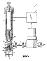
- a pressure control device 1 shown in FIG. 1 has a schematically illustrated high-pressure control valve 2 with an actuator 3.
- the high-pressure control valve serves as a counter-pressure control valve, which holds a separation column upstream on the pressure side under certain, predeterminable pressure conditions.
- On the inflow side of the high-pressure control valve there is a pressure transducer 4 which is connected to an electronic regulator. This is in turn connected to the actuator 3 of the high-pressure control valve, so that a closed control loop is present.
- the high-pressure control valve 2 has a high-pressure feed line 6 and a low-pressure side 7 with a transition to atmospheric pressure.
- a corresponding “back pressure” is set on its high-pressure side, where the packing column (not shown here) is also located.
- the working pressures can be a few hundred bar, for example up to 800 bar.
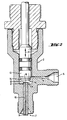
- the valve 2 shows the structure of the high-pressure control valve 2 more clearly. It has an inlet channel 8 connected to the high-pressure feed line 6 and an outlet channel 9 designed as a capillary.
- the outlet channel 9 is located within a capillary tube 10, the inlet end 11 of which forms a valve seat 12 which cooperates with a valve body 13.
- the valve body 13 is adjustable with the aid of the actuator 3 indicated in FIG. 1 according to the double arrow Pf 1.
- the valve body 13 has on its side facing the valve seat 12 a sealing washer 14 which comes into contact with the valve seat 12 when the valve is closed.
- the sealing disk 14 can be made of brightly polished metal, but is preferably made of Teflon® (polytetrafluoroethylene PTFE).
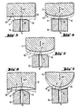
- a special feature of the high-pressure control valve 2 according to the invention now consists in the special shape of the valve body and / or the valve seat, as is shown in various embodiments according to FIGS. 3 to 7.
- an annular gap 16 is formed which extends approximately radially outwards.
- the shape of the valve seat 12 and the closing side 15 are provided such that in the closed position of the valve with the valve body in contact with the valve seat there is an annular sealing zone at the opening edge 17 of the outlet channel 9 forming a capillary.
- This comparatively narrow sealing zone leads on the one hand to a better seal in the closed position and also to better control properties of the valve, since this makes it more economical Passage conditions are present.
- Solid particles contained in the flow medium practically no longer lead to malfunctions, since jamming is largely prevented by the formation of the annular gap.
- the narrow sealing zone directly at the capillary opening edge also promotes crushing and removal of particles stuck there by the valve body 13.
- Solid particles can be ice particles, for example, resulting from the pressure reduction.
- FIG. 3 shows the preferred embodiment, where the valve body closing side 15 is flat and the valve seat opposite this side has a spherical, convex surface.
- the opening 18 of the outlet channel 9 is located centrally within this spherical surface of the valve seat 12.
- This preferred embodiment is in particular also easy to produce.
- 4 shows a flat valve seat and a valve body 13 which is convexly curved on its closing side 15.
- 5 shows an embodiment in which both the closing side 15 of the valve body 13 and the surface of the valve seat 12 are convexly curved.
- FIG. 6 shows an embodiment in which the closing side 15 of the valve body 13 is concavely curved, while the surface of the valve seat is convexly curved.
- the radius of curvature of the concave side is considerably larger than that of the convex valve seat side, so that, in turn, an outwardly widening king gap 16 results.
- FIG. 7 practically shows the inversion of the embodiment shown in FIG. 6, where the valve seat side is concave and the closing side 15 of the valve body 13 is curved convexly, the radius of curvature of the concave curvature being greater than the radius of curvature of the convex curvature of the closing side 15
- An annular gap 16 which widens radially outward is also formed here.
- a piezo converter 19 shown in FIG. 1 serves as the actuator 3 for the valve body 13. This can actively move the valve body 13 in the closing direction and release a precisely defined path length in the opening direction. High adjustment forces can be generated with small travel ranges.
- the actuator 3 for the valve body 13 In connection with the special shape of the mutually facing sides of the valve seat 12 and the valve body 13, there are particularly favorable operating conditions, it being possible in particular to work with very high pressures (for example up to 800 bar) and even solid particles in the valve area do not lead to malfunctions . Due to the actuator active in the closing direction and the comparatively narrow sealing zone, the existing solid particles are pushed away without impairing the good control properties of the valve.
- FIG. 1 and 8 show an embodiment that is expanded compared to FIG. 2 with a heater 20 arranged in the region of the valve, in particular in the region of the valve seat 12. If this heater 20 remains switched off, preparative work with dry ice discharge on the low pressure side 7 is possible, the dry ice (snow) containing the products to be isolated, which can then be collected and collected in a container 21 indicated in FIG. 8.
- the heating 20 is switched on and the heating block 22 located around the outlet duct 9 is brought to a preferably thermostatically controlled temperature of 45 ° C., for example. In this case, there is no ice formation during the expansion of the carbon dioxide mostly used in such processes.
- the measures according to the invention are: use of a piezo actuator; Special shape of the valve seat and valve body - the risk of clogging, closing or even destroying the capillary opening 18 due to ice build-up or other solid particles practically no longer exists. This means that a simplified overall structure and also increased operational reliability.
Landscapes
- Engineering & Computer Science (AREA)
- General Engineering & Computer Science (AREA)
- General Physics & Mathematics (AREA)
- Immunology (AREA)
- Health & Medical Sciences (AREA)
- Life Sciences & Earth Sciences (AREA)
- Chemical & Material Sciences (AREA)
- Analytical Chemistry (AREA)
- Biochemistry (AREA)
- General Health & Medical Sciences (AREA)
- Mechanical Engineering (AREA)
- Physics & Mathematics (AREA)
- Pathology (AREA)
- Electrically Driven Valve-Operating Means (AREA)
- Magnetically Actuated Valves (AREA)
- Lift Valve (AREA)
- Control Of Fluid Pressure (AREA)
- Temperature-Responsive Valves (AREA)
- Details Of Valves (AREA)
- Compressor (AREA)
- Fluid-Driven Valves (AREA)
Abstract
Description
Die Erfindung betrifft ein Ventil, insbesondere ein Hochdruckregelventil gemäss Oberbegriff des Patentanspruchs 1.The invention relates to a valve, in particular a high-pressure control valve according to the preamble of
Solche Hochdruckventile werden in der Chromatographie (supercritical fluid chromatography - kurz "SFC") bei Drücken bis zu einigen hundert bar eingesetzt. Sie haben dort die Aufgabe eines Gegendruck-Regelventiles, welches in einer Trennsäule einen bestimmten, vorgebbaren Druck aufrechterhält. Sie werden aber auch bei Extraktionsprozessen mit überkritischen Medien und augemein bei Systemen eingesetzt, bei denen es nötig ist, den Druckverlauf von Gasen, Flüssigkeiten und überkritischen Medien zeitlich zu kontrollieren und zu regeln.
Zur Betätigung des Ventiles ist es bereits bekannt, einen elektromagnetischen Antrieb zu verwenden, der den Ventilkörper gegen eine Federkraft in Oeffnungsrichtung bewegen kann. Bei solchen Ventilen ist ein manuelles Einstellen der Ausgangslage des Ventiles für einen bestimmten Arbeitsbereich notwendig. Dieses Einjustieren muss sehr sorgfältig erfolgen und erfordert dementsprechend viel Zeitaufwand. Auch muss die Schliessfederkraft so bemessen sein, dass einerseits ein dichtes Schliessen möglich ist und dass andererseits ein Beschädigen des Ventilsitzes bzw. einer dort befindlichen Dichtung vermieden wird. Die Schliesskraft der Feder darf höchstens so gross sein wie die zum Oeffnen zur Verfügung stehende Magnetkraft.Such high-pressure valves are used in chromatography (supercritical fluid chromatography - "SFC" for short) at pressures of up to a few hundred bar. They have the task of a counter pressure control valve which maintains a certain, predeterminable pressure in a separation column. They are also used in extraction processes with supercritical media and especially in systems where it is necessary to control and regulate the pressure of gases, liquids and supercritical media over time.
To actuate the valve, it is already known to use an electromagnetic drive which can move the valve body in the opening direction against a spring force. With such valves, manual adjustment of the starting position of the valve is necessary for a specific work area. This adjustment must be done very carefully and accordingly requires a lot of time. The closing spring force must also be dimensioned such that, on the one hand, a tight closing is possible and, on the other hand, damage to the valve seat or a seal located there is avoided. The closing force of the spring may not exceed the magnetic force available for opening.
Durch den Uebergang beim Ventil von einem Hochdruckbereich zu einem Niederdruckbereich besteht bei der Entspannung des überkritischen Mediums die Gefahr der Vereisung, die zu einer erheblichen Beeinträchtigung der Regelfunktion des Ventiles oder zur Zerstörung des Ventilsitzes führen kann. Andererseits ist es aber für ein präparatives Arbeiten erforderlich, dass Medium in fester Form (Eis) auffangen zu können. Die Funktionsbeeinträchtigung des Ventiles bei Vereisung ist darauf zurückzuführen, dass zwischen Ventilsitz und Ventilkörper Eis ansetzt und dann ein Schliessen des Ventiles dadurch behindert ist. Dies gilt analog auch für andere, im Untersuchungsmedium gegebenenfalls enthaltene Festpartikel.
Bei elektromagnetischen Regelventilen, bei denen eine Feder das Schliessen übernimmt, ist deren Federkraft auf den "Normalbetrieb" so abgestimmt, dass einerseits ein sicheres Funktionieren erreicht wird und andererseits aber Beschädigungen am Ventil vermieden werden. Diese Federeinstellung reicht aber in der Regel zum Ueberwinden der Vereisung oder sonstiger Festpartikel beim Schliessen nicht aus, so dass die Ventilregelfunktion gestört ist. Wenn der Ventilsitz und der Ventilkörper einander zugewandte und in Schliessstellung aufeinander liegende Stirnseiten haben, kann die Vereisung oder dergleichen flächig auftreten, so dass noch grössere Stellkräfte zum Wegdrücken dieser Festpartikel erforderlich wären.Due to the transition in the valve from a high pressure area to a low pressure area, when the supercritical medium is released, there is a risk of icing, which can lead to a considerable impairment of the control function of the valve or to the destruction of the valve seat. On the other hand, for preparative work it is necessary to be able to collect the medium in solid form (ice). The functional impairment of the valve in the event of icing is due to the fact that ice builds up between the valve seat and the valve body and then hinders the valve from closing. This also applies analogously to other solid particles which may be present in the examination medium.
In the case of electromagnetic control valves in which a spring takes over the closing, the spring force is adjusted to "normal operation" in such a way that on the one hand a safe functioning is achieved and on the other hand damage to the valve is avoided. However, this spring setting is usually not sufficient to overcome icing or other solid particles when closing, so that the valve control function is disturbed. If the valve seat and the valve body have end faces which face one another and which lie one on top of the other in the closed position, icing or the like can occur flatly, so that even greater actuating forces would be required to push these solid particles away.
Es sind zwar auch Nadelventile bekannt, die bei vorhandenen Festkörpern und Vereisung weniger problematisch sind, jedoch sind diese mechanisch anfällig.Needle valves are also known which are less problematic with existing solids and icing, but they are mechanically susceptible.
Um ein Vereisen des Gegendruck-Regelventiles und damit eine Funktionsbeeinträchtigung zu vermeiden, sind bereits Anordnungen mit einer Mehrstufen-, meist Zweistufenentspannung mit mehreren Ventilen bekannt, wobei das Regelventil im Bereich der ersten Entspannungsstufe angeordnet ist. Die Druckdifferenz in dieser Stufe ist so bemessen, dass ein Vereisen noch nicht auftreten kann. Allerdings erfordert diese mehrstufige Anordnung einen zusätzlichen Aufwand.
Um ein Vereisen zu vermeiden, kann im Bereich des Regelventiles auch eine Heizung vorgesehen sein. In der Praxis ist dies jedoch aus Platzgründen meist nur schwierig möglich. Zudem ist bei der gegebenen Geometrie die Wärmeübertragung meistens zu klein. Ausserdem lassen sich dann bei beheizten Ventilen präparative Arbeiten nicht durchführen.In order to avoid icing of the back pressure control valve and thus a functional impairment, arrangements with a multi-stage, usually two-stage relaxation with several valves are already known, the control valve being arranged in the region of the first expansion stage. The pressure difference at this stage is such that icing cannot yet occur. However, this multi-stage arrangement requires additional effort.
In order to avoid icing, a heater can also be provided in the area of the control valve. In practice, however, this is usually only possible with difficulty for reasons of space. In addition, with the given geometry, the heat transfer is usually too small. In addition, preparative work cannot be carried out on heated valves.
In der FR-A-2,425,559 ist ein Ventil beschrieben, das mittels eines Piezokristalls geöffnet wird. Die Schliessung des Ventils erfolgt über eine mechanische Feder. Dieses Ventil wird für Drücke unter 1 bar eingesetzt, insbesondere kommt es beim Einführen geregelter Gasströme in das Vakuum zum Einsatz. Für die Verwendung als Hochdruckregelventil für Drücke von einigen hundert bar, z.B. bis zu 800 bar, ist dieses Ventil jedoch nicht geeignet, da eine mechanische Feder derartigen Drücken nicht standhalten würde.FR-A-2,425,559 describes a valve which is opened by means of a piezo crystal. The valve is closed by a mechanical spring. This valve is used for pressures below 1 bar, in particular it is used when introducing regulated gas flows into the vacuum. For use as a high pressure control valve for pressures of several hundred bar, e.g. up to 800 bar, this valve is not suitable, as a mechanical spring would not withstand such pressures.
In der DE-A-3,608,550 ist ein Dreiwegventil beschrieben. Dieses Ventil weist ein Gehäuse auf, in welches wenigstens drei Ventilkanäle münden. Durch einen piezoelektrisch verstellbaren Dichtkörper kann der Arbeitskanal entweder mit dem einen oder mit dem anderen Ventilkanal verbunden werden. Als Gegendruck-Regelventil bei Drücken von einigen hundert bar ist dieses Dreiweg-Schaltventil nicht einsetzbar.DE-A-3,608,550 describes a three-way valve. This valve has a housing into which at least three valve channels open. The working channel can be connected to one or the other valve channel by means of a piezoelectrically adjustable sealing body. This three-way switching valve cannot be used as a back pressure control valve at pressures of several hundred bar.
Ein ähnliches Dreiweg-Schaltventil ist in der US-A-3,386,472 beschrieben. Bei diesem Ventil werden mit Hilfe eines magnetisch betätigbaren Dichtkörpers verschiedene Kanäle im Ventil durchgeschaltet. Als Hochdruckregelventil ist dieses Dreiweg-Ventil nicht einsetzbar.A similar three-way switching valve is described in US-A-3,386,472. With this valve, various channels in the valve are switched through with the aid of a magnetically actuated sealing body. This three-way valve cannot be used as a high-pressure control valve.
Aufgabe der vorliegenden Erfindung ist es, ein Hochdruckregelventil, insbesondere ein Zweiweghochdruckregelventil, zu schaffen, welches eine hohe Regelgenauigkeit über den gesamten Regelbereich hat, das darüberhinaus so ausgebildet ist, dass eine einzige Entspannungsstufe genügt, wobei ohne nachteilige Funktionsbeeinträchtigung des Regelventiles auch präparativ gearbeitet werden kann. Ausserdem soll das Durchgangsvolumen des Ventiles möglichst klein sein.The object of the present invention is to provide a high-pressure control valve, in particular a two-way high-pressure control valve, which has a high control accuracy over the entire control range, which is also designed such that a single relaxation stage is sufficient, and it is also possible to work preparatively without adversely affecting the function of the control valve . In addition, the passage volume of the valve should be as small as possible.
Zur Lösung dieser Aufgabe wird erfindungsgemäss insbesondere vorgeschlagen, dass in Schliessstellung des Ventiles mit Anlage des Ventilkörpers am Ventilsitz zwischen diesem und dem Ventilkörper ein sich von der Dichtzone am Oeffnungsrand des Auslasskanales etwa radial nach aussen erweiternder Ringspalt vorgesehen ist und dass ein in Schliessrichtung aktivierbarer Antrieb für den Ventilkörper vorgesehen ist. Diese Ausbildung der Ventilteile ergibt praktisch eine linienförmige Dichtanlage in Schliessstellung, wobei durch die Lage der Dichtzone beim Oeffnungsrand des durch eine Kapillare gebildeten Auslasskanales eine Vereisung nur in einem sehr schmalen Bereich auftreten kann. Dementsprechend ist die erforderliche Kraft zum Schliessen des Ventiles auch bei auftretender Vereisung oder anderweitigen, dazwischen befindlichen Festpartikeln erheblich reduziert. In Verbindung mit dem in Schliessrichtung aktiv arbeitenden Stellantrieb des Ventiles ergibt sich auch unter ungünstigen Bedingungen ein präzises Regelverhalten des Ventiles, da nun auch in Schliessrichtung die vom Regler vorgegebene Ventilstellung aktiv eingenommen wird. Der Schliessdruck ist somit nicht gleichbleibend für alle Fälle fest vorgegeben wie bei einem Schliessantrieb durch eine Feder, sondern die Regelung wirkt hier auch aktiv in Schliessrichtung. Unter normalen Bedingungen wird somit die Antriebskraft beim Schliessen des Ventiles nur soweit ansteigen, bis sich die vorgegebenen Druckverhältnisse einstellen, so dass die Belastung des Ventiles nur entsprechend den Erfordernissen erfolgt. Dies trägt mit zu einem störungsfreien Betrieb auch über längere Zeit bei.
Andererseits steht aber bedarfsweise auch eine wesentlich höhere Antriebskraft zur Verfügung, insbesondere wenn das Ventil bei Eisansatz oder dazwischen befindlichen Festpartikeln geschlossen werden soll, so dass auch beim präparativen Arbeiten keine Störungen auftreten.To achieve this object, it is proposed according to the invention in particular that in the closed position of the valve with the valve body resting on the valve seat between the valve seat and the valve body, an annular gap which widens radially outward from the sealing zone at the opening edge of the outlet channel is provided and that a drive which can be activated in the closing direction is provided for the valve body is provided. This design of the valve parts practically results in a linear sealing system in the closed position, whereby icing can only occur in a very narrow area due to the position of the sealing zone at the opening edge of the outlet channel formed by a capillary. Accordingly, the force required to close the valve is significantly reduced even when icing occurs or other solid particles in between. In connection with the valve actuator, which works actively in the closing direction, the valve has a precise control behavior even under unfavorable conditions, since the valve position specified by the controller is now also actively taken in the closing direction. The closing pressure is therefore not fixed in all cases, as in the case of a closing drive by a spring, but the control also acts actively in the closing direction. Under normal conditions, the driving force when the valve is closed will only increase until the specified pressure conditions occur, so that the valve is only loaded in accordance with the requirements. This also contributes to trouble-free operation over a long period of time.
On the other hand, however, a much higher driving force is available if necessary, in particular if the valve is to be closed in the case of ice build-up or solid particles located in between, so that even during preparative work none Disturbances occur.
Vorteilhafterweise ist als Ventilkörper-Schliessantrieb ein piezoelektrischer Wandler vorgesehen. Ein solcher Piezowandler als Stellantrieb für das Regelventil hat den Vorteil, dass bei den im vorliegenden Anwendungsfall vorgesehenen, kleineren Stellwegen im Bedarfsfalle, zum Beispiel bei Vereisung eine grosse Stellkraft zur Verfügung steht, die aber im Normalfall automatisch entsprechend reduziert wird. Vorteilhaft ist weiterhin, dass dieser Stellantrieb sowohl die Oeffnungsbewegung als auch die Schiiessbewegung kontrolliert, so dass der Aufbau insgesamt vereinfacht ist. Dies begünstigt auch eine kleinvolumige Bauweise, durch die das Durchgangsvolumen des Ventiles klein gehalten werden kann. Vermischungen der durchfliessenden Medien können somit verhindert werden. Auch lässt sich dadurch im Bedarfsfalle günstiger eine Heizung einsetzen. Durch die kompakte Bauweise ergeben sich grosse Wärmeaustauschflächen, welche die Wärmeübergangseigenschaften verbessern.A piezoelectric transducer is advantageously provided as the valve body closing drive. Such a piezo transducer as an actuator for the control valve has the advantage that, in the case of the smaller actuating paths provided in the present application, a large actuating force is available when needed, for example in the case of icing, but this is automatically reduced accordingly in the normal case. It is also advantageous that this actuator controls both the opening movement and the closing movement, so that the overall structure is simplified. This also favors a small-volume design, through which the passage volume of the valve can be kept small. Mixing of the media flowing through can thus be prevented. A heater can also be used more cheaply if necessary. The compact design results in large heat exchange surfaces, which improve the heat transfer properties.
Zweckmässigerweise weist der Ventilkörper eine dem Ventilsitz zugewandte, etwa plane Schliesseite und der Ventilsitz eine ballige, konvexe Oberfläche mit etwa mittig darin befindlicher Auslasskanal-Oeffnung auf. Diese bevorzugte Ausführungsform ist einfach herstellbar, wobei die ballige, abgerundete Oberfläche des Ventilsitzes zum Beispiel durch Polieren hergestellt werden kann.The valve body expediently has an approximately planar closing side facing the valve seat and the valve seat has a convex, spherical surface with an outlet channel opening located approximately in the center thereof. This preferred embodiment is simple to manufacture, the spherical, rounded surface of the valve seat being able to be produced, for example, by polishing.
Zusätzliche Ausgestaltungen der Erfindung sind in den weiteren Unteransprüchen aufgeführt. Nachstehend ist die Erfindung mit ihren wesentlichen Einzelheiten anhand der Zeichnungen noch näher erläutert.Additional embodiments of the invention are listed in the further subclaims. The invention with its essential details is explained in more detail below with reference to the drawings.
Es zeigt:
- Fig. 1 eine schematische Darstellung einer Druckregeleinrichtung,
- Fig. 2 eine Seitenansicht eines Druckregelventiles,
- Fig. 3-7 unterschiedliche Ausbildungen von zu einem Druckregelventil gehörenden Ventilsitzen und Ventilkörpern und
- Fig. 8 eine Seitenansicht eines Druckregelventiles ähnlich der Ausführungsform gemäss Fig. 2, hier jedoch mit Zusatzeinrichtung.
- 1 is a schematic representation of a pressure control device,
- 2 is a side view of a pressure control valve,
- Fig. 3-7 different designs of valve seats and valve bodies belonging to a pressure control valve and
- 8 shows a side view of a pressure control valve similar to the embodiment according to FIG. 2, but here with an additional device.
Eine in Fig. 1 gezeigte Druckregeleinrichtung 1 weist ein schematisch dargestelltes Hochdruckregelventil 2 mit einem Stellantrieb 3 auf. Das Hochdruckregelventil dient bei der Chromatographie überkritischer Strömungsmedien als Gegendruck-Regelventil, welches eine auf der Druckseite vorgeschaltete Trennsäule unter bestimmten, vorgebbaren Druckverhältnissen hält. Auf der Zuströmseite des Hochdruckregelventiles befindet sich ein Druckmesswandler 4, der mit einem elektronischen Reglers verbunden ist. Dieser ist wiederum mit dem Stellantrieb 3 des Hochdruckregelventiles verbunden, so dass ein geschlossener Regelkreis vorhanden ist.
Das Hochdruckregelventil 2 hat eine Hochdruckzuleitung 6 sowie eine Niederdruckseite 7 mit Uebergang zum Atmosphärendruck. Je nach Stellung des Hochdruckregelventiles stellt sich auf dessen Hochdruckseite, wo sich auch die hier nicht dargestellte Füllkörpersäule befindet, ein entsprechender "Staudruck" ein. Die Arbeitsdrücke können dabei einige hundert bar, zum Beispiel bis zu 800 bar betragen.A
The high-
Fig. 2 zeigt deutlicher den Aufbau des Hochdruckregelventiles 2. Es weist einen mit der Hochdruckzuleitung 6 verbundenen Einlasskanal 8 sowie einen als Kapillare ausgebildeten Auslasskanal 9 auf. Der Auslasskanal 9 befindet sich innerhalb eines Kapillarröhrchens 10, dessen Eintrittsende 11 einen Ventilsitz 12 bildet, der mit einem Ventilkörper 13 zusammenarbeitet. Der Ventilkörper 13 ist mit Hilfe des in Fig. 1 angedeuteten Stellantriebes 3 gemäss dem Doppelpfeil Pf 1 verstellbar. Der Ventilkörper 13 hat an seiner dem Ventilsitz 12 zugewandten Seite eine Dichtscheibe 14, die beim Schliessen des Ventiles in Anlage mit dem Ventilsitz 12 kommt. Die Dichtscheibe 14 kann aus blankpoliertem Metall sein, vorzugsweise ist sie aber aus Teflon® (Polytetrafluoräthylen PTFE).2 shows the structure of the high-
Eine Besonderheit des erfindungsgemässen Hochdruckregelventiles 2 besteht nun in der besonderen Formung des Ventilkörpers und/oder des Ventilsitzes, wie dies in verschiedenen Ausführungsformen gemäss Fig. 3 bis 7 gezeigt ist. Zwischen der Oberfläche des Ventilsitzes 12 und der dieser zugewandten Schliesseite 15 des Ventilkörpers 13 ist ein sich etwa radial nach aussen erweiternder Ringspalt 16 gebildet. Die Formgebung von Ventilsitz 12 und Schliesseite 15 sind dabei so vorgesehen, dass in Schliessstellung des Ventiles mit Anlage des Ventilkörpers am Ventilsitz eine ringförmige Dichtzone am Oeffnungsrand 17 des eine Kapillare bildenden Auslasskanales 9 vorhanden ist. Diese vergleichsweise schmale Dichtzone führt einerseits zu einer besseren Abdichtung in Schliessstellung und auch zu besseren Regeleigenschaften des Ventiles, da hierdurch günstigere Durchtrittsverhältnisse vorhanden sind. Auch führen im Durchströmmedium enthaltene Festpartikel dadurch praktisch nicht mehr zu Störungen, da ein Festsetzen durch die Ausbildung des Ringspaltes weitgehend verhindert wird. Auch begünstigt die schmale Dichtzone unmittelbar beim Kapillaren-Oeffnungsrand ein Zerdrücken und Abtransportieren von dort festhängenden Partikeln durch den Ventilkörper 13. Festpartikel können beispielsweise durch die Druckreduzierung entstehende Eispartikel sein.A special feature of the high-
Allen in Fig. 3 bis 7 gezeigten Ausführungsformen ist gemeinsam, dass sich der Ringspalt 16 nach aussen erweitert. Fig. 3 zeigt die bevorzugte Ausführungsform, wo die Ventilkörper-Schliesseite 15 plan ausgebildet ist und der dieser Seite gegenüberliegende Ventilsitz eine ballige, konvexe Oberfläche aufweist. Mittig innerhalb dieser balligen Oberfläche des Ventilsitzes 12 befindet sich die Oeffnung 18 des Auslasskanales 9. Diese bevorzugte Ausführungsform ist insbesondere auch einfach herstellbar.
Fig. 4 zeigt einen planen Ventilsitz und einen an seiner Schliesseite 15 konvex gewölbten Ventilkörper 13.
Fig. 5 zeigt eine Ausführungsform, bei der sowohl die Schliesseite 15 des Ventilkörpers 13 als auch die Oberfläche des Ventilsitzes 12 konvex gewölbt sind.
Fig. 6 zeigt eine Ausführungsform, bei der die Schliesseite 15 des Ventilkörpers 13 konkav gewölbt ist, während die Oberfläche des Ventilsitzes konvex gewölbt ist. Der Krümmungsradius der konkaven Seite ist hierbei wesentlich grösser als der der konvexen Ventilsitz-Seite, so dass sich wiederum ein nach aussen erweiternder Kingspalt 16 ergibt.
Fig. 7 zeigt praktisch die Umkehrung der in Fig. 6 gezeigten Ausführungsform, wo die Ventilsitz-Seite konkav und die Schliesseite 15 des Ventilkörpers 13 konvex gekrümmt sind, wobei hier der Krümmungsradius der konkaven Wölbung grösser ist als der Krümmungsradius der konvexen Wölbung der Schliesseite 15. Auch hier ist wiederum ein sich radial nach aussen erweiternder Ringspalt 16 gebildet.It is common to all of the embodiments shown in FIGS. 3 to 7 that the
4 shows a flat valve seat and a
5 shows an embodiment in which both the
Fig. 6 shows an embodiment in which the
FIG. 7 practically shows the inversion of the embodiment shown in FIG. 6, where the valve seat side is concave and the
Als Stellantrieb 3 für den Ventilkörper 13 dient ein in Fig. 1 gezeigter Piezowandler 19. Dieser kann den Ventilkörper 13 in Schliessrichtung aktiv bewegen und in Oeffnungsrichtung eine genau definierte Weglänge freigeben. Es lassen sich dabei bei kleinen Stellwegen hohe Verstellkräfte erzeugen. In Verbindung mit der speziellen Formgebung der einander zugewandten Seiten des Ventilsitzes 12 und des Ventilkörpers 13 ergeben sich besonders günstige Betriebsverhältnisse, wobei insbesondere mit sehr hohen Drücken gearbeitet werden kann (zum Beispiel bis zu 800 bar) und wobei auch Festpartikel im Ventilbereich nicht zu Funktionsstörungen führen. Durch den in Schliessrichtung aktiven Stellantrieb und die vergleichsweise schmale Dichtzone können gegebenenfalls vor handene Festpartikel weggedrückt werden, ohne dass sie die guten Regeleigenschaften des Ventiles beeinträchtigen.
Insbesondere beim präparativen Arbeiten, wo auf der Niederdruckseite 7 des Ventiles das Medium in Form von Trockeneis ausgestossen wird, ist der vorbeschriebene Sachverhalt von erheblichem Vorteil. Setzt sich nämlich beim präparativen Arbeiten im Ventilbereich Eis an, so führt dies nicht wie bisher zu Funktionsstörungen, da einerseits durch den aktiven Schliessantrieb des Ventiles und andererseits durch die Formgebung der Ventilkörper-Schliesseite beziehungsweise des Ventilsitzes der Eisansatz überwunden werden kann, so dass keine Störungen auftreten. Es besteht somit die Möglichkeit, mit einer einzigen Entspannungsstufe auszukommen.A
In particular, in preparative work, where the medium is expelled in the form of dry ice on the low-
Die Fig. 1 und 8 zeigen eine gegenüber Fig. 2 erweiterte Ausbildung mit einer im Bereich des Ventiles, insbesondere im Bereich des Ventilsitzes 12 angeordneten Heizung 20. Bleibt diese Heizung 20 ausgeschaltet, so ist ein präparatives Arbeiten mit Trockeneisausstoss auf der Niederdruckseite 7 möglich, wobei das Trockeneis (Schnee) die zu isolierenden Produkte enthält, die dann in einem in Fig. 8 angedeuteten Behälter 21 aufgefangen und gesammelt werden können. Zur analytischen Mess-Chromatographie wird die Heizung 20 eingeschaltet und der um den Auslasskanal 9 herum befindliche Heizblock 22 wird beispielsweise auf eine vorzugsweise thermostatisch geregelte Temperatur von 45°C gebracht. In diesem Falle erfolgt keine Eisbildung bei der Entspannung des bei solchen Verfahren meist verwendeten Kohlendioxids.1 and 8 show an embodiment that is expanded compared to FIG. 2 with a
Insgesamt ist durch die erfindungsgemässen Massnahmen - Verwendung eines PiezoStellantriebes; spezielle Formgebung von Ventilsitz und Ventilkörper - die Gefahr des Verstopfens, Verschliessens oder gar Zerstörens der Kapillaröffnung 18 durch Eisansatz oder andere Festpartikel praktisch nicht mehr vorhanden. Dadurch ist u.a. ein vereinfachter Gesamtaufbau und auch eine höhere Betriebssicherheit gegeben.Overall, the measures according to the invention are: use of a piezo actuator; Special shape of the valve seat and valve body - the risk of clogging, closing or even destroying the
Alle in der Beschreibung, den Ansprüchen und der Zeichnung dargestellten Merkmale können sowohl einzeln als auch in beliebiger Kombination miteinander erfindungswesentlich sein.All the features shown in the description, the claims and the drawing can be essential to the invention both individually and in any combination with one another.
Claims (11)
Applications Claiming Priority (2)
| Application Number | Priority Date | Filing Date | Title |
|---|---|---|---|
| CH4017/89 | 1989-11-08 | ||
| CH401789 | 1989-11-08 |
Publications (2)
| Publication Number | Publication Date |
|---|---|
| EP0427671A1 true EP0427671A1 (en) | 1991-05-15 |
| EP0427671B1 EP0427671B1 (en) | 1994-07-27 |
Family
ID=4268260
Family Applications (1)
| Application Number | Title | Priority Date | Filing Date |
|---|---|---|---|
| EP90810830A Expired - Lifetime EP0427671B1 (en) | 1989-11-08 | 1990-10-30 | Valve |
Country Status (7)
| Country | Link |
|---|---|
| US (1) | US5224510A (en) |
| EP (1) | EP0427671B1 (en) |
| JP (1) | JPH03172688A (en) |
| AT (1) | ATE109281T1 (en) |
| DE (1) | DE59006590D1 (en) |
| DK (1) | DK0427671T3 (en) |
| ES (1) | ES2057509T3 (en) |
Cited By (4)
| Publication number | Priority date | Publication date | Assignee | Title |
|---|---|---|---|---|
| EP0884511A2 (en) * | 1997-06-09 | 1998-12-16 | Bürkert Werke GmbH & Co. | Miniaturized valve device |
| EP1353060A1 (en) * | 2002-04-12 | 2003-10-15 | Hydraulik-Ring Gmbh | Pressure limiting valve for fuel injection devices |
| WO2010078260A1 (en) * | 2008-12-29 | 2010-07-08 | Graco Minnesota Inc. | Noise reduced air pressure relief valve |
| CN113939678A (en) * | 2019-06-05 | 2022-01-14 | 株式会社佐竹 | Piezoelectric actuator, piezoelectric valve, and method for manufacturing piezoelectric actuator |
Families Citing this family (28)
| Publication number | Priority date | Publication date | Assignee | Title |
|---|---|---|---|---|
| DE4411569C1 (en) * | 1994-04-02 | 1995-07-20 | Itw Dynatec Gmbh Klebetechnik | Application head metering flowing medium |
| US5630440A (en) * | 1995-02-21 | 1997-05-20 | Applied Power Inc. | Piezo composite sheet actuated valve |
| US5593134A (en) * | 1995-02-21 | 1997-01-14 | Applied Power Inc. | Magnetically assisted piezo-electric valve actuator |
| DE19538791C2 (en) * | 1995-10-18 | 1998-04-09 | Daimler Benz Ag | Piezo control valve for fuel injection systems of internal combustion engines |
| DE19539589C2 (en) * | 1995-10-25 | 1999-01-28 | Boesl Ulrich Priv Doz Dr | Pulsed valve for coupling a gas chromatography capillary to a secondary trace analyzer using a supersonic jet |
| JP3580645B2 (en) * | 1996-08-12 | 2004-10-27 | 忠弘 大見 | Pressure type flow controller |
| US5907107A (en) * | 1997-09-23 | 1999-05-25 | Welker Engineering Company | Heated instrument regulator tip |
| FR2782557B1 (en) * | 1998-08-21 | 2000-10-20 | Armines Ass Pour La Rech Et Le | METHOD AND DEVICE FOR TAKING MICRO SAMPLES OF A PRESSURIZED FLUID CONTAINED IN A CONTAINER |
| JP4668480B2 (en) * | 2001-08-31 | 2011-04-13 | 株式会社不二工機 | Motorized valve |
| AU2002953538A0 (en) * | 2002-12-23 | 2003-01-16 | Pickering, Graham | Clean line heated valve |
| JP4195819B2 (en) * | 2003-01-17 | 2008-12-17 | 忠弘 大見 | Method of controlling flow rate of hydrogen fluoride gas and flow control device for hydrogen fluoride gas used therefor |
| FR2853414B1 (en) * | 2003-04-01 | 2005-12-09 | Armines Ass Pour La Rech Et Le | METHOD AND DEVICE FOR PREDICTING MICRO SAMPLES FROM A PRESSURIZED FLUID CONTAINED IN A CONTAINER |
| DE102004025000A1 (en) * | 2004-05-21 | 2005-12-08 | Bayer Technology Services Gmbh | Process for the preparation of chemical and pharmaceutical products with integrated multi-column chromatography |
| US7471882B2 (en) * | 2005-09-16 | 2008-12-30 | Welker, Inc. | Heated regulator with removable heat inducer and fluid heater and methods of use |
| DE102006013512A1 (en) * | 2006-03-23 | 2007-09-27 | Siemens Ag | Fluid metering device and system for fluid metering |
| EP2317310B1 (en) * | 2009-10-28 | 2017-04-26 | Jasco Corporation | Pressure control apparatus for supercritical fluid |
| GB2517310B (en) * | 2012-03-07 | 2020-05-06 | Waters Technologies Corp | Regulator for improved thermal and pressure control for chromatography |
| US9766214B2 (en) | 2012-11-28 | 2017-09-19 | Shimadzu Corporation | Supercritical fluid processing device |
| US9910019B2 (en) | 2013-09-02 | 2018-03-06 | Shimadzu Corporation | Pressure control valve and supercritical fluid chromatograph |
| DE102013220584A1 (en) * | 2013-10-11 | 2015-04-16 | Robert Bosch Gmbh | control valve |
| JP6475950B2 (en) * | 2014-10-29 | 2019-02-27 | 株式会社フジキン | Heating device for fluid controller and fluid control device |
| US9717455B2 (en) * | 2015-03-31 | 2017-08-01 | Empire Technology Development Llc | Portable flow meter for low volume applications |
| US9980672B2 (en) | 2015-07-16 | 2018-05-29 | Empire Technology Development Llc | Single-chambered sweat rate monitoring sensor |
| US10665430B2 (en) * | 2016-07-11 | 2020-05-26 | Tokyo Electron Limited | Gas supply system, substrate processing system and gas supply method |
| US11384860B2 (en) * | 2017-05-08 | 2022-07-12 | Changzhou Mingseal Robot Technology Co., Ltd. | Fluid micro-injection device and flow channel assembly thereof |
| US11435324B2 (en) * | 2017-09-15 | 2022-09-06 | Shimadzu Corporation | Supercritical fluid apparatus |
| KR102233466B1 (en) * | 2018-10-02 | 2021-03-31 | 세메스 주식회사 | Apparatus for treating subastrate and safety valve thereof |
| JP6964889B2 (en) * | 2019-04-12 | 2021-11-10 | フロンティア・ラボ株式会社 | Column connector |
Citations (3)
| Publication number | Priority date | Publication date | Assignee | Title |
|---|---|---|---|---|
| US3386472A (en) * | 1965-03-25 | 1968-06-04 | Leeds & Northrup Co | Valves for gas chromatography |
| FR2425599A1 (en) * | 1978-05-10 | 1979-12-07 | Commissariat Energie Atomique | Fluid flow control valve - uses voltage applied across piezoelectric element to lift valve member off seat |
| DE3608550A1 (en) * | 1986-03-14 | 1987-09-17 | Festo Kg | Piezoelectrically actuated valve |
Family Cites Families (8)
| Publication number | Priority date | Publication date | Assignee | Title |
|---|---|---|---|---|
| US3415427A (en) * | 1966-08-30 | 1968-12-10 | United Steel Companies Ltd | Nozzle and stopper assemblies for teeming liquid metal |
| DE1650271B1 (en) * | 1966-11-25 | 1970-04-23 | Oederlin Cie Ag | Throttle valve with a seal |
| AT327335B (en) * | 1968-01-29 | 1976-01-26 | Boehler & Co Ag Geb | DEVICE FOR SEALING SPINDLES, ESPECIALLY FOR VALVES FOR LIQUID METALS, SUCH AS LIQUID SODIUM, E.G. IN NUCLEAR REACTORS |
| US4316600A (en) * | 1980-06-04 | 1982-02-23 | Parise & Sons, Inc. | Fast acting, nonrepairable plastic on/off valve |
| DE3039915A1 (en) * | 1980-10-23 | 1982-05-27 | Robert Bosch Gmbh, 7000 Stuttgart | ELECTRICALLY CONTROLLABLE VALVE DEVICE |
| DE3502276A1 (en) * | 1985-01-24 | 1986-07-24 | Wabco Westinghouse Fahrzeugbremsen GmbH, 3000 Hannover | DEVICE FOR CONTINUOUSLY CONTROLLING A SOLENOID VALVE DESIGNED NORMALLY FOR DISCONTINUOUS OPERATION |
| SE456597B (en) * | 1987-02-12 | 1988-10-17 | Scandot System Ab | DEVICE FOR A VALVE ARRANGEMENT FOR THE EXHAUST OF LIQUID BY A SCRIPLINE PRINTER |
| US4928920A (en) * | 1989-05-18 | 1990-05-29 | Laminar Fluid Controls, Inc. | Finely-adjustable flow control valve |
-
1990
- 1990-10-30 DK DK90810830.1T patent/DK0427671T3/en active
- 1990-10-30 EP EP90810830A patent/EP0427671B1/en not_active Expired - Lifetime
- 1990-10-30 AT AT90810830T patent/ATE109281T1/en not_active IP Right Cessation
- 1990-10-30 ES ES90810830T patent/ES2057509T3/en not_active Expired - Lifetime
- 1990-10-30 DE DE59006590T patent/DE59006590D1/en not_active Expired - Fee Related
- 1990-10-31 US US07/606,405 patent/US5224510A/en not_active Expired - Fee Related
- 1990-11-08 JP JP2303733A patent/JPH03172688A/en active Pending
Patent Citations (3)
| Publication number | Priority date | Publication date | Assignee | Title |
|---|---|---|---|---|
| US3386472A (en) * | 1965-03-25 | 1968-06-04 | Leeds & Northrup Co | Valves for gas chromatography |
| FR2425599A1 (en) * | 1978-05-10 | 1979-12-07 | Commissariat Energie Atomique | Fluid flow control valve - uses voltage applied across piezoelectric element to lift valve member off seat |
| DE3608550A1 (en) * | 1986-03-14 | 1987-09-17 | Festo Kg | Piezoelectrically actuated valve |
Cited By (6)
| Publication number | Priority date | Publication date | Assignee | Title |
|---|---|---|---|---|
| EP0884511A2 (en) * | 1997-06-09 | 1998-12-16 | Bürkert Werke GmbH & Co. | Miniaturized valve device |
| EP0884511A3 (en) * | 1997-06-09 | 1999-04-07 | Bürkert Werke GmbH & Co. | Miniaturized valve device |
| US6076555A (en) * | 1997-06-09 | 2000-06-20 | Burkert Werke Gmbh & Co. | Miniaturized valve mechanism |
| EP1353060A1 (en) * | 2002-04-12 | 2003-10-15 | Hydraulik-Ring Gmbh | Pressure limiting valve for fuel injection devices |
| WO2010078260A1 (en) * | 2008-12-29 | 2010-07-08 | Graco Minnesota Inc. | Noise reduced air pressure relief valve |
| CN113939678A (en) * | 2019-06-05 | 2022-01-14 | 株式会社佐竹 | Piezoelectric actuator, piezoelectric valve, and method for manufacturing piezoelectric actuator |
Also Published As
| Publication number | Publication date |
|---|---|
| ATE109281T1 (en) | 1994-08-15 |
| ES2057509T3 (en) | 1994-10-16 |
| US5224510A (en) | 1993-07-06 |
| EP0427671B1 (en) | 1994-07-27 |
| DE59006590D1 (en) | 1994-09-01 |
| DK0427671T3 (en) | 1994-11-28 |
| JPH03172688A (en) | 1991-07-26 |
Similar Documents
| Publication | Publication Date | Title |
|---|---|---|
| EP0427671B1 (en) | Valve | |
| EP0872674B1 (en) | Pressure-compensated solenoid valve | |
| DE19826076C1 (en) | Double safety valve for the gas inlet to a gas heating system | |
| DE2818633C2 (en) | ||
| DE69502086T2 (en) | Control device for a valve | |
| EP0067403A1 (en) | Ball valve | |
| LU84377A1 (en) | ADJUSTABLE THROTTLE VALVE | |
| DE69303778T2 (en) | Servo-controlled valve | |
| EP0041247B1 (en) | Pilot-operated device for load-independent flow control | |
| EP0882916A1 (en) | Valve assembly | |
| EP0491652B1 (en) | Device for shifting a valve body with a piezoelectric element for a valve and use of it | |
| WO2002023036A1 (en) | Valve configuration for control valves | |
| CH622326A5 (en) | ||
| DE2416286A1 (en) | Self-closing fitting with piston valve - which moves longitudinally in a housing and a main valve seat in its bottom | |
| EP0111617A1 (en) | Fluid-pressure actuated activating device with locking member | |
| DE3006298C2 (en) | Electro-hydraulic switching device | |
| EP2561211B1 (en) | Pressure control valve device for supplying corrosive media | |
| DE29618080U1 (en) | Pressure regulator | |
| DE3206107A1 (en) | Pressure control valve | |
| EP3722643B1 (en) | Mixing valve | |
| DE2011535A1 (en) | Valve for pressure medium | |
| DE3520554A1 (en) | PNEUMATIC PRESSURE SWITCH FOR CONTROLLING THE COMPRESSED AIR CHAMBER OF MEDIUM-FLOWED FITTINGS | |
| DE1926637B2 (en) | SEAL FOR A CHANGEOVER VALVE WITH A MAGNETICALLY RELEASABLE AUXILIARY VALVE | |
| DE3620242A1 (en) | Pilot valve, in particular 3/2 way valve | |
| DE3045752A1 (en) | FITTING WITH ROTATING LOCK |
Legal Events
| Date | Code | Title | Description |
|---|---|---|---|
| PUAI | Public reference made under article 153(3) epc to a published international application that has entered the european phase |
Free format text: ORIGINAL CODE: 0009012 |
|
| 17P | Request for examination filed |
Effective date: 19901102 |
|
| AK | Designated contracting states |
Kind code of ref document: A1 Designated state(s): AT BE CH DE DK ES FR GB GR IT LI LU NL SE |
|
| 17Q | First examination report despatched |
Effective date: 19930224 |
|
| GRAA | (expected) grant |
Free format text: ORIGINAL CODE: 0009210 |
|
| AK | Designated contracting states |
Kind code of ref document: B1 Designated state(s): AT BE CH DE DK ES FR GB GR IT LI LU NL SE |
|
| REF | Corresponds to: |
Ref document number: 109281 Country of ref document: AT Date of ref document: 19940815 Kind code of ref document: T |
|
| ET | Fr: translation filed | ||
| REF | Corresponds to: |
Ref document number: 59006590 Country of ref document: DE Date of ref document: 19940901 |
|
| REG | Reference to a national code |
Ref country code: ES Ref legal event code: FG2A Ref document number: 2057509 Country of ref document: ES Kind code of ref document: T3 |
|
| ITF | It: translation for a ep patent filed | ||
| REG | Reference to a national code |
Ref country code: DK Ref legal event code: T3 |
|
| GBT | Gb: translation of ep patent filed (gb section 77(6)(a)/1977) |
Effective date: 19941028 |
|
| REG | Reference to a national code |
Ref country code: GR Ref legal event code: FG4A Free format text: 3013203 |
|
| EAL | Se: european patent in force in sweden |
Ref document number: 90810830.1 |
|
| PLBE | No opposition filed within time limit |
Free format text: ORIGINAL CODE: 0009261 |
|
| STAA | Information on the status of an ep patent application or granted ep patent |
Free format text: STATUS: NO OPPOSITION FILED WITHIN TIME LIMIT |
|
| 26N | No opposition filed | ||
| ITTA | It: last paid annual fee | ||
| REG | Reference to a national code |
Ref country code: CH Ref legal event code: PFA Free format text: CIBA-GEIGY AG TRANSFER- NOVARTIS AG |
|
| REG | Reference to a national code |
Ref country code: GB Ref legal event code: 732E |
|
| NLS | Nl: assignments of ep-patents |
Owner name: NOVARTIS AG |
|
| REG | Reference to a national code |
Ref country code: FR Ref legal event code: TP |
|
| PGFP | Annual fee paid to national office [announced via postgrant information from national office to epo] |
Ref country code: FR Payment date: 19970806 Year of fee payment: 8 |
|
| PGFP | Annual fee paid to national office [announced via postgrant information from national office to epo] |
Ref country code: NL Payment date: 19970814 Year of fee payment: 8 |
|
| PGFP | Annual fee paid to national office [announced via postgrant information from national office to epo] |
Ref country code: SE Payment date: 19970815 Year of fee payment: 8 |
|
| PGFP | Annual fee paid to national office [announced via postgrant information from national office to epo] |
Ref country code: GR Payment date: 19970818 Year of fee payment: 8 |
|
| PGFP | Annual fee paid to national office [announced via postgrant information from national office to epo] |
Ref country code: DK Payment date: 19970819 Year of fee payment: 8 |
|
| PGFP | Annual fee paid to national office [announced via postgrant information from national office to epo] |
Ref country code: AT Payment date: 19970821 Year of fee payment: 8 |
|
| PGFP | Annual fee paid to national office [announced via postgrant information from national office to epo] |
Ref country code: DE Payment date: 19970823 Year of fee payment: 8 |
|
| PGFP | Annual fee paid to national office [announced via postgrant information from national office to epo] |
Ref country code: GB Payment date: 19970903 Year of fee payment: 8 |
|
| PGFP | Annual fee paid to national office [announced via postgrant information from national office to epo] |
Ref country code: LU Payment date: 19970910 Year of fee payment: 8 |
|
| PGFP | Annual fee paid to national office [announced via postgrant information from national office to epo] |
Ref country code: CH Payment date: 19970916 Year of fee payment: 8 |
|
| PGFP | Annual fee paid to national office [announced via postgrant information from national office to epo] |
Ref country code: ES Payment date: 19971015 Year of fee payment: 8 |
|
| PGFP | Annual fee paid to national office [announced via postgrant information from national office to epo] |
Ref country code: BE Payment date: 19971211 Year of fee payment: 8 |
|
| REG | Reference to a national code |
Ref country code: ES Ref legal event code: PC2A |
|
| PG25 | Lapsed in a contracting state [announced via postgrant information from national office to epo] |
Ref country code: LU Free format text: LAPSE BECAUSE OF NON-PAYMENT OF DUE FEES Effective date: 19981030 Ref country code: GB Free format text: LAPSE BECAUSE OF NON-PAYMENT OF DUE FEES Effective date: 19981030 Ref country code: DK Free format text: LAPSE BECAUSE OF NON-PAYMENT OF DUE FEES Effective date: 19981030 Ref country code: AT Free format text: LAPSE BECAUSE OF NON-PAYMENT OF DUE FEES Effective date: 19981030 |
|
| PG25 | Lapsed in a contracting state [announced via postgrant information from national office to epo] |
Ref country code: SE Free format text: LAPSE BECAUSE OF NON-PAYMENT OF DUE FEES Effective date: 19981031 Ref country code: LI Free format text: LAPSE BECAUSE OF NON-PAYMENT OF DUE FEES Effective date: 19981031 Ref country code: GR Free format text: LAPSE BECAUSE OF NON-PAYMENT OF DUE FEES Effective date: 19981031 Ref country code: ES Free format text: LAPSE BECAUSE OF NON-PAYMENT OF DUE FEES Effective date: 19981031 Ref country code: CH Free format text: LAPSE BECAUSE OF NON-PAYMENT OF DUE FEES Effective date: 19981031 Ref country code: BE Free format text: LAPSE BECAUSE OF NON-PAYMENT OF DUE FEES Effective date: 19981031 |
|
| BERE | Be: lapsed |
Owner name: NOVARTIS A.G. Effective date: 19981031 |
|
| PG25 | Lapsed in a contracting state [announced via postgrant information from national office to epo] |
Ref country code: NL Free format text: LAPSE BECAUSE OF NON-PAYMENT OF DUE FEES Effective date: 19990501 |
|
| REG | Reference to a national code |
Ref country code: CH Ref legal event code: PL |
|
| GBPC | Gb: european patent ceased through non-payment of renewal fee |
Effective date: 19981030 |
|
| EUG | Se: european patent has lapsed |
Ref document number: 90810830.1 |
|
| PG25 | Lapsed in a contracting state [announced via postgrant information from national office to epo] |
Ref country code: FR Free format text: LAPSE BECAUSE OF NON-PAYMENT OF DUE FEES Effective date: 19990630 |
|
| NLV4 | Nl: lapsed or anulled due to non-payment of the annual fee |
Effective date: 19990501 |
|
| REG | Reference to a national code |
Ref country code: FR Ref legal event code: ST |
|
| PG25 | Lapsed in a contracting state [announced via postgrant information from national office to epo] |
Ref country code: DE Free format text: LAPSE BECAUSE OF NON-PAYMENT OF DUE FEES Effective date: 19990803 |
|
| REG | Reference to a national code |
Ref country code: DK Ref legal event code: EBP |
|
| REG | Reference to a national code |
Ref country code: ES Ref legal event code: FD2A Effective date: 19991113 |
|
| PG25 | Lapsed in a contracting state [announced via postgrant information from national office to epo] |
Ref country code: IT Free format text: LAPSE BECAUSE OF NON-PAYMENT OF DUE FEES;WARNING: LAPSES OF ITALIAN PATENTS WITH EFFECTIVE DATE BEFORE 2007 MAY HAVE OCCURRED AT ANY TIME BEFORE 2007. THE CORRECT EFFECTIVE DATE MAY BE DIFFERENT FROM THE ONE RECORDED. Effective date: 20051030 |