EP0427662B1 - Hypsometer with controlled heating specially for use in meteorologic radio-sondes - Google Patents
Hypsometer with controlled heating specially for use in meteorologic radio-sondes Download PDFInfo
- Publication number
- EP0427662B1 EP0427662B1 EP90810399A EP90810399A EP0427662B1 EP 0427662 B1 EP0427662 B1 EP 0427662B1 EP 90810399 A EP90810399 A EP 90810399A EP 90810399 A EP90810399 A EP 90810399A EP 0427662 B1 EP0427662 B1 EP 0427662B1
- Authority
- EP
- European Patent Office
- Prior art keywords
- hypsometer
- vessel
- temperature
- heating
- boiling
- Prior art date
- Legal status (The legal status is an assumption and is not a legal conclusion. Google has not performed a legal analysis and makes no representation as to the accuracy of the status listed.)
- Expired - Lifetime
Links
Images
Classifications
-
- G—PHYSICS
- G05—CONTROLLING; REGULATING
- G05D—SYSTEMS FOR CONTROLLING OR REGULATING NON-ELECTRIC VARIABLES
- G05D23/00—Control of temperature
- G05D23/19—Control of temperature characterised by the use of electric means
- G05D23/20—Control of temperature characterised by the use of electric means with sensing elements having variation of electric or magnetic properties with change of temperature
- G05D23/24—Control of temperature characterised by the use of electric means with sensing elements having variation of electric or magnetic properties with change of temperature the sensing element having a resistance varying with temperature, e.g. a thermistor
- G05D23/2401—Control of temperature characterised by the use of electric means with sensing elements having variation of electric or magnetic properties with change of temperature the sensing element having a resistance varying with temperature, e.g. a thermistor using a heating element as a sensing element
-
- G—PHYSICS
- G01—MEASURING; TESTING
- G01L—MEASURING FORCE, STRESS, TORQUE, WORK, MECHANICAL POWER, MECHANICAL EFFICIENCY, OR FLUID PRESSURE
- G01L11/00—Measuring steady or quasi-steady pressure of a fluid or a fluent solid material by means not provided for in group G01L7/00 or G01L9/00
- G01L11/002—Measuring steady or quasi-steady pressure of a fluid or a fluent solid material by means not provided for in group G01L7/00 or G01L9/00 by thermal means, e.g. hypsometer
-
- G—PHYSICS
- G05—CONTROLLING; REGULATING
- G05D—SYSTEMS FOR CONTROLLING OR REGULATING NON-ELECTRIC VARIABLES
- G05D23/00—Control of temperature
- G05D23/19—Control of temperature characterised by the use of electric means
- G05D23/1927—Control of temperature characterised by the use of electric means using a plurality of sensors
- G05D23/193—Control of temperature characterised by the use of electric means using a plurality of sensors sensing the temperaure in different places in thermal relationship with one or more spaces
- G05D23/1931—Control of temperature characterised by the use of electric means using a plurality of sensors sensing the temperaure in different places in thermal relationship with one or more spaces to control the temperature of one space
Landscapes
- Engineering & Computer Science (AREA)
- Physics & Mathematics (AREA)
- General Physics & Mathematics (AREA)
- Automation & Control Theory (AREA)
- Remote Sensing (AREA)
- Control Of Temperature (AREA)
- Investigating Or Analyzing Materials Using Thermal Means (AREA)
- Cookers (AREA)
- Measuring Temperature Or Quantity Of Heat (AREA)
- Medicinal Preparation (AREA)
Abstract
Description
Die vorliegende Erfindung betrifft Hypsometer Ansprüche 1, 3 mit geregelter Heizung, insbesondere für die Verwendung in meteorologischen Radiosonden, mit einem offenen Siedegefäss, das aus einem die Messflüssigkeit enthaltenden Kolben und einem an den Kolben anschliessenden Hals besteht, wobei der Gefässkolben einen in die Messflüssigkeit eintauchenden elektrischen Heizwiderstand und einen die Siedepunkt-Temperatur erfassenden Temperaturfühler aufweist, und wobei ein adaptives Regelsystem vorgesehen ist, welches die Heizleistung auf einen der jeweiligen Siedepunkt-Temperatur angepassten Wert regelt.The present invention relates to
Das Hypsometer ist ein Siedepunkttemperatur-Barometer, mit dem über den Zusammenhang zwischen Sättigungsdampfdruck und Siedetemperatur der Luftdruck bestimmt werden kann. Dabei ändert sich die Siedetemperatur logarithmisch mit dem Druck, was in Anwendungen mit grossem Druck-Messbereich den Vorteil bietet, dass bei gleichbleibender absoluter Messgenauigkeit der Siedetemperatur die relative Druck-Messgenauigkeit gleich bleibt. Meteorologische Radiosonden durchfliegen bei ihrem Aufstieg in 35 km Höhe einen Druckbereich von 1000 hPa bis 5 hPa. Deshalb eignet sich das Hypsometer besser als die im allgemeinen verwendeten Aneroid-Barometer. Ein weiterer wesentlicher Vorteil des Hypsometers gegenüber dem Aneroid-Barometer ist der, dass ersteres nicht individuell geeicht werden muss, da der Zusammenhang zwischen Druck und Siedetemperatur genügend genau bekannt ist. Sonden, die nicht geeicht werden müssen, können ohne weiteres wieder verwendet werden, nachdem sie gefunden wurden. Dies ist auch aus ökologischen Gründen sinnvoll. Es wurde deshalb schon vor Jahrzehnten vorgeschlagen, Radiosonden mit Hypsometern auszurüsten.The hypsometer is a boiling point barometer with which the air pressure can be determined via the relationship between saturation vapor pressure and boiling temperature. The boiling temperature changes logarithmically with the pressure, which offers the advantage in applications with a large pressure measurement range that the relative pressure measurement accuracy remains the same with the absolute measurement accuracy of the boiling temperature remaining the same. Meteorological radio probes fly through a pressure range of 1000 hPa to 5 hPa when they ascend at a height of 35 km. The hypsometer is therefore more suitable than the aneroid barometers generally used. Another major advantage of the hypsometer over the aneroid barometer is that the former is not individually calibrated must be known because the relationship between pressure and boiling temperature is known with sufficient accuracy. Probes that do not need to be calibrated can be easily reused after they are found. This also makes sense for ecological reasons. It was therefore proposed decades ago to equip radio probes with hypsometers.
Geheizte Hypsometer verwenden eine Flüssigkeit, deren Siedetemperatur höher ist als die Umgebungstemperatur, z.B. Wasser. Die Heizleistung darf nicht gross sein, da sie aus mitfliegenden Batterien aufgebracht werden muss. Es ist deshalb eine geringe Flüssigkeitsmenge anzustreben. Um jedoch mit einer geringen Flüssigkeitsmenge eine ausreichend lange Betriebsdauer zu erreichen, darf während des Betriebs des Hypsometers keine Flüssigkeit durch Kondensation des Dampfes ausserhalb des Siedegefässes verloren gehen. Andererseits muss die Heizleistung stets so gross sein, dass der Siedevorgang im ganzen Druckbereich aufrechterhalten wird. Um diese Forderungen zu erfüllen, ist eine geeignete Regelung der Heizleistung vorzusehen.Heated hypsometers use a liquid whose boiling temperature is higher than the ambient temperature, e.g. Water. The heating power must not be high, since it has to be applied from the batteries that fly along. A small amount of liquid should therefore be aimed for. However, in order to achieve a sufficiently long operating time with a small amount of liquid, no liquid may be lost due to condensation of the steam outside the boiling vessel during the operation of the hypsometer. On the other hand, the heating output must always be so high that the boiling process is maintained in the entire pressure range. In order to meet these requirements, a suitable regulation of the heating power must be provided.
Bei einem bekannten Hypsometer der eingangs genannten Art (Lueger, Lexikon der Technik, 4. Auflage, 1968, Band 13, Seite 456) ist eine Regelung der Heizleistung mit einem Thermostaten vorgesehen, dessen Temperaturmesspunkt sich im Dampfausdehnungsraum befindet. Diese Regelung funktioniert jedoch nur in einem engen Bereich der Siedetemperatur, in dem mit einer konstanten Solltemperatur am Temperaturmesspunkt des Thermostaten gearbeitet werden kann. Sobald die Siedetemperatur diesen Bereich über- oder unterschreitet, fällt die am Messpunkt herrschende Temperatur aus dem Regelbereich des Thermostaten, so dass die Heizleistung bei weiter abnehmender Siedetemperatur stets voll eingeschaltet und bei weiter zunehmender Siedetemperatur ganz abgeschaltet ist. In diesen Phasen ist jedoch ein ordentlicher Betrieb des Hypsometers nicht mehr gewährleistet, weil die genannten Randbedingungen dafür nicht mehr erfüllt sind. Dieses Hypsometer eignet sich daher zwar for einen stationären Betrieb, nicht aber für die Verwendung in meteorologischen Radiosonden, bei deren Flug die Siedetemperatur sich von 100 °C bis auf wenige Grad ändern kann.In a known hypsometer of the type mentioned at the beginning (Lueger, Lexikon der Technik, 4th edition, 1968,
Die zum Sieden nötige Heizleistung nimmt mit zunehmender Höhe ab, da einerseits der Luftdruck und damit die Siedetemperatur sinkt und andererseits mit sinkendem Luftdruck die Wärmeleitfähigkeit der Luft und damit der Wärmeverlust geringer wird. Zwar funktioniert das Hypsometer auch dann einwandfrei, wenn dauernd die for den Bodendruck notwendige grosse Heizleistung zugeführt wird. Der Grund für diese Toleranz des Instruments ist die grosse Verdampfungswärme von Wasser. Die dauernde Zufuhr von zuviel Heizleistung ist aber nicht nur wegen der damit verbundenen Gefahr eines übermässigen Flüssigkeitsverlustes, sondern vor allem auch aus Versorgungsgründen unerwünscht, da die Energie aus einer Batterie aufgebracht werden muss. Neben den Kosten ist besonders das Gewicht von unnötig grossen Batterien bei Radiosondenanwendungen störend.The heating power required for boiling decreases with increasing altitude, because on the one hand the air pressure and thus the boiling temperature decrease and on the other hand the thermal conductivity of the air and thus the heat loss decrease with decreasing air pressure. The hypsometer works perfectly even if the large heating power required for the ground pressure is continuously supplied. The reason for this tolerance of the instrument is the great heat of vaporization of water. The continuous supply of too much heating power is undesirable not only because of the associated risk of excessive loss of fluid, but above all also for reasons of supply, since the energy is applied from a battery got to. In addition to the costs, the weight of unnecessarily large batteries is particularly disruptive in radio probe applications.
Die US-A-3276262 beschreibt ein Hypsometer, das mit einem adaptiven Regelsystem ausgerüstet ist, welches den Heizstrom so regelt, dass die Verdampfungsrate unabhängig von dem Druck und der Temperatur der Umgebung auf einen verhältnismässig konstanten Wert eingestellt wird. Auf diese Weise findet eine gewisse Anpassung der Heizleistung an die jeweilige Siedepunkt-Temperatur statt, wodurch Heizenergie gespart wird. Andererseits soll mit einer langen, an das Siedegefäss sich anschliessenden Kondensationsstrecke erreicht werden, dass die verdampfte Messflüssigkeit vollständig innerhalb des Geräts kondensiert, so dass die Flüssigkeitsmenge über eine längere Einsatzdauer des Geräts erhalten bleibt.US-A-3276262 describes a hypsometer which is equipped with an adaptive control system which controls the heating current in such a way that the evaporation rate is set to a relatively constant value regardless of the pressure and the temperature of the environment. In this way, the heating output is adapted to the respective boiling point temperature, which saves heating energy. On the other hand, a long condensation section connected to the boiling vessel is intended to ensure that the evaporated measuring liquid condenses completely within the device, so that the amount of liquid is retained over a longer period of use of the device.
Der Erfindung liegt die Aufgabe zugrunde, eine Regelung der Heizleistung vorzusehen, die es ermöglicht, die Lage der Kondensationszone im ganzen Druckbereich innerhalb des Gefässhalses zu stabilisieren und damit zugleich die Heizleistung dem jeweiligen Bedarf anzupassen.The invention has for its object to provide a control of the heating power, which makes it possible to stabilize the position of the condensation zone in the entire pressure range within the neck of the vessel and thus at the same time to adapt the heating power to the respective need.
Diese Aufgabe lässt sich bei einem Hypsometer der eingangs genannten Art dadurch lösen, dass erfindungsgemäss Mittel zur Messung des Temperaturabfalls im Gefässhals längs einer an dessen unterem Ende liegenden Messstrecke vorgesehen sind und dass eine bestimmte Temperaturdifferenz als Sollwert für die Regelung der Heizleistung dient, wobei die Regelung der Heizleistung so vorgesehen ist, daß die Lage der Kondensationszone im ganzen Druckbereich innerhalb des Gefäßhalses stabilisiert ist.This problem can be solved in a hypsometer of the type mentioned at the outset that means according to the invention are provided for measuring the temperature drop in the neck of the vessel along a measuring section located at its lower end and that a certain temperature difference serves as a setpoint for the regulation of the heating power, the regulation the heating power is provided so that the position of the condensation zone is stabilized in the entire pressure range within the neck of the vessel.
Diese Temperaturdifferenz ändert sich stark, je nachdem, ob die Kondensationszone des Dampfes unterhalb, innerhalb oder oberhalb der Messstrecke liegt. Die Lage der Kondensationszone wird durch die pro Zeiteinheit erzeugte Dampfmenge, d.h. durch das Mass der Heizleistung bestimmt. Die Temperaturdifferenz über der Messstrecke ist praktisch Null, wenn die Kondensationszone oberhalb der Messstrecke liegt. Die Regelung arbeitet deshalb vorzugsweise mit einem kleinen Sollwert der Temperaturdifferenz von z.B. 1 °C. Damit ist gewährleistet, dass sich die Kondensationszone knapp oberhalb der Messstrecke befindet, und zwar unabhängig von der jeweiligen Siedetemperatur, mit dem Ergebnis, dass im ganzen Druckbereich die Flüssigkeit mit Sicherheit siedet und der Dampf stets innerhalb des Siedegefässes kondensiert. Mit dieser Lösung in Form eines indirekten adaptiven Regelsystems lässt sich zugleich eine optimale Anpassung der Heizleistung an den jeweiligen Bedarf erzielen.This temperature difference changes greatly depending on whether the condensation zone of the steam is below, within or above the measuring section. The position of the condensation zone is determined by the amount of steam generated per unit of time, i.e. determined by the amount of heating power. The temperature difference across the measuring section is practically zero if the condensation zone is above the measuring section. The control therefore preferably works with a small setpoint of the temperature difference of e.g. 1 ° C. This ensures that the condensation zone is just above the measuring section, regardless of the respective boiling temperature, with the result that the liquid boils with certainty in the entire pressure range and the steam always condenses inside the boiling vessel. With this solution in the form of an indirect adaptive control system, the heating output can be optimally adapted to the respective requirements.
Das Hypsometer nach der US-A-3276262 weist zwar ein ähnliches Regelsystem auf, unter dessen Wirkung die Differenz der Temperaturen an zwei Messpunkten annähernd konstant bleibt. Die Anordnung der dafür vorgesehenen Temperaturfühler ist aber nicht geeignet, die Kondensationszone auf einen innerhalb des Siedegefässes liegenden Raum zu begrenzen. Ferner dient hier nicht die Temperaturdifferenz, sondern das Verhältnis der Temperaturen an den beiden Messpunkten als Sollwert für die Temperaturdifferenz nur dann näherungsweise konstant, solange sie im Vergleich zur Siedepunkt-Temperatur sehr klein ist, d.h. wenn das Temperaturverhältnis nur wenig von 1 abweicht. Diese Bedingung ist aber nur in einem verhältnismässig engen Schwankungsbereich der Siedepunkt-Temperatur erfüllt. Bei grösseren Schwankungen der Siedepunkt-Temperatur, wie sie bei einer Radiosonde auftreten, würde das Temperaturverhältnis sehr bald aus dem Regelbereich fallen. Mit einem solchen Regelsystem kann es also nicht gelingen, den Temperturabfall an der Messstrecke über einen grösseren Druckbereich konstant zu halten.The hypsometer according to US-A-3276262 does indeed have a similar control system, under the effect of which the difference in temperatures at two measuring points remains approximately constant. However, the arrangement of the temperature sensors provided for this purpose is not suitable for restricting the condensation zone to a space inside the boiling vessel. Furthermore, it is not the temperature difference that is used here, but rather the ratio of the temperatures at the two measuring points as the setpoint for the Temperature difference only approximately constant as long as it is very small compared to the boiling point temperature, ie if the temperature ratio deviates only slightly from 1. However, this condition is only met in a relatively narrow fluctuation range of the boiling point temperature. With larger fluctuations in the boiling point temperature, such as occur with a radio probe, the temperature ratio would very soon fall outside the control range. With such a control system, it is not possible to keep the temperature drop along the measuring section constant over a larger pressure range.
Wenn man davon ausgeht, dass unter Einhaltung der Randbedingungen (Aufrechterhaltung des Siedevorganges, Vermeidung von Flüssigkeitsverlust) eine genaue Regelung der Heizleistung aus messtechnischen Gründen nicht notwendig ist, lässt sich eine einfachere Lösung mit einem direkten adaptiven Regelsystem bei einem Hypsometer der eingangs genannten Art dadurch erzielen, dass als Heizwiderstand ein Thermistor mit negativem Temperaturkoeffizienten (NTC) vorgesehen ist, wobei die Regelung der Heizleistung so vorgesehen ist, daß die Lage der Kondensationszone im ganzen Druckbereich innerhalb des Gefäßhalses stabilisiert ist. Schliesst man einen derartigen Thermistor in Luft an eine Spannungsquelle an, so erwärmt er sich zunehmend bis zu seiner Zerstörung. Es ist deshalb in der Technik völlig unüblich, mit NTC-Widerständen zu heizen. Anders verhält sich der NTC- Heizwiderstand in einer siedenden Flüssigkeit. Die dem NTC- Heizwiderstand allenfalls zuviel zugeführte Heizleistung kann diesen nicht über die Siedetemperatur hinaus erwärmen. Die überschüssige Leistung wird vielmehr für das Verdampfen der Flüssigkeit verbraucht. Sinkt nun beispielsweise die Siedetemperatur wegen Abnahme des Luftdrucks, dann nimmt der Widerstandswert des Thermistors infolge seines negativen Temperaturkoeffizienten von z.B. etwa 4 %/°C zu und reduziert damit bei gleichbleibender Batteriespannung die umgesetzte Heizleistung. Damit wird über die Widerstands-Temperatur-Kennlinie die Heizleistung von der Siedetemperatur abhängig. Mit Vorteil werden die Kennlinie des Thermistors und die durch dessen Widerstandswert und die Batteriespannung bestimmte Heizleistung so gewählt, dass dem Hypsometer im ganzen Druckbereich eine um einen Sicherheitsfaktor grössere Heizleistung zugeführt wird, als zum Sieden nötig wäre. Dadurch ist trotz der durch Exemplarstreuungen entstehenden Unterschiede der Anordnung ein sicheres Sieden der Flüssigkeit in jedem Betriebszustand gewährleistet.If one assumes that an exact control of the heating power is not necessary for measurement reasons, while observing the boundary conditions (maintaining the boiling process, avoiding liquid loss), a simpler solution can be achieved with a direct adaptive control system with a hypsometer of the type mentioned at the beginning that a thermistor with a negative temperature coefficient (NTC) is provided as the heating resistor, the regulation of the heating power being provided so that the position of the condensation zone is stabilized in the entire pressure range within the neck of the vessel. If one connects such a thermistor in air to a voltage source, it heats up increasingly until it is destroyed. It is therefore completely unusual in technology to heat with NTC resistors. The NTC heating resistor behaves differently in a boiling liquid. The heating power supplied to the NTC heating resistor, if at all, too much, cannot heat it above the boiling temperature. Rather, the excess power is used to evaporate the liquid. Now, for example, the boiling temperature drops due to a decrease in air pressure, the resistance value of the thermistor increases as a result of its negative temperature coefficient of, for example, about 4% / ° C. and thus reduces the heat output when the battery voltage remains the same. The heating output is thus dependent on the boiling temperature via the resistance-temperature characteristic. The characteristic curve of the thermistor and the heating power determined by its resistance value and the battery voltage are advantageously selected so that the heating power supplied to the hypsometer in the entire pressure range is a safety factor greater than would be necessary for boiling. This ensures a safe boiling of the liquid in any operating condition, despite the differences in the arrangement caused by specimen scatter.
Diese Lösung mit einem direkten adaptiven Regelsystem, bei dem das Heizelement unter dem Regeleinfluss der Siedetemperatur die Heizleistung selbst steuert, hat den Vorteil, dass ausser dem Ersatz eines festen Heizwiderstandes durch einen NTC-Thermistor kein zusätzlicher Aufwand nötig ist. Insbesondere entfallen die bei der zuvor beschriebenen Lösung erforderlichen Mittel zur Messung der Temperaturdifferenz und der separate Heizregler. Trotz des wesentlich einfacheren Aufbaus eines Hypsometers mit NTC-Heizwiderstand, lässt sich auf diese Weise das Batteriegewicht zumindest halbieren.This solution with a direct adaptive control system, in which the heating element controls the heating power itself under the influence of the boiling temperature, has the advantage that no additional effort is required apart from replacing a fixed heating resistor with an NTC thermistor. In particular, the means for measuring the temperature difference required in the previously described solution and the separate heating controller are dispensed with. Despite the much simpler construction of a hypsometer with NTC heating resistor, the battery weight can be at least halved in this way.
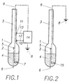
In der beigefügten Zeichnung sind die beiden beschriebenen Ausführungsbeispiele der Erfindung schematisch dargestellt, und zwar zeigt:
- Fig. 1
- ein Hypsometer mit einer auf der Basis einer Temperaturdifferenz-Messung durchgeführten Regelung der Heizleistung und
- Fig. 2
- ein Hypsometer mit einem NTC-Thermistor als Heizwiderstand.
- Fig. 1
- a hypsometer with a regulation of the heating power carried out on the basis of a temperature difference measurement and
- Fig. 2
- a hypsometer with an NTC thermistor as a heating resistor.
Das Hypsometer besteht in beiden Ausführungsformen aus einem Siedegefäss 1, z.B. aus Glas, das einen Gefässkolben 2 und einen an diesen anschliessenden, oben offenen Gefässhals 3 aufweist. Der Gefässkolben 2 enthält die Messflossigkeit 4, z.B. Wasser oder Methanol, und einen Temperaturfühler 5, vorzugsweise in Form eines elektrischen Thermoelementes, das die Siedepunkt-Temperatur im Dampfraum oberhalb des Flüssigkeitsspiegels misst und von dem eine Ableitung 6 nach aussen führt.In both embodiments, the hypsometer consists of a
Der Gefässkolben 2 enthält in der Ausführungsform nach Fig. 1 ferner einen in die Messflüssigkeit 4 eintauchenden elektrischen Heizwiderstand 7 üblicher Art, dem die Heizenergie aus einer Batterie 8 über eine Zuleitung 9 zugeführt wird. Unmittelbar oberhalb des Gefässkolbens 2 befinden sich zwei Messpunkte zur Bestimmung des Temperaturabfalls in dem durch diese Messpunkte begrenzten Bereich des Gefässhalses 3. An diesen Messpunkten ist je ein Temperaturfülhler 10 bzw. 11 angeordnet, der über eine Signalleitung 12 bzw. 13 mit einem Heizregler 14 verbunden ist. Dieser regelt die dem Heizwiderstand 7 zugeführte Heizleistung so, dass die Temperaturdifferenz zwischen den beiden Messpunkten auf einem bestimmten Sollwert von z.B. 1 °C gehalten wird.In the embodiment according to FIG. 1, the vessel piston 2 also contains an
Bei der Ausführungsform nach Fig. 2 ist anstelle eines gewöhnlichen Heizwiderstandes (7 in Fig. 1) ein Thermistor 15 mit negativem Temperaturkoeffizienten vorgesehen, der direkt aus der Batterie 8 über die Zuleitung 9 gespeist wird. Die in Fig. 1 vorhandene Regelschaltung mit den Teilen 10 bis 14 entfällt bei der Ausführung nach Fig. 2.In the embodiment according to FIG. 2, a
Claims (6)
- Hypsometer with controlled heating, in particular for use in meteorologic radio-sondes, with an open boiling vessel (1), which consists of a flask (2) containing the measuring liquid (4) and a neck (3) adjoining the flask, the vessel flask (2) comprising an electrical heating resistance (7) immersed in the measuring liquid (4) and a temperature sensor (5) monitoring the boiling point temperature, and an adaptive control system being provided, which controls the heating capacity at a value adapted to the respective boiling point temperature, characterised in that means (10, 11, Figure 1) are provided for measuring the temperature drop in the vessel neck (3) along a measuring section located at its lower end and that a certain temperature difference serves as a reference value for controlling the heating capacity, the control of the heating capacity being provided so that the position of the condensation zone is stabilised in the entire pressure range within the vessel neck (3).
- Hypsometer according to Claim 1, characterised in that the reference value of the temperature difference amounts to approximately 1°C.
- Hypsometer with controlled heating, in particular for use in meteorolgic radio-sondes, with an open boiling vessel (1), which consists of a flask (2) containing the measuring liquid (4) and a neck (3) adjoining the flask, the vessel flask (2) comprising an electrical heating resistance (7) immersed in the measuring liquid (4) and a temperature sensor (5) monitoring the boiling point temperature, and an adaptive control system being provided, which controls the heating capacity to a value adapted to the respective boiling point temperature, characterised in that provided as the heating resistance is a thermistor (15, Figure 2) operated at constant voltage, with a negative temperature coefficient, the control of the heating capacity being provided so that the position of the condensation zone is stabilised in the entire pressure range within the vessel neck (3).
- Hypsometer according to Claim 3, characterised in that the characteristic of the thermistor (15) and the heating capacity determined by its resistance value and the supply voltage are chosen so that there is supplied to the hypsometer in the entire pressure range, a heating capacity which is greater by a safety factor than would be necessary for boiling.
- Hypsometer according to Claim 1 or 3, characterised in that water serves as the measuring liquid (4).
- Hypsometer according to Claim 1 or 3, characterised in that methanol serves as the measuring liquid (4).
Applications Claiming Priority (2)
| Application Number | Priority Date | Filing Date | Title |
|---|---|---|---|
| DE3936839 | 1989-11-06 | ||
| DE3936839A DE3936839C1 (en) | 1989-11-06 | 1989-11-06 |
Publications (3)
| Publication Number | Publication Date |
|---|---|
| EP0427662A2 EP0427662A2 (en) | 1991-05-15 |
| EP0427662A3 EP0427662A3 (en) | 1991-09-11 |
| EP0427662B1 true EP0427662B1 (en) | 1994-07-13 |
Family
ID=6392925
Family Applications (1)
| Application Number | Title | Priority Date | Filing Date |
|---|---|---|---|
| EP90810399A Expired - Lifetime EP0427662B1 (en) | 1989-11-06 | 1990-05-30 | Hypsometer with controlled heating specially for use in meteorologic radio-sondes |
Country Status (7)
| Country | Link |
|---|---|
| US (1) | US5048337A (en) |
| EP (1) | EP0427662B1 (en) |
| JP (1) | JPH03167420A (en) |
| AT (1) | ATE108550T1 (en) |
| CA (1) | CA2018342C (en) |
| DE (2) | DE3936839C1 (en) |
| FI (1) | FI100738B (en) |
Families Citing this family (2)
| Publication number | Priority date | Publication date | Assignee | Title |
|---|---|---|---|---|
| US6530280B2 (en) * | 2001-03-26 | 2003-03-11 | George Schmermund | Hypsometer |
| CN108332898B (en) * | 2018-04-17 | 2023-05-09 | 南京信息工程大学 | Composite range air pressure sensor and high-precision air pressure detecting and measuring device |
Family Cites Families (4)
| Publication number | Priority date | Publication date | Assignee | Title |
|---|---|---|---|---|
| US2832219A (en) * | 1955-06-02 | 1958-04-29 | Victory Engineering Corp | Hypsometers |
| US2901909A (en) * | 1957-06-14 | 1959-09-01 | Photographic Survey Corp Ltd | Altitude sensing device |
| US3276262A (en) * | 1964-07-21 | 1966-10-04 | Victory Engineering Corp | Long operating hypsometer structure |
| US4388829A (en) * | 1981-10-05 | 1983-06-21 | Canadian Patents & Development Limited | Evaporation type barometer |
-
1989
- 1989-11-06 DE DE3936839A patent/DE3936839C1/de not_active Expired - Fee Related
-
1990
- 1990-05-30 AT AT90810399T patent/ATE108550T1/en not_active IP Right Cessation
- 1990-05-30 EP EP90810399A patent/EP0427662B1/en not_active Expired - Lifetime
- 1990-05-30 DE DE59006420T patent/DE59006420D1/en not_active Expired - Fee Related
- 1990-06-05 CA CA002018342A patent/CA2018342C/en not_active Expired - Fee Related
- 1990-06-07 US US07/534,427 patent/US5048337A/en not_active Expired - Fee Related
- 1990-06-28 JP JP2171314A patent/JPH03167420A/en active Pending
- 1990-07-18 FI FI903636A patent/FI100738B/en not_active IP Right Cessation
Also Published As
| Publication number | Publication date |
|---|---|
| EP0427662A3 (en) | 1991-09-11 |
| DE59006420D1 (en) | 1994-08-18 |
| FI903636A0 (en) | 1990-07-18 |
| US5048337A (en) | 1991-09-17 |
| CA2018342A1 (en) | 1991-05-06 |
| EP0427662A2 (en) | 1991-05-15 |
| FI100738B (en) | 1998-02-13 |
| JPH03167420A (en) | 1991-07-19 |
| CA2018342C (en) | 1996-10-29 |
| DE3936839C1 (en) | 1990-05-23 |
| ATE108550T1 (en) | 1994-07-15 |
Similar Documents
| Publication | Publication Date | Title |
|---|---|---|
| DE69723622T2 (en) | Infrared temperature detection for drum dryer control | |
| DE3818321C2 (en) | ||
| CH637203A5 (en) | VALVE FOR REFRIGERANT EVAPORATOR. | |
| DE2511592C2 (en) | Device for thermoanalytical investigations | |
| DE2813144C2 (en) | ||
| DE3413535C1 (en) | Measuring device for determining a proportion of liquid in the refrigerant | |
| DE102008051364A1 (en) | rotary evaporator | |
| DE3333907C2 (en) | ||
| DE3529956C2 (en) | ||
| DE3014955A1 (en) | TEMPERATURE STABILIZED CHAMBER, ESPECIALLY FOR A CRYSTAL OSCILLATOR | |
| EP0427662B1 (en) | Hypsometer with controlled heating specially for use in meteorologic radio-sondes | |
| DE2504659A1 (en) | PROCESS FOR COOLING A POLYMERIZATION REACTOR | |
| CH636430A5 (en) | VALVE FOR REFRIGERATION PLANTS. | |
| DE2138495A1 (en) | HEATING DEVICE FOR FLOW SENSORS | |
| DE19533510C2 (en) | Device for the removal and determination of dissolved components in liquids or gases | |
| DE1055018B (en) | Method for regulating a cooling machine and a cooling machine suitable for it | |
| EP0076951A1 (en) | Flow meter | |
| DE19957309C2 (en) | Computer-aided calibration method and device for carrying out the method | |
| DE2939355A1 (en) | Liq. level bridge circuit detector - has probe electrical heater subject to alternating heating and cooling periods, at different electric supply levels | |
| DE3942664A1 (en) | SENSOR ARRANGEMENT | |
| EP1199015A2 (en) | Pressure cooking vessel with a target boiling temperature which does not require calibration | |
| DE1501168A1 (en) | Control device for maintaining a constant cooling capacity of a coolant flow | |
| DE10114684C2 (en) | Process for generating moisture in an incubator | |
| DE3343072C2 (en) | ||
| EP0110872B1 (en) | Hypsometer |
Legal Events
| Date | Code | Title | Description |
|---|---|---|---|
| PUAI | Public reference made under article 153(3) epc to a published international application that has entered the european phase |
Free format text: ORIGINAL CODE: 0009012 |
|
| AK | Designated contracting states |
Kind code of ref document: A2 Designated state(s): AT BE CH DE DK ES FR GB GR IT LI LU NL SE |
|
| PUAL | Search report despatched |
Free format text: ORIGINAL CODE: 0009013 |
|
| AK | Designated contracting states |
Kind code of ref document: A3 Designated state(s): AT BE CH DE DK ES FR GB GR IT LI LU NL SE |
|
| 17P | Request for examination filed |
Effective date: 19911024 |
|
| 17Q | First examination report despatched |
Effective date: 19921222 |
|
| GRAA | (expected) grant |
Free format text: ORIGINAL CODE: 0009210 |
|
| AK | Designated contracting states |
Kind code of ref document: B1 Designated state(s): AT BE CH DE DK ES FR GB GR IT LI LU NL SE |
|
| PG25 | Lapsed in a contracting state [announced via postgrant information from national office to epo] |
Ref country code: IT Free format text: LAPSE BECAUSE OF FAILURE TO SUBMIT A TRANSLATION OF THE DESCRIPTION OR TO PAY THE FEE WITHIN THE PRE;WARNING: LAPSES OF ITALIAN PATENTS WITH EFFECTIVE DATE BEFORE 2007 MAY HAVE OCCURRED AT ANY TIME BEFORE 2007. THE CORRECT EFFECTIVE DATE MAY BE DIFFERENT FROM THE ONE RECORDED.SCRIBED TIME-LIMIT Effective date: 19940713 Ref country code: BE Effective date: 19940713 Ref country code: DK Effective date: 19940713 Ref country code: GR Free format text: LAPSE BECAUSE OF FAILURE TO SUBMIT A TRANSLATION OF THE DESCRIPTION OR TO PAY THE FEE WITHIN THE PRESCRIBED TIME-LIMIT Effective date: 19940713 Ref country code: ES Free format text: THE PATENT HAS BEEN ANNULLED BY A DECISION OF A NATIONAL AUTHORITY Effective date: 19940713 Ref country code: NL Effective date: 19940713 |
|
| REF | Corresponds to: |
Ref document number: 108550 Country of ref document: AT Date of ref document: 19940715 Kind code of ref document: T |
|
| GBT | Gb: translation of ep patent filed (gb section 77(6)(a)/1977) |
Effective date: 19940711 |
|
| REF | Corresponds to: |
Ref document number: 59006420 Country of ref document: DE Date of ref document: 19940818 |
|
| ET | Fr: translation filed | ||
| PG25 | Lapsed in a contracting state [announced via postgrant information from national office to epo] |
Ref country code: SE Effective date: 19941013 |
|
| NLV1 | Nl: lapsed or annulled due to failure to fulfill the requirements of art. 29p and 29m of the patents act | ||
| PLBE | No opposition filed within time limit |
Free format text: ORIGINAL CODE: 0009261 |
|
| STAA | Information on the status of an ep patent application or granted ep patent |
Free format text: STATUS: NO OPPOSITION FILED WITHIN TIME LIMIT |
|
| 26N | No opposition filed | ||
| PGFP | Annual fee paid to national office [announced via postgrant information from national office to epo] |
Ref country code: FR Payment date: 19980408 Year of fee payment: 9 |
|
| PGFP | Annual fee paid to national office [announced via postgrant information from national office to epo] |
Ref country code: AT Payment date: 19980415 Year of fee payment: 9 |
|
| PGFP | Annual fee paid to national office [announced via postgrant information from national office to epo] |
Ref country code: GB Payment date: 19980417 Year of fee payment: 9 |
|
| PGFP | Annual fee paid to national office [announced via postgrant information from national office to epo] |
Ref country code: CH Payment date: 19980428 Year of fee payment: 9 |
|
| PGFP | Annual fee paid to national office [announced via postgrant information from national office to epo] |
Ref country code: DE Payment date: 19980429 Year of fee payment: 9 Ref country code: LU Payment date: 19980429 Year of fee payment: 9 |
|
| PG25 | Lapsed in a contracting state [announced via postgrant information from national office to epo] |
Ref country code: GB Free format text: LAPSE BECAUSE OF NON-PAYMENT OF DUE FEES Effective date: 19990530 Ref country code: AT Free format text: LAPSE BECAUSE OF NON-PAYMENT OF DUE FEES Effective date: 19990530 Ref country code: LU Free format text: LAPSE BECAUSE OF NON-PAYMENT OF DUE FEES Effective date: 19990530 |
|
| PG25 | Lapsed in a contracting state [announced via postgrant information from national office to epo] |
Ref country code: CH Free format text: LAPSE BECAUSE OF NON-PAYMENT OF DUE FEES Effective date: 19990531 Ref country code: LI Free format text: LAPSE BECAUSE OF NON-PAYMENT OF DUE FEES Effective date: 19990531 |
|
| REG | Reference to a national code |
Ref country code: CH Ref legal event code: PL |
|
| GBPC | Gb: european patent ceased through non-payment of renewal fee |
Effective date: 19990530 |
|
| PG25 | Lapsed in a contracting state [announced via postgrant information from national office to epo] |
Ref country code: FR Free format text: LAPSE BECAUSE OF NON-PAYMENT OF DUE FEES Effective date: 20000131 |
|
| PG25 | Lapsed in a contracting state [announced via postgrant information from national office to epo] |
Ref country code: DE Free format text: LAPSE BECAUSE OF NON-PAYMENT OF DUE FEES Effective date: 20000301 |
|
| REG | Reference to a national code |
Ref country code: FR Ref legal event code: ST |