EP0427543B1 - Pneumatic tires - Google Patents
Pneumatic tires Download PDFInfo
- Publication number
- EP0427543B1 EP0427543B1 EP90312200A EP90312200A EP0427543B1 EP 0427543 B1 EP0427543 B1 EP 0427543B1 EP 90312200 A EP90312200 A EP 90312200A EP 90312200 A EP90312200 A EP 90312200A EP 0427543 B1 EP0427543 B1 EP 0427543B1
- Authority
- EP
- European Patent Office
- Prior art keywords
- tread
- pneumatic tire
- widthwise
- narrow
- circumferential groove
- Prior art date
- Legal status (The legal status is an assumption and is not a legal conclusion. Google has not performed a legal analysis and makes no representation as to the accuracy of the status listed.)
- Expired - Lifetime
Links
- 230000000694 effects Effects 0.000 description 6
- 238000005452 bending Methods 0.000 description 1
Images




Classifications
-
- B—PERFORMING OPERATIONS; TRANSPORTING
- B60—VEHICLES IN GENERAL
- B60C—VEHICLE TYRES; TYRE INFLATION; TYRE CHANGING; CONNECTING VALVES TO INFLATABLE ELASTIC BODIES IN GENERAL; DEVICES OR ARRANGEMENTS RELATED TO TYRES
- B60C11/00—Tyre tread bands; Tread patterns; Anti-skid inserts
- B60C11/01—Shape of the shoulders between tread and sidewall, e.g. rounded, stepped or cantilevered
-
- Y—GENERAL TAGGING OF NEW TECHNOLOGICAL DEVELOPMENTS; GENERAL TAGGING OF CROSS-SECTIONAL TECHNOLOGIES SPANNING OVER SEVERAL SECTIONS OF THE IPC; TECHNICAL SUBJECTS COVERED BY FORMER USPC CROSS-REFERENCE ART COLLECTIONS [XRACs] AND DIGESTS
- Y10—TECHNICAL SUBJECTS COVERED BY FORMER USPC
- Y10S—TECHNICAL SUBJECTS COVERED BY FORMER USPC CROSS-REFERENCE ART COLLECTIONS [XRACs] AND DIGESTS
- Y10S152/00—Resilient tires and wheels
- Y10S152/90—Tread pattern having no blocks and having circumferential ribs defined by zig-zag circumferential grooves
Definitions
- the present invention relates to pneumatic tires which can prevent uneven wearing at end portions of treads.
- each of shoulder ribs provided in the end portions of the tread is divided into two narrow ribs by forming a circumferential groove having given width, depth and interval in the shoulder rib.
- this pneumatic tire receives lateral forces, the ground contact pressure is made uniform through lateral deformation of the narrow ribs, so that occurrence of local wear acting as a core of uneven wear can be controlled.
- the laterally deformed amount of the narrow rib is substantially the same small value as that of the center rib when the tire receives the lateral forces. As a result, it cannot be said that the effect of controlling the occurrence of the above local wearing is sufficient.
- EP-A-0 285 695 discloses the features of the pre-characterizing part of claim 1 of the present application.
- the present invention aims to provide pneumatic tires in which uneven wearing at end portions of a tread can effectively be prevented.
- the present invention provides a pneumatic tire comprising a tread, wherein at least one circumferential groove having a width not greater than 0.1 times the width of the tread is formed in at least one end portion of the tread, thereby forming at least one narrow rib having a width not greater than 0.2 times that of the tread, characterized in that at least one of said at least one narrow rib projects radially outwardly from an extension line of a contour line of the tread by an amount of not more than 0.3 times of a gauge of the tread.
- uneven wearing at the end portion of the tread such as edge-drop wearing, wavy wearing, shoulder-drop wearing or polygonal wearing occurs, starting from occurrence of local wearing due to rapid increase in the share of the lateral forces by the end portion of the tread upon receipt of lateral forces during cornering or the like, followed by spreading of such local wearing in every direction.
- At least one circumferential groove is provided in the end portion of the tread so that at least one narrow rib having a given width is formed.
- the laterally deformed amount of the narrow rib becomes greater than the deformed amount of the land portion located near the narrow rib. Consequently, the occurrence of the local wearing of the land portion located widthwise inside the narrow rib can be prevented. Accordingly, since the occurrence of the local wearing is prevented as mentioned above, the local wearing can be effectively prevented from occurring at the end portion of the tread.
- a reference numeral 1 denotes a pneumatic radial tire in which a plurality (three in this embodiment) of zigzag main grooves 3 circumferentially extend in a surface of a tread 2 of the tire 1.
- Each of the main grooves 3 has such a width that groove walls thereof may not contact each other even at a ground contact zone during rotation of the tire 1 under load.
- two circumferentially extending center ribs 6a and 6b are formed in the tread 2 between these main grooves 3, while two shoulder ribs 7a and 7b are formed between the axially outermost main grooves 3 and the ends 4 and 5 of the tread.
- At least one (two in this embodiment) straight extending, circumferential grooves 11, 12, 13 and 14 are formed in each of widthwise opposite end portions of the tread 2, i.e., in each of widthwise outer portions of the shoulder ribs 7a and 7b in this embodiment.
- narrow ribs 15 and 16 are defined between the circumferential groove 11 and the end 4 of the tread and between the circumferential groove 14 and the end 5 of the tread, respectively.
- narrow ribs 17 and 18 are defined between the circumferential grooves 11 and 12 and between the circumferential grooves 13 and 14, respectively.
- remaining ribs 19 and 20 are defined as land portions between the circumferential groove 12 and the adjacent main groove 3 and between the circumferential groove 13 and the adjacent main groove 3, respectively.
- the circumferential grooves 11, 12, 13 and 14 need only to extend generally in the substantially circumferential direction, not in a strictly circumferential direction.
- the width A of each of the circumferential grooves 11, 12, 13 and 14 is not more than 0.1 times the width W of the tread. The reason is that if the former exceeds 0.1 times the latter, the narrow ribs 15 and 17 and the narrow ribs 16 and 18 are spaced too much from the widthwise outermost portions P of the remaining ribs 19 and 20, respectively. Consequently, the narrow ribs 15, 16, 17 and 18 do not influence the remaining ribs 19 and 20 as mentioned later, so that the uneven wearing-preventing effect cannot be expected. Further, the width B of each of the narrow ribs 15, 16, 17 and 18 is not more than 0.2 times the width W of the tread.
- the width B of each of the narrow ribs 15, 16, 17 and 18 is in a range of 0.01 times to 0.1 times the width W of the tread. The reason is that if the former is less than 0.01 times, the ground contact pressure cannot be made sufficiently uniform due to low lateral rigidity of the narrow ribs 15, 16, 17 and 18, even when the narrow ribs 15, 16, 17 and 18 are laterally deformed.
- the width B is more 0.1 times the width W, the rigidity of the narrow ribs 15, 16, 17 and 18 increases to some extent, so that the laterally deformed amount thereof upon receipt of the lateral forces are suppressed, and it cannot be said that the uneven wearing-preventing effect is sufficient. If such a tire is subjected to cornering, it is considered that the share of the lateral forces by the widthwise end portion of the tread 2 rapidly increases upon receipt of the lateral forces so that local wearing occurs as a core of uneven wearing.
- the narrow ribs 15, 16, 17 and 18 having the specified width B are defined by forming the circumferential grooves 11, 12, 13 and 14 having the specified width A in the widthwise end portions of the tread 2 as mentioned above, the narrow ribs 15, 16, 17 and 18 having the low rigidity are laterally deformed in the acting direction of the lateral forces (widthwise inward direction) upon receipt of the lateral forces as mentioned above.
- the land portions near the narrow ribs 15 and 17 and the narrow ribs 16 and 18, i.e. the widthwise outer end portions of the remaining ribs 19 and 20 in this embodiment are influenced by lateral deformation of the narrow ribs 15, 16, 17 and 18, so that the ground contact pressure distribution is made uniform.
- At least one narrow rib (only the widthwise innermost narrow ribs 17 and 18 in this embodiment) among the narrow ribs 15, 16, 17 and 18 is projected radially outwardly from the extension line of the contour line L of the tread.
- the contour line L of the tread is an arc of the contour of the tread 2 in a radial section.
- the radially outwardly projecting amount J of the narrow rib 17, 18 is not more than 0.3 times as much as the gauge H of the tread.
- the reason is that if the projecting amount J is more than 0.3 times the gauge H of the tread, the radially outwardly projecting end portions of the narrow ribs 17 and 18 are easily cut during running of the tire 1.
- the gauge H of the tread means the radial distance from a radially outer surface of the belt layer V or an extension surface of this radially outer surface to the outer surface of the tread 2.
- the projecting amount J is preferably not less than 0.02 times as much as the gauge H of the tread. The reason is that if it is less than 0.02 times, the uneven wear-preventing effect mentioned later is insufficient.
- the laterally deformed amount of the narrow rib 17, 18 is greater than that of the land portion positioned adjacent the narrow rib 17, 18, i.e. the remaining ribs 19, 20 when the tire receives lateral forces, and occurrence of uneven wear at the widthwise outer end portions P of the land portions located widthwise inside the narrow ribs 17 and 18, i.e. the remaining ribs 19 and 20 in this embodiment, can assuredly be prevented.
- the widthwise innermost narrow ribs 17 and 18, which are nearest the land portions (the remaining ribs 19 and 20 in this embodiment) among the narrow ribs 15, 16, 17 and 18 and can thus greatly influence the land portions, project outwardly occurrence of the local wear at the widthwise outer end portions P of the remaining ribs 19 and 20 positioned widthwise inside the narrow ribs 17 and 18, respectively, can more assuredly be prevented.
- uneven wear such as edge drop wear, wavy wear, shoulder drop wear, and polygonal wear at the widthwise opposite portions of the tread 2 can effectively be prevented.
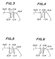
- Fig. 3 is a partially sectional view illustrating the second embodiment of the present invention.
- an inclined portion 25 is provided at a widthwise outer end portion P of a remaining rib 19, 20 such that the inclined portion is disposed radially inwardly in a widthwise outer direction of the tire.
- Fig. 4 is a partially sectional view illustrating the third embodiment of the present invention.
- the widthwise innermost narrow ribs 17 and 18 but also the narrow ribs 15 and 16 positioned widthwise outside the narrow ribs 17 and 18 are radially outwardly projected by the same amount. By so doing, the effect of preventing the uneven wear is enhanced.
- Fig. 5 is a partially sectional view of illustrating the fourth embodiment of the present invention.
- the widthwise inner wall of the circumferential groove 12, 13 is inclined to approach the end 4, 5 of the tread in the radially outer direction of the tire, the ground contact pressure at the widthwise outer end portion P of the remaining rib 19, 20 is reduced, so that the occurrence of the local wear can more assuredly be prevented.
- Fig. 6 is a partially sectional view of the fifth embodiment of the present invention.
- circumferential grooves 11, 12, 13, 14 and narrow ribs 17 and 18 are inclined to approach the tread ends 4, 5 in the radially outer direction.
- Fig. 7 is a partially sectional view of the sixth embodiment of the present invention.
- the width A3 of the circumferential groove 12, 13 is made narrower than the width A4 of the circumferential groove 11, 14.
- Fig. 8 is a partially sectional view of the seventh embodiment of the present invention.
- the width A of each of the circumferential grooves 11, 12, 13 and 14 is made narrower.
- Fig. 9 is a partially sectional view of the eighth embodiment of the present invention.
- the width of the axially outer circumferential groove 11, 14 is made narrower, and a ring-like space 30 is formed axially inside the circumferential groove and connected to a bottom portion of the circumferential groove 12, 13.
- Fig. 10 is a partially sectional view of the ninth embodiment of the present invention.
- the narrow ribs 15 and 16 positioned on widthwise outer sides of the tread are projected radially outwardly from an extension line of the contour line L of the tread.
- the occurrence of the local wear at the widthwise outer end portions P of the remaining ribs 19 and 20 can also assuredly be prevented.
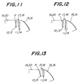
- Fig. 11 is a partially sectional view of the tenth embodiment of the present invention.
- the widthwise outermost circumferential grooves 11 and 14 are deeper than the widthwise outermost but one circumferential grooves 12 and 13, respectively.
- Fig. 12 is a partially sectional view of the eleventh embodiment of the present invention.
- the widthwise outermost circumferential grooves 11 and 14 are deeper than the widthwise outermost but one circumferential grooves 12 and 13, respectively.
- the bottom portions of the widthwise outermost circumferential grooves 11 and 14 are enlarged as shown.
- Fig. 13 is a partially sectional view of the twelfth embodiment of the present invention.
- the width of the widthwise outermost but one circumferential groove 12, 13 becomes gradually smaller in the radially inner directions.
- Fig. 14 is a partially sectional view of the thirteenth embodiment of the present invention.
- a single circumferential groove 31 is formed in each of widthwise opposite end portions of the tread 2 to define a single narrow rib 32 between the circumferential groove 31 and the tread end 4, 5, and the narrow rib 32 is projected radially outwardly from the contour line L of the tread.
- Fig. 15 is a partially sectional view of the fourteenth embodiment of the present invention.
- the radially outer end of the narrow rib 17, 18 is made in flush with the extension line of the contour line L of the tread, and the circumferential grooves 11, 12, 13 and 14 and the narrow ribs 17 and 18 are inclined to approach the ends 4, 5 of the tread in the radially outer direction, so that when the narrow rib 17, 18 is laterally deformed upon receipt of lateral forces, the radially outer end of the narrow rib 17, 18 is projected radially outwardly from the extension line of the contour line L of the tread as shown by an imaginary line.
- the tire can easily be molded, and a use amount of rubber can be reduced.
- Fig. 16 is a partially plan view of the fifteenth embodiment of the present invention.
- the circumferential grooves 11, 12, 13 and 14 and the narrow ribs 17 and 18 are zigzag in shape. Therefore, the phenomenon that the surface of the tread is radially outwardly swelled can be controlled.
- Fig. 17 is a partially plan view of the sixteenth embodiment of the present invention.
- the narrow ribs 15, 16, 17 and 18 and the remaining ribs 19 and 20 are divided into blocks by a plurality of lateral grooves 35 axially extending and spaced in the circumferential direction by an equal distance, respectively.
- Fig. 18 is a partially plan view illustrating the seventeenth embodiment.
- the narrow ribs 15, 16, 17 and 18 as well as the remaining ribs 19 and 20 are divided into blocks by a plurality of lateral grooves 36 circumferentially spaced by an equal distance and inclined with respect to the axis of the tire, and the circumferential grooves 11, 12, 13 and 14 and the narrow ribs 17 and 18 are inclined by a given angle with respect to the circumferential direction.
- the circumferential grooves 11, 12, 13 and 14 and the narrow ribs 15, 16, 17 and 18 are formed in the widthwise opposed end portions of the tread 2.
- the circumferential grooves and the narrow grooves may be formed in the end portion of the tread on one side.
- the tire has only to be fitted to a vehicle such that the side of the tire on which the circumferential grooves and the narrow ribs are formed may be located on a side in which uneven wearing is likely to occur.
- one or two of the circumferential grooves are provided, and one or two narrow ribs are defined therebetween.
- three or more circumferential grooves and three or more narrow ribs may be formed in each of or one of the widthwise opposed sides of the tread.
Landscapes
- Engineering & Computer Science (AREA)
- Mechanical Engineering (AREA)
- Tires In General (AREA)
Description
- The present invention relates to pneumatic tires which can prevent uneven wearing at end portions of treads.
- As far as pneumatic radial tires capable of preventing uneven wearing at the end portions of the treads are concerned, tires described in Japanese Patent application Laid-open No. 61-143,205 (corresponding to GB-A-2 170 153) are known. In the tires of this type, each of shoulder ribs provided in the end portions of the tread is divided into two narrow ribs by forming a circumferential groove having given width, depth and interval in the shoulder rib. When this pneumatic tire receives lateral forces, the ground contact pressure is made uniform through lateral deformation of the narrow ribs, so that occurrence of local wear acting as a core of uneven wear can be controlled.
- However, in the case of such a tire, since the radially outer portion of the narrow rib is at the same level as the contour line of the tread, that is since the radially outer portion of the other shoulder ribs not divided is at the same level as that of the center rib, the laterally deformed amount of the narrow rib is substantially the same small value as that of the center rib when the tire receives the lateral forces. As a result, it cannot be said that the effect of controlling the occurrence of the above local wearing is sufficient.
- Attention is drawn to EP-A-0 285 695, which discloses the features of the pre-characterizing part of claim 1 of the present application.
- The present invention aims to provide pneumatic tires in which uneven wearing at end portions of a tread can effectively be prevented.
- The present invention provides a pneumatic tire comprising a tread, wherein at least one circumferential groove having a width not greater than 0.1 times the width of the tread is formed in at least one end portion of the tread, thereby forming at least one narrow rib having a width not greater than 0.2 times that of the tread, characterized in that at least one of said at least one narrow rib projects radially outwardly from an extension line of a contour line of the tread by an amount of not more than 0.3 times of a gauge of the tread.
- In general, uneven wearing at the end portion of the tread, such as edge-drop wearing, wavy wearing, shoulder-drop wearing or polygonal wearing occurs, starting from occurrence of local wearing due to rapid increase in the share of the lateral forces by the end portion of the tread upon receipt of lateral forces during cornering or the like, followed by spreading of such local wearing in every direction.
- For this reason, in the present invention, at least one circumferential groove is provided in the end portion of the tread so that at least one narrow rib having a given width is formed. As a result, when the tire receives lateral forces during cornering or the like, the narrow rib having low rigidity is laterally deformed in an acting direction of the lateral forces (in the widthwise inward direction of the tire) to make the ground contact pressure uniform near the narrow rib. Thereby, occurrence of local wearing at a land portion located widthwise inside the narrow rib is prevented. At this time, since at least one of said at least one narrow rib is projected radially outwardly from the extension line of the contour line of the tread in the present invention, the laterally deformed amount of the narrow rib becomes greater than the deformed amount of the land portion located near the narrow rib. Consequently, the occurrence of the local wearing of the land portion located widthwise inside the narrow rib can be prevented. Accordingly, since the occurrence of the local wearing is prevented as mentioned above, the local wearing can be effectively prevented from occurring at the end portion of the tread.
- The invention will be further described with reference is made to the accompanying drawings, wherein:
- Fig. 1 is a developed view of a tread as a first embodiment of the present invention;
- Fig. 2 is a sectional view of Fig. 1 as viewed in the direction of the arrows II-II;
- Fig. 3 is a partially sectional view of a second embodiment of the present invention along a meridian line;
- Fig. 4 is a partially sectional view of a third embodiment of the present invention along a meridian line;
- Fig. 5 is a partially sectional view of a fourth embodiment of the present invention along a meridian line;
- Fig. 6 is a partially sectional view of a fifth embodiment of the present invention along a meridian line;
- Fig. 7 is a partially sectional view of a sixth embodiment of the present invention along a meridian line;
- Fig. 8 is a partially sectional view of a seventh embodiment of the present invention along a meridian line;
- Fig. 9 is a partially sectional view of an eighth embodiment of the present invention along a meridian line;
- Fig. 10 is a partially sectional view of a ninth embodiment of the present invention along a meridian line;
- Fig. 11 is a partially sectional view of a tenth embodiment of the present invention along a meridian line;
- Fig. 12 is a partially sectional view of an eleventh embodiment of the present invention along a meridian line;
- Fig. 13 is a partially sectional view of a twelfth embodiment of the present invention along a meridian line;
- Fig. 14 is a partially sectional view of a thirteenth embodiment of the present invention along a meridian line;
- Fig. 15 is a partially sectional view of a fourteenth embodiment of the present invention along a meridian line;
- Fig. 16 is a partially plan view of a tread pattern of a fifteen embodiment of the present invention;
- Fig. 17 is a partially plan view of a tread pattern of a sixteenth embodiment of the present invention; and
- Fig. 18 is a partially plan view of a tread pattern of a seventeenth embodiment of the present invention.
- The first embodiment of the present invention will be explained with reference to the drawings.
- In Figs. 1 and 2, a reference numeral 1 denotes a pneumatic radial tire in which a plurality (three in this embodiment) of zigzag
main grooves 3 circumferentially extend in a surface of atread 2 of the tire 1. Each of themain grooves 3 has such a width that groove walls thereof may not contact each other even at a ground contact zone during rotation of the tire 1 under load. When a plurality of themain grooves 3 are formed in thetread 2 as mentioned above, two circumferentially extendingcenter ribs tread 2 between thesemain grooves 3, while twoshoulder ribs main grooves 3 and theends circumferential grooves tread 2, i.e., in each of widthwise outer portions of theshoulder ribs narrow ribs circumferential groove 11 and theend 4 of the tread and between thecircumferential groove 14 and theend 5 of the tread, respectively. On the other hand,narrow ribs circumferential grooves circumferential grooves remaining ribs circumferential groove 12 and the adjacentmain groove 3 and between thecircumferential groove 13 and the adjacentmain groove 3, respectively. Thecircumferential grooves - The width A of each of the
circumferential grooves narrow ribs narrow ribs remaining ribs narrow ribs remaining ribs narrow ribs narrow ribs narrow rib narrow ribs narrow ribs narrow ribs narrow ribs tread 2 rapidly increases upon receipt of the lateral forces so that local wearing occurs as a core of uneven wearing. However, in this embodiment, since thenarrow ribs circumferential grooves tread 2 as mentioned above, thenarrow ribs narrow ribs narrow ribs remaining ribs narrow ribs remaining ribs narrow ribs narrow ribs tread 2 in a radial section. The radially outwardly projecting amount J of thenarrow rib narrow ribs tread 2. The projecting amount J is preferably not less than 0.02 times as much as the gauge H of the tread. The reason is that if it is less than 0.02 times, the uneven wear-preventing effect mentioned later is insufficient. Since thenarrow ribs narrow rib narrow rib remaining ribs narrow ribs remaining ribs narrow ribs ribs narrow ribs ribs narrow ribs tread 2 can effectively be prevented. - Fig. 3 is a partially sectional view illustrating the second embodiment of the present invention. In this embodiment, an inclined portion 25 is provided at a widthwise outer end portion P of a remaining
rib rib - Fig. 4 is a partially sectional view illustrating the third embodiment of the present invention. In this embodiment, not only the widthwise innermost
narrow ribs narrow ribs narrow ribs - Fig. 5 is a partially sectional view of illustrating the fourth embodiment of the present invention. In this embodiment, since the widthwise inner wall of the
circumferential groove end rib - Fig. 6 is a partially sectional view of the fifth embodiment of the present invention. In this embodiment,
circumferential grooves narrow ribs - Fig. 7 is a partially sectional view of the sixth embodiment of the present invention. In this embodiment, the width A3 of the
circumferential groove circumferential groove rib - Fig. 8 is a partially sectional view of the seventh embodiment of the present invention. In this embodiment, the width A of each of the
circumferential grooves tread 2 can prevented. - Fig. 9 is a partially sectional view of the eighth embodiment of the present invention. In this embodiment, the width of the axially outer
circumferential groove circumferential groove tread 2 can be prevented more assuredly. - Fig. 10 is a partially sectional view of the ninth embodiment of the present invention. In this embodiment, the
narrow ribs ribs - Fig. 11 is a partially sectional view of the tenth embodiment of the present invention. In this embodiment, the widthwise outermost
circumferential grooves circumferential grooves - Fig. 12 is a partially sectional view of the eleventh embodiment of the present invention. In this embodiment, the widthwise outermost
circumferential grooves circumferential grooves circumferential grooves - Fig. 13 is a partially sectional view of the twelfth embodiment of the present invention. In this embodiment, the width of the widthwise outermost but one
circumferential groove - Fig. 14 is a partially sectional view of the thirteenth embodiment of the present invention. In this embodiment, a single
circumferential groove 31 is formed in each of widthwise opposite end portions of thetread 2 to define a singlenarrow rib 32 between thecircumferential groove 31 and thetread end narrow rib 32 is projected radially outwardly from the contour line L of the tread. By so doing, the occurrence of uneven wear can be prevented by such a simple structure. - Fig. 15 is a partially sectional view of the fourteenth embodiment of the present invention. In this embodiment, under application of no load, the radially outer end of the
narrow rib circumferential grooves narrow ribs ends narrow rib narrow rib - Fig. 16 is a partially plan view of the fifteenth embodiment of the present invention. In this embodiment, the
circumferential grooves narrow ribs - Fig. 17 is a partially plan view of the sixteenth embodiment of the present invention. In this embodiment, the
narrow ribs ribs lateral grooves 35 axially extending and spaced in the circumferential direction by an equal distance, respectively. By so doing, that share of load which is borne by a kicking-out portions of these blocks is reduced to suppress heel-and-toe wear. - Fig. 18 is a partially plan view illustrating the seventeenth embodiment. In this embodiment, the
narrow ribs ribs lateral grooves 36 circumferentially spaced by an equal distance and inclined with respect to the axis of the tire, and thecircumferential grooves narrow ribs - In the above-mentioned embodiments, the
circumferential grooves narrow ribs tread 2. However, in the present invention, the circumferential grooves and the narrow grooves may be formed in the end portion of the tread on one side. In such a case, the tire has only to be fitted to a vehicle such that the side of the tire on which the circumferential grooves and the narrow ribs are formed may be located on a side in which uneven wearing is likely to occur. Further, in the above-mentioned embodiments, with respect to each of the widthwise opposed sides of thetread 2, one or two of the circumferential grooves are provided, and one or two narrow ribs are defined therebetween. However, according to the present invention, three or more circumferential grooves and three or more narrow ribs may be formed in each of or one of the widthwise opposed sides of the tread. - As mentioned above, according to the present invention, local wearing as a core of uneven wear can assuredly be prevented, so that uneven wearing at the end portions of the tread can effectively be prevented.
Claims (19)
- A pneumatic tire (1) comprising a tread (2), wherein at least one circumferential groove (11,12,13,14) having a width (A) not greater than 0.1 times the width (W) of the tread is formed in at least one end portion of the tread, thereby forming at least one narrow rib (15,16,17,18) having a width (B) not greater than 0.2 times that of the tread, characterized in that at least one (17,18) of said at least one narrow rib projects radially outwardly from an extension line of a contour line (L) of the tread by an amount (J) of not more than 0.3 times of a gauge (H) of the tread.
- A pneumatic tire as claimed in claim 1, characterized in that the width (B) of the narrow rib is in a range of 0.01 times to 0.1 times the width (W) of the tread.
- A pneumatic tire as claimed in claim 1 or 2, characterized in that said radially projecting amount (J) is not less than 0.02 times the gauge (H) of the tread.
- A pneumatic tire as claimed in any of claims 1 to 3, characterized in that an inclined portion (25) is provided at a widthwise outer end portion (P) of a remaining rib (19,20) such that the inclined portion is disposed radially inwardly in a widthwise outer direction of the tire.
- A pneumatic tire as claimed in any of claims 1 to 3, characterized in that not only widthwise innermost narrow ribs (17,18) but also narrow ribs (15,16) positioned widthwise outside the narrow ribs (17,18) are radially outwardly projected by the same amount.
- A pneumatic tire as claimed in any of claims 1 to 3, characterized in that a widthwise inner wall of the circumferential groove (12,13) is inclined to approach an adjacent end (4,5) of the tread in the radially outer direction of the tire.
- A pneumatic tire as claimed in any of claims 1 to 3, characterized in that the circumferential groove (11,12,13,14) and the narrow rib (17,18) are inclined to approach the tread ends (4,5) in the radially outer direction.
- A pneumatic tire as claimed in any of claims 1 to 3, characterized in that the width (A3) of the axially inner circumferential groove (12,13) is made narrower than the width (A4) of the axially outer circumferential groove (11,14).
- A pneumatic tire as claimed in any of claims 1 to 3, characterized in that the width (A) of the axially outer circumferential groove is made narrower.
- A pneumatic tire as claimed in any of claims 1 to 3, characterized in that the width of the axially outer circumferential groove (11,14) is made narrower and a ring-like space (30) is formed axially inside the circumferential groove and connected to a bottom portion of the circumferential groove.
- A pneumatic tire as claimed in any of claims 1 to 3, characterized in that the narrow rib (15,16) positioned on the widthwise outer side of the tread is projected radially outwardly from the extension line of the contour line of the tread.
- A pneumatic tire as claimed in any of claims 1 to 3, characterized in that the widthwise outermost grooves (11,14) are deeper than the widthwise outermost but one grooves (12,13), respectively.
- A pneumatic tire as claimed in any of claims 1 to 3, characterized in that the widthwise outermost grooves (11,14) are deeper than the widthwise outermost but one grooves (12,13), respectively, and the bottom portions of the widthwise outermost grooves (11,14) are enlarged.
- A pneumatic tire as claimed in any of claims 1 to 3, characterized in that the width of the widthwise outermost but one groove (12,13) becomes gradually smaller in a radially inner direction.
- A pneumatic tire as claimed in any of claims 1 to 3, characterized in that a single circumferential groove (31) is formed in each of widthwise opposite end portions of the tread to define a single narrow rib (32) between the circumferential groove (31) and the tread end (4,5), and the narrow rib (32) is projected radially outwardly from the contour line (L) of the tread.
- A pneumatic tire as claimed in any of claims 1 to 3, characterized in that, under application of no load, the radially outer end of the narrow rib (17,18) is made flush with the extension line of the contour line (L) of the tread, and the circumferential groove (11,12,13,14) and the narrow rib (17,18) are inclined to approach an adjacent end (4,5) of the tread in the radially outer direction, so that when the narrow rib (17,18) is laterally deformed upon receipt of lateral force, the radially outer end of the narrow rib projects radially outwardly from the extension line of the contour line (L) of the tread.
- A pneumatic tire as claimed in any of claims 1 to 16, characterized in that the circumferential groove (11,12,13,14) and the narrow rib (17,18) are zigzag in shape.
- A pneumatic tire as claimed in any of claims 1 to 16, characterized in that the narrow rib (15,16,17,18) and the remaining rib (19,20) are divided into blocks by a plurality of lateral grooves (35) axially extending and spaced in the circumferential direction by an equal distance, respectively.
- A pneumatic tire as claimed in any of claims 1 to 16, characterized in that the narrow rib (15,16,17,18) as well as the remaining rib (19,20) are divided into blocks by a plurality of lateral grooves (36) circumferentially spaced by an equal distance and inclined with respect to the axis of the tire, and the circumferential groove (11,12,13,14) and the narrow rib (17,18) are inclined by a given angle with respect to the circumferential direction.
Applications Claiming Priority (2)
| Application Number | Priority Date | Filing Date | Title |
|---|---|---|---|
| JP293429/89 | 1989-11-10 | ||
| JP1293429A JPH068081B2 (en) | 1989-11-10 | 1989-11-10 | Pneumatic tire |
Publications (3)
| Publication Number | Publication Date |
|---|---|
| EP0427543A2 EP0427543A2 (en) | 1991-05-15 |
| EP0427543A3 EP0427543A3 (en) | 1991-09-11 |
| EP0427543B1 true EP0427543B1 (en) | 1995-03-22 |
Family
ID=17794644
Family Applications (1)
| Application Number | Title | Priority Date | Filing Date |
|---|---|---|---|
| EP90312200A Expired - Lifetime EP0427543B1 (en) | 1989-11-10 | 1990-11-08 | Pneumatic tires |
Country Status (4)
| Country | Link |
|---|---|
| US (1) | US5323825A (en) |
| EP (1) | EP0427543B1 (en) |
| JP (1) | JPH068081B2 (en) |
| DE (1) | DE69018013T2 (en) |
Families Citing this family (19)
| Publication number | Priority date | Publication date | Assignee | Title |
|---|---|---|---|---|
| FI115039B (en) * | 1993-06-14 | 2005-02-28 | Sumitomo Rubber Ind | Nabbless tire |
| JP3344794B2 (en) * | 1993-12-15 | 2002-11-18 | 横浜ゴム株式会社 | Pneumatic radial tire |
| JP2786398B2 (en) * | 1993-12-27 | 1998-08-13 | 住友ゴム工業株式会社 | Heavy duty pneumatic tires |
| US5833780A (en) * | 1995-06-21 | 1998-11-10 | The Yokohama Rubber Co., Ltd. | Pneumatic radial tire for heavy loads |
| JP3717617B2 (en) * | 1996-02-02 | 2005-11-16 | 株式会社ブリヂストン | Pneumatic radial tire |
| EP0816131B1 (en) * | 1996-07-04 | 2000-11-08 | Sumitomo Rubber Industries Limited | Heavy duty pneumatic tyre |
| JP3515296B2 (en) * | 1996-10-28 | 2004-04-05 | 横浜ゴム株式会社 | Heavy duty pneumatic tires |
| CN1133548C (en) | 1996-12-19 | 2004-01-07 | 米凯林技术研究公司 | Sacrificial ribs for improved tire wear |
| BR0100126A (en) * | 2000-02-01 | 2001-08-28 | Goodyear Tire & Rubber | Radial tire with improved canvas line |
| JP2002002223A (en) * | 2000-06-21 | 2002-01-08 | Yokohama Rubber Co Ltd:The | Pneumatic tire |
| USD451438S1 (en) | 2000-08-31 | 2001-12-04 | The Goodyear Tire & Rubber Company | Tire tread |
| US7090735B2 (en) | 2001-08-06 | 2006-08-15 | Bridgestone/Firestone North American Tire, Llc | Method of compensating for residual aligning torque (RAT) |
| US20040060628A1 (en) * | 2002-09-30 | 2004-04-01 | Grimm John H.W. | Heavy duty pneumatic tire |
| JP4813230B2 (en) * | 2006-03-29 | 2011-11-09 | 東洋ゴム工業株式会社 | Pneumatic tire |
| US20070267115A1 (en) * | 2006-05-18 | 2007-11-22 | Continental Tire North America, Inc. | Pneumatic tire with decoupling groove |
| CN101631684B (en) * | 2007-03-13 | 2011-06-22 | 株式会社普利司通 | pneumatic tire |
| CN102481810B (en) * | 2009-07-27 | 2015-04-08 | 株式会社普利司通 | Tire for construction vehicle |
| DE112012006301B9 (en) * | 2012-07-13 | 2019-11-28 | The Yokohama Rubber Co., Ltd. | tire |
| JP6599218B2 (en) * | 2015-11-18 | 2019-10-30 | Toyo Tire株式会社 | Pneumatic tire |
Family Cites Families (16)
| Publication number | Priority date | Publication date | Assignee | Title |
|---|---|---|---|---|
| NL243647A (en) * | 1958-09-23 | |||
| NL135847C (en) * | 1968-03-18 | |||
| JPS533124B2 (en) * | 1974-10-23 | 1978-02-03 | ||
| JPS54159902A (en) * | 1978-06-07 | 1979-12-18 | Toyo Tire & Rubber Co Ltd | Radial tire |
| US4480671A (en) * | 1982-04-26 | 1984-11-06 | Michelin Recherche Et Technique S.A. | Tread and heavy duty tire |
| JPS6022505A (en) * | 1983-07-19 | 1985-02-05 | Bridgestone Corp | Pneumatic belted tire for motorcycle |
| JPS6033105A (en) * | 1983-08-01 | 1985-02-20 | Sumitomo Rubber Ind Ltd | Tire for motorcycle |
| JPS6064003A (en) * | 1983-09-20 | 1985-04-12 | Sumitomo Rubber Ind Ltd | Tire for motor truck and bus |
| JPS60244605A (en) * | 1984-05-17 | 1985-12-04 | Sumitomo Rubber Ind Ltd | Motorcycle tire |
| JPH064364B2 (en) * | 1984-12-14 | 1994-01-19 | 株式会社ブリヂストン | Pneumatic radial tires for trucks and buses |
| JPS62295702A (en) * | 1986-06-14 | 1987-12-23 | Sumitomo Rubber Ind Ltd | Steel radial tire improved in eccentric abrasion characteristic |
| JPS6332002U (en) * | 1986-08-19 | 1988-03-01 | ||
| JPS63134313A (en) * | 1986-11-25 | 1988-06-06 | Yokohama Rubber Co Ltd:The | Pnermatic radial tire |
| JP2617713B2 (en) * | 1987-03-26 | 1997-06-04 | 横浜ゴム株式会社 | Pneumatic radial tire for heavy loads |
| JPH0195911A (en) * | 1987-10-07 | 1989-04-14 | Toyo Tire & Rubber Co Ltd | Tread pattern for pneumatic tire prevented from uneven wear |
| JPH01215605A (en) * | 1988-02-23 | 1989-08-29 | Toyo Tire & Rubber Co Ltd | Tread pattern of pneumatic tire with reduced deflective abrasion |
-
1989
- 1989-11-10 JP JP1293429A patent/JPH068081B2/en not_active Expired - Fee Related
-
1990
- 1990-11-08 EP EP90312200A patent/EP0427543B1/en not_active Expired - Lifetime
- 1990-11-08 DE DE69018013T patent/DE69018013T2/en not_active Expired - Fee Related
-
1992
- 1992-07-06 US US07/908,647 patent/US5323825A/en not_active Expired - Lifetime
Also Published As
| Publication number | Publication date |
|---|---|
| EP0427543A2 (en) | 1991-05-15 |
| DE69018013D1 (en) | 1995-04-27 |
| EP0427543A3 (en) | 1991-09-11 |
| JPH03153403A (en) | 1991-07-01 |
| JPH068081B2 (en) | 1994-02-02 |
| US5323825A (en) | 1994-06-28 |
| DE69018013T2 (en) | 1995-10-12 |
Similar Documents
| Publication | Publication Date | Title |
|---|---|---|
| US6116309A (en) | Tread for a tire including five rib parts | |
| US5323825A (en) | Pneumatic tires | |
| US5131444A (en) | Heavy duty pneumatic tires including stepped tread zones for preventing uneven wearing | |
| EP0598300B1 (en) | A tread for a tire | |
| EP0422902B1 (en) | Pneumatic radial tires | |
| US5665184A (en) | Heavy duty pneumatic tire | |
| US6142200A (en) | Truck steer tire tread including circumferential grooves | |
| US5099899A (en) | Pneumatic radial tire for heavy load vehicles having increasing circumferential groove amplitude with wear | |
| EP1510368B1 (en) | Pneumatic tire having excellent steering stability | |
| JP3533757B2 (en) | Pneumatic tire | |
| EP0904960B1 (en) | Studless tyre | |
| US4977942A (en) | Pneumatic tire having defined lug groove configuration | |
| EP0318287B1 (en) | Heavy duty pneumatic radial tires | |
| US4993466A (en) | Radial tire for heavy duty vehicles having a grooved buffer plane outward of each tread edge | |
| EP1207056B1 (en) | Pneumatic tire having a load dependent adaptive footprint shape | |
| JP3115585B2 (en) | Pneumatic radial tire | |
| JP4053662B2 (en) | Pneumatic radial tire | |
| JPH0872508A (en) | Pneumatic tire for heavy load | |
| US5109901A (en) | Pneumatic radial tires having a tread including isolated sipes | |
| JPH02133203A (en) | Pneumatic radial tire for heavy load | |
| US5115849A (en) | Tire tread pattern having stepped shoulder | |
| EP0333397B1 (en) | Radial tyre | |
| JP3204777B2 (en) | Pneumatic radial tire for heavy loads | |
| JPH08295104A (en) | Pneumatic radial tire | |
| JP2977879B2 (en) | Pneumatic radial tire |
Legal Events
| Date | Code | Title | Description |
|---|---|---|---|
| PUAI | Public reference made under article 153(3) epc to a published international application that has entered the european phase |
Free format text: ORIGINAL CODE: 0009012 |
|
| AK | Designated contracting states |
Kind code of ref document: A2 Designated state(s): DE FR GB IT LU |
|
| PUAL | Search report despatched |
Free format text: ORIGINAL CODE: 0009013 |
|
| AK | Designated contracting states |
Kind code of ref document: A3 Designated state(s): DE FR GB IT LU |
|
| 17P | Request for examination filed |
Effective date: 19920107 |
|
| 17Q | First examination report despatched |
Effective date: 19930923 |
|
| GRAA | (expected) grant |
Free format text: ORIGINAL CODE: 0009210 |
|
| AK | Designated contracting states |
Kind code of ref document: B1 Designated state(s): DE FR GB IT LU |
|
| ITF | It: translation for a ep patent filed | ||
| REF | Corresponds to: |
Ref document number: 69018013 Country of ref document: DE Date of ref document: 19950427 |
|
| ET | Fr: translation filed | ||
| PLBE | No opposition filed within time limit |
Free format text: ORIGINAL CODE: 0009261 |
|
| STAA | Information on the status of an ep patent application or granted ep patent |
Free format text: STATUS: NO OPPOSITION FILED WITHIN TIME LIMIT |
|
| 26N | No opposition filed | ||
| REG | Reference to a national code |
Ref country code: GB Ref legal event code: IF02 |
|
| PGFP | Annual fee paid to national office [announced via postgrant information from national office to epo] |
Ref country code: LU Payment date: 20071114 Year of fee payment: 18 |
|
| PGFP | Annual fee paid to national office [announced via postgrant information from national office to epo] |
Ref country code: IT Payment date: 20071126 Year of fee payment: 18 |
|
| PGFP | Annual fee paid to national office [announced via postgrant information from national office to epo] |
Ref country code: GB Payment date: 20071107 Year of fee payment: 18 |
|
| PGFP | Annual fee paid to national office [announced via postgrant information from national office to epo] |
Ref country code: DE Payment date: 20081107 Year of fee payment: 19 |
|
| PGFP | Annual fee paid to national office [announced via postgrant information from national office to epo] |
Ref country code: FR Payment date: 20081112 Year of fee payment: 19 |
|
| GBPC | Gb: european patent ceased through non-payment of renewal fee |
Effective date: 20081108 |
|
| PG25 | Lapsed in a contracting state [announced via postgrant information from national office to epo] |
Ref country code: IT Free format text: LAPSE BECAUSE OF NON-PAYMENT OF DUE FEES Effective date: 20081108 |
|
| PG25 | Lapsed in a contracting state [announced via postgrant information from national office to epo] |
Ref country code: GB Free format text: LAPSE BECAUSE OF NON-PAYMENT OF DUE FEES Effective date: 20081108 |
|
| PG25 | Lapsed in a contracting state [announced via postgrant information from national office to epo] |
Ref country code: LU Free format text: LAPSE BECAUSE OF NON-PAYMENT OF DUE FEES Effective date: 20081108 |
|
| REG | Reference to a national code |
Ref country code: FR Ref legal event code: ST Effective date: 20100730 |
|
| PG25 | Lapsed in a contracting state [announced via postgrant information from national office to epo] |
Ref country code: FR Free format text: LAPSE BECAUSE OF NON-PAYMENT OF DUE FEES Effective date: 20091130 |
|
| PG25 | Lapsed in a contracting state [announced via postgrant information from national office to epo] |
Ref country code: DE Free format text: LAPSE BECAUSE OF NON-PAYMENT OF DUE FEES Effective date: 20100601 |