EP0426945A2 - Input device for computer - Google Patents
Input device for computer Download PDFInfo
- Publication number
- EP0426945A2 EP0426945A2 EP90111025A EP90111025A EP0426945A2 EP 0426945 A2 EP0426945 A2 EP 0426945A2 EP 90111025 A EP90111025 A EP 90111025A EP 90111025 A EP90111025 A EP 90111025A EP 0426945 A2 EP0426945 A2 EP 0426945A2
- Authority
- EP
- European Patent Office
- Prior art keywords
- computer
- code
- signal
- input device
- keyboard
- Prior art date
- Legal status (The legal status is an assumption and is not a legal conclusion. Google has not performed a legal analysis and makes no representation as to the accuracy of the status listed.)
- Withdrawn
Links
Images

Classifications
-
- G—PHYSICS
- G06—COMPUTING; CALCULATING OR COUNTING
- G06F—ELECTRIC DIGITAL DATA PROCESSING
- G06F3/00—Input arrangements for transferring data to be processed into a form capable of being handled by the computer; Output arrangements for transferring data from processing unit to output unit, e.g. interface arrangements
- G06F3/01—Input arrangements or combined input and output arrangements for interaction between user and computer
- G06F3/02—Input arrangements using manually operated switches, e.g. using keyboards or dials
- G06F3/023—Arrangements for converting discrete items of information into a coded form, e.g. arrangements for interpreting keyboard generated codes as alphanumeric codes, operand codes or instruction codes
Definitions
- the present invention relates to an input device for a computer with a keyboard, in which input informations with respect to keyboard operation are stored, and the informations may be optionally entered into one or more computers.
- the object of the present invention is to provide an input device for a computer which is provided with: a means for converting an input from each key of a keyboard to an identification code corresponding to the each key, a memory means for storing the identification code, and a means for converting the identification code to a transmission code to transmit, in order to perfoem operation of plural computers by means of one keyboard input device.
- another object of the present invention is to provide an input device for a computer according to the above-described input device for a computer, wherein it is provided with a means for performing signal conversion of the transmission code from the transmission means in correspondence with an interface portion of a computer which is subjected to be entered.
- Fig. 1 is a whole blocked diagram showing an example of the present invention, wherein 1 is the input device for a computer, 2 is the signal conversion device, and 3 is the computer which is subjected to be controled.
- This identification character sequence is once stored in a storage medium 6 such as a disk, which is optionally read from the storage medium (7 in the figure).
- the read identification character sequence is converted to a make/break code which corresponds to the identification character sequence in the signal code conversion portion 8.
- This make/break code is defined as make in case of pushing a key or as break in case of releasing a key, in which one key operation is expressed by means of two kinds of code. Concretely speaking, for example, when the return key which is a specific key is operated, the input signal thereof is converted to an identification code (CR), which is stored in the storage medium.
- the identification character sequence (CR) is read from the storage medium, it is analyzed to convert to a make code (1C) and a break code (9C) which correspond to the return key in the signal code conversion portion 8.
- a switching means (not shown) makes it possible to directly convert the identification character sequence to the make/break code in the signal code conversion portion 8 from the above-described identification character sequence conversion portion 5 without existing the storage medium therebetween.
- the make/break conversion code in the above-described signal code conversion portion 8 is transmitted from the code transmitting portion 9 to the signal conversion portion 2.
- the make code is transmitted from the interface at first, and is subjected to rest in a moment (PAUSE) synchronizing with the computer which is subjected to be controled, after which the break code is transmitted. And then, it is subjected to pause during the time from the break code to transmitting the next make code, which is repeated hereinafter to sequentially transmit the signal code.
- this pausing time differs depending on the computer which is subjected to be controled or on the software.
- the above-described signal conversion device 2 is for converting the code which is transmitted from the control computer 1 to the signal (make/break signal) and voltage, communication system, and communication speed which are equivalent to those of the keyboard input device of the computer 3 which is subjected to be controled.
- this signal conversion device 2 an input terminal is connected to the interface for the telecommunication line of said input device 1, and an output terminal is connected to the keyboard interface of the computer 3.
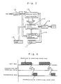
- Fig. 2 is a block diagram of the above-described signal conversion device 2
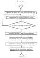
- Fig. 3 is a flowchart thereof
- Fig. 4 shows a figure of timings.
- the serial data which is entered from the code input portion 9 of the above-described input device 1 through the receiver 10, is received by the clock rate from the receiving clock 11, one data unit of which (each make code and break code is defined as one data, respectively) is incorporated into the receiving buffer 12. After incorporating one unit of data, the serial data is converted to the parallel signal to transfer to the transmitting buffer 13.
- the parallel data is converted to the serial data to provide an output with the transmitting clock rate 14 through the driver 15.
- the output of the switching signal for receiving/transmitting is provided from the receiving and transmitting timing generating means 16, as shown in Fig. 4, the output of the switching signal for receiving/transmitting is provided. Namely, after completion of incorporating one unit of data into the receiving buffer 12, the output of the swiching signal is provided to genarate the output of the data from the transmitting buffer 13, simultaneously with wich the data is transferred from the receiving buffer 12 to the transmitting buffer.
- the output of the data from the above-described signal conversion device 2 is entered from the keyboard interface of the computer 3 which is subjected to be controled, and the program operation of the computer 3 is performed according to the input data.
- This computer 3 may be such one that has a keyboard interface, wherein the data from said signal conversion device 2 may be entered into one or more computers. Therefore, for example, the contents of key operation for the input device 1 is converted to the identification character sequence to store in the storage medium beforehand, which is read optionally to transmit the storage data thereof to the computer 3 through the signal code conversion portion 8, the code transmission portion 9 and the signal conversion device 2 to carry out infromation processing depending on the above, while in the mean time, it becomes possible to transmit another storage data to another computer to perform simultaneous operation of another information processing. In addition, direct input of the data from the key operation input portion 4 to the computer 3 may be possible.
- the signal conversion device 2 may be integrated into the main body of the input device 1, or may be an attached equipment of the input device 1.
- this device 2 may be omitted.
- the keyboard operation of routine work may be made to codes to store in the storage madium 6 of the input device, so that the information may optionally be read from the storage medium 6 to operate the computer program in the same way as the keyboard operation by an operator. Therefore, labor saving and unmanned operation may be possible.
- the output of the key operation signal code from the input device 1 to plural computers makes it possibel to control plural computers simultaneously, so that parallel and simultaneous processing of enormous informations may also be possible.
- remote control for a computer in a remote place may also be possible.
- a Input device A Input device
Landscapes
- Engineering & Computer Science (AREA)
- General Engineering & Computer Science (AREA)
- Theoretical Computer Science (AREA)
- Human Computer Interaction (AREA)
- Physics & Mathematics (AREA)
- General Physics & Mathematics (AREA)
- Input From Keyboards Or The Like (AREA)
Abstract
An input device with a keyboard in which a keyboard-input signal is stored in a storage medium, and otionally a signal code, which is read from the storage medium, is converted to a transmission code to enter into a keyboard interface portion of a computer.
Description
- The present invention relates to an input device for a computer with a keyboard, in which input informations with respect to keyboard operation are stored, and the informations may be optionally entered into one or more computers.
- When operation of a computer with a program is carried out by entering with a keyboard, entering is conventionally carried out from a keyboard with respect to each computor, and operation of keys depends on programs of each computer. This makes it necessary to perform keyboard operation with respect to each computer in such a case, for example, that plural computers are used to carry out information processing simultaneously, resulting in that management and operation thereof are complicated.
- The object of the present invention is to provide an input device for a computer which is provided with:
a means for converting an input from each key of a keyboard to an identification code corresponding to the each key,
a memory means for storing the identification code, and
a means for converting the identification code to a transmission code to transmit,
in order to perfoem operation of plural computers by means of one keyboard input device. - Alternatively, another object of the present invention is to provide an input device for a computer according to the above-described input device for a computer, wherein it is provided with a means for performing signal conversion of the transmission code from the transmission means in correspondence with an interface portion of a computer which is subjected to be entered.
-
- Fig. 1 is a blocked diagram with which an example of the present invention is intended to be explained.
- Fig. 2 is a block diagram of a signal conversion device which constructs the present invention.
- Fig. 3 is a flowchart with which an example of the present invention is intended to be explained.
- Fig. 4 is a figure showing timings with which an example of the present invention is intended to be explained.
- Examples of the present invention will be explained in reference to attached drawings as follows.
- Fig. 1 is a whole blocked diagram showing an example of the present invention, wherein 1 is the input device for a computer, 2 is the signal conversion device, and 3 is the computer which is subjected to be controled.
- 4 is the input portion by key operation of said
input device 1, wherein when a signal is entered into theinput portion 4 by key operation of the keyboard, the input signal is converted to an identification character sequence corresponding to the input key in the identification charactersequence conversion portion 5. This identification character sequence is predetermined so as to correspond to all keys on the keyboard. - This identification character sequence is once stored in a
storage medium 6 such as a disk, which is optionally read from the storage medium (7 in the figure). The read identification character sequence is converted to a make/break code which corresponds to the identification character sequence in the signalcode conversion portion 8. This make/break code is defined as make in case of pushing a key or as break in case of releasing a key, in which one key operation is expressed by means of two kinds of code. Concretely speaking, for example, when the return key which is a specific key is operated, the input signal thereof is converted to an identification code (CR), which is stored in the storage medium. On the other hand, when the identification character sequence (CR) is read from the storage medium, it is analyzed to convert to a make code (1C) and a break code (9C) which correspond to the return key in the signalcode conversion portion 8. - On the other hand, in the present invention, a switching means (not shown) makes it possible to directly convert the identification character sequence to the make/break code in the signal
code conversion portion 8 from the above-described identification charactersequence conversion portion 5 without existing the storage medium therebetween. - The make/break conversion code in the above-described signal
code conversion portion 8 is transmitted from thecode transmitting portion 9 to the signal conversion portion 2. In particular, the make code is transmitted from the interface at first, and is subjected to rest in a moment (PAUSE) synchronizing with the computer which is subjected to be controled, after which the break code is transmitted. And then, it is subjected to pause during the time from the break code to transmitting the next make code, which is repeated hereinafter to sequentially transmit the signal code. In addition, this pausing time differs depending on the computer which is subjected to be controled or on the software. - The above-described signal conversion device 2 is for converting the code which is transmitted from the
control computer 1 to the signal (make/break signal) and voltage, communication system, and communication speed which are equivalent to those of the keyboard input device of thecomputer 3 which is subjected to be controled. In this signal conversion device 2, an input terminal is connected to the interface for the telecommunication line of saidinput device 1, and an output terminal is connected to the keyboard interface of thecomputer 3. - Fig. 2 is a block diagram of the above-described signal conversion device 2, Fig. 3 is a flowchart thereof, and Fig. 4 shows a figure of timings.
- At first, the serial data, which is entered from the
code input portion 9 of the above-describedinput device 1 through thereceiver 10, is received by the clock rate from the receiving clock 11, one data unit of which (each make code and break code is defined as one data, respectively) is incorporated into thereceiving buffer 12. After incorporating one unit of data, the serial data is converted to the parallel signal to transfer to the transmittingbuffer 13. - In the transmitting
buffer 13, the parallel data is converted to the serial data to provide an output with the transmitting clock rate 14 through the driver 15. - In addition, from the receiving and transmitting timing generating means 16, as shown in Fig. 4, the output of the switching signal for receiving/transmitting is provided. Namely, after completion of incorporating one unit of data into the
receiving buffer 12, the output of the swiching signal is provided to genarate the output of the data from the transmittingbuffer 13, simultaneously with wich the data is transferred from thereceiving buffer 12 to the transmitting buffer. - The output of the data from the above-described signal conversion device 2 is entered from the keyboard interface of the
computer 3 which is subjected to be controled, and the program operation of thecomputer 3 is performed according to the input data. - This
computer 3 may be such one that has a keyboard interface, wherein the data from said signal conversion device 2 may be entered into one or more computers. Therefore, for example, the contents of key operation for theinput device 1 is converted to the identification character sequence to store in the storage medium beforehand, which is read optionally to transmit the storage data thereof to thecomputer 3 through the signalcode conversion portion 8, thecode transmission portion 9 and the signal conversion device 2 to carry out infromation processing depending on the above, while in the mean time, it becomes possible to transmit another storage data to another computer to perform simultaneous operation of another information processing. In addition, direct input of the data from the keyoperation input portion 4 to thecomputer 3 may be possible. - However, the above-described example is an example of the present invention, so that for example, the signal conversion device 2 may be integrated into the main body of the
input device 1, or may be an attached equipment of theinput device 1. In addition, when the signal conversion function is contained in thecomputer 3 which is subjected to be controled, this device 2 may be omitted. - According to the present invention, for example, the keyboard operation of routine work may be made to codes to store in the
storage madium 6 of the input device, so that the information may optionally be read from thestorage medium 6 to operate the computer program in the same way as the keyboard operation by an operator. Therefore, labor saving and unmanned operation may be possible. - In addition, the output of the key operation signal code from the
input device 1 to plural computers makes it possibel to control plural computers simultaneously, so that parallel and simultaneous processing of enormous informations may also be possible. And optionally, remote control for a computer in a remote place may also be possible. - In addition, in the present invention, it is not necessary to improve already-existing computer programs, so that the cost thereof is cheap.
-
- 4...Input portion by key operation
- 5...Identification character sequence conversion portion
- 6...Storage into disk
- 7...Reading from disk
- 8...Signal code conversion portion
- 9...Code transmitting portion
-
- 2...Signal conversion portion
-
- 3...Commercially available software
-
- a...Input
- b...Serial data
- c...Parallel data
- d...Output
- 10...Receiver
- 11...Receiving clock
- 12...Receiving buffer, serial/parallel
- 13...Transmitting buffer, serial/parallel
- 14...Transmitting clock
- 15...Driver
- 16...Transmitting and receiving timing generation
-
- a...Input data
- b...Transmitting and receiving timing
- c...Transmission data
- d...Receiving by receiving clock rate
- e...Transmitting by transmitting clock rate
-
- a...Receiving of serial data with receiving clock rate
- b...Incorporation of data into receiving buffer
- c...Is one unit of data incorporated?
- d...Conversion of serial data to parallel signal
- e...Transferring data to transmitting buffer
- f...Conversion of parallel signal to serial data
- g...Transmitting by transmitting clock rate
Claims (2)
1. An input device for a computer with a keyboard, which is provided with following means:
a means for converting an input from each key of the keyboard to an identification code corresponding to the each key,
a memory means for storing the identification code,
a means for converting said identification code to a transmission code, and
a means for transmitting said converted code.
a means for converting an input from each key of the keyboard to an identification code corresponding to the each key,
a memory means for storing the identification code,
a means for converting said identification code to a transmission code, and
a means for transmitting said converted code.
2. The input device for a computer according to claim 1, which is provided with a means for performing signal conversion of the transmission code in correspondence with an interface portion of a computer which is subjected to be entered.
Applications Claiming Priority (2)
| Application Number | Priority Date | Filing Date | Title |
|---|---|---|---|
| JP289940/89 | 1989-11-09 | ||
| JP1289940A JPH0638220B2 (en) | 1989-11-09 | 1989-11-09 | Electronic computer automatic input device |
Publications (2)
| Publication Number | Publication Date |
|---|---|
| EP0426945A2 true EP0426945A2 (en) | 1991-05-15 |
| EP0426945A3 EP0426945A3 (en) | 1992-05-27 |
Family
ID=17749713
Family Applications (1)
| Application Number | Title | Priority Date | Filing Date |
|---|---|---|---|
| EP19900111025 Withdrawn EP0426945A3 (en) | 1989-11-09 | 1990-06-11 | Input device for computer |
Country Status (2)
| Country | Link |
|---|---|
| EP (1) | EP0426945A3 (en) |
| JP (1) | JPH0638220B2 (en) |
Cited By (1)
| Publication number | Priority date | Publication date | Assignee | Title |
|---|---|---|---|---|
| EP0869422A2 (en) * | 1997-03-31 | 1998-10-07 | Compaq Computer Corporation | Methods and apparatus for converting remote control signals into computer keyboard signals |
Citations (4)
| Publication number | Priority date | Publication date | Assignee | Title |
|---|---|---|---|---|
| EP0137991A1 (en) * | 1983-09-02 | 1985-04-24 | Mitsubishi Denki Kabushiki Kaisha | Code control system in terminal equipment |
| EP0262226A1 (en) * | 1986-02-06 | 1988-04-06 | Fanuc Ltd. | Method of inputting data |
| EP0284742A2 (en) * | 1987-03-31 | 1988-10-05 | Lexmark International, Inc. | Method and apparatus for processing keystrokes |
| US4779079A (en) * | 1985-09-06 | 1988-10-18 | Hauck Lane T | Multi-purpose computer utility arrangement |
Family Cites Families (5)
| Publication number | Priority date | Publication date | Assignee | Title |
|---|---|---|---|---|
| JPS5315777B2 (en) * | 1973-06-29 | 1978-05-27 | ||
| JPS58176735A (en) * | 1982-04-09 | 1983-10-17 | Fujitsu Ltd | Simple keyboard for personal computer |
| JPS60254350A (en) * | 1984-05-31 | 1985-12-16 | Nec Ic Microcomput Syst Ltd | Data communication control device |
| JPS6386638A (en) * | 1986-09-29 | 1988-04-18 | Nec Corp | Terminal system corresponding to different kinds of computers |
| JPH01233644A (en) * | 1988-03-15 | 1989-09-19 | Fuji Xerox Co Ltd | Network system |
-
1989
- 1989-11-09 JP JP1289940A patent/JPH0638220B2/en not_active Expired - Lifetime
-
1990
- 1990-06-11 EP EP19900111025 patent/EP0426945A3/en not_active Withdrawn
Patent Citations (4)
| Publication number | Priority date | Publication date | Assignee | Title |
|---|---|---|---|---|
| EP0137991A1 (en) * | 1983-09-02 | 1985-04-24 | Mitsubishi Denki Kabushiki Kaisha | Code control system in terminal equipment |
| US4779079A (en) * | 1985-09-06 | 1988-10-18 | Hauck Lane T | Multi-purpose computer utility arrangement |
| EP0262226A1 (en) * | 1986-02-06 | 1988-04-06 | Fanuc Ltd. | Method of inputting data |
| EP0284742A2 (en) * | 1987-03-31 | 1988-10-05 | Lexmark International, Inc. | Method and apparatus for processing keystrokes |
Cited By (4)
| Publication number | Priority date | Publication date | Assignee | Title |
|---|---|---|---|---|
| EP0869422A2 (en) * | 1997-03-31 | 1998-10-07 | Compaq Computer Corporation | Methods and apparatus for converting remote control signals into computer keyboard signals |
| EP0869422A3 (en) * | 1997-03-31 | 1999-12-15 | Compaq Computer Corporation | Methods and apparatus for converting remote control signals into computer keyboard signals |
| EP1862888A2 (en) * | 1997-03-31 | 2007-12-05 | Compaq Computer Corporation | Methods and apparatus for converting remote control signals into computer keyboard signals |
| EP1862888A3 (en) * | 1997-03-31 | 2008-06-04 | Compaq Computer Corporation | Methods and apparatus for converting remote control signals into computer keyboard signals |
Also Published As
| Publication number | Publication date |
|---|---|
| JPH0638220B2 (en) | 1994-05-18 |
| EP0426945A3 (en) | 1992-05-27 |
| JPH03152616A (en) | 1991-06-28 |
Similar Documents
| Publication | Publication Date | Title |
|---|---|---|
| US4425627A (en) | Intelligent prompting terminal apparatus | |
| US4614978A (en) | Office communications system | |
| US5167021A (en) | Multimedia interface device and method | |
| US3980994A (en) | Text editing and display system having text insert capability | |
| CA2060976C (en) | Dce and method for processing data received in a dce allowing multiple operating configurations | |
| US20030146903A1 (en) | Wired keyboard with built-in web camera | |
| EP0426945A2 (en) | Input device for computer | |
| EP0632390B1 (en) | Processor circuit comprising a first processor, and system comprising the processor circuit and a second processor | |
| US4878250A (en) | Image processing system | |
| KR20020024235A (en) | The method for conversion and transmission of user data between a different kind of mobile phone | |
| EP0076902B1 (en) | System for converting data processing information to text processing format and vice versa | |
| EP0240749A2 (en) | Disk controller bus interface | |
| US4547628A (en) | Data transmission system | |
| JPS62262164A (en) | Virtual terminal controller | |
| US5073965A (en) | Image processing system | |
| EP0744048A1 (en) | A device to allow communication between a computer and an external unit | |
| US3566360A (en) | Control system for coordinating operation of a plurality of asynchronously operated peripheral data transmitting and receiving devices | |
| KR0169003B1 (en) | Chip card-read combinded keyboard/write device | |
| KR0123720B1 (en) | Data printing method | |
| KR0182695B1 (en) | Management between host switching module and remote switching module | |
| JPS62187953A (en) | Transmission equipment for test device | |
| JP3296639B2 (en) | Communication switching system device | |
| JPS59127462A (en) | Facsimile equipment | |
| JP2630071B2 (en) | Data transmission / reception method | |
| KR0180668B1 (en) | Data receiving apparatus |
Legal Events
| Date | Code | Title | Description |
|---|---|---|---|
| PUAI | Public reference made under article 153(3) epc to a published international application that has entered the european phase |
Free format text: ORIGINAL CODE: 0009012 |
|
| AK | Designated contracting states |
Kind code of ref document: A2 Designated state(s): DE FR GB |
|
| PUAL | Search report despatched |
Free format text: ORIGINAL CODE: 0009013 |
|
| AK | Designated contracting states |
Kind code of ref document: A3 Designated state(s): DE FR GB |
|
| STAA | Information on the status of an ep patent application or granted ep patent |
Free format text: STATUS: THE APPLICATION IS DEEMED TO BE WITHDRAWN |
|
| 18D | Application deemed to be withdrawn |
Effective date: 19921128 |