EP0425985A2 - Stereoscopic imaging system - Google Patents
Stereoscopic imaging system Download PDFInfo
- Publication number
- EP0425985A2 EP0425985A2 EP90120317A EP90120317A EP0425985A2 EP 0425985 A2 EP0425985 A2 EP 0425985A2 EP 90120317 A EP90120317 A EP 90120317A EP 90120317 A EP90120317 A EP 90120317A EP 0425985 A2 EP0425985 A2 EP 0425985A2
- Authority
- EP
- European Patent Office
- Prior art keywords
- image
- stereoscopic
- lenses
- imaging units
- distance
- Prior art date
- Legal status (The legal status is an assumption and is not a legal conclusion. Google has not performed a legal analysis and makes no representation as to the accuracy of the status listed.)
- Granted
Links
Images











Classifications
-
- H—ELECTRICITY
- H04—ELECTRIC COMMUNICATION TECHNIQUE
- H04N—PICTORIAL COMMUNICATION, e.g. TELEVISION
- H04N19/00—Methods or arrangements for coding, decoding, compressing or decompressing digital video signals
- H04N19/50—Methods or arrangements for coding, decoding, compressing or decompressing digital video signals using predictive coding
- H04N19/597—Methods or arrangements for coding, decoding, compressing or decompressing digital video signals using predictive coding specially adapted for multi-view video sequence encoding
-
- H—ELECTRICITY
- H04—ELECTRIC COMMUNICATION TECHNIQUE
- H04N—PICTORIAL COMMUNICATION, e.g. TELEVISION
- H04N13/00—Stereoscopic video systems; Multi-view video systems; Details thereof
- H04N13/10—Processing, recording or transmission of stereoscopic or multi-view image signals
- H04N13/106—Processing image signals
- H04N13/161—Encoding, multiplexing or demultiplexing different image signal components
-
- H—ELECTRICITY
- H04—ELECTRIC COMMUNICATION TECHNIQUE
- H04N—PICTORIAL COMMUNICATION, e.g. TELEVISION
- H04N13/00—Stereoscopic video systems; Multi-view video systems; Details thereof
- H04N13/10—Processing, recording or transmission of stereoscopic or multi-view image signals
- H04N13/106—Processing image signals
- H04N13/167—Synchronising or controlling image signals
-
- H—ELECTRICITY
- H04—ELECTRIC COMMUNICATION TECHNIQUE
- H04N—PICTORIAL COMMUNICATION, e.g. TELEVISION
- H04N13/00—Stereoscopic video systems; Multi-view video systems; Details thereof
- H04N13/10—Processing, recording or transmission of stereoscopic or multi-view image signals
- H04N13/189—Recording image signals; Reproducing recorded image signals
-
- H—ELECTRICITY
- H04—ELECTRIC COMMUNICATION TECHNIQUE
- H04N—PICTORIAL COMMUNICATION, e.g. TELEVISION
- H04N13/00—Stereoscopic video systems; Multi-view video systems; Details thereof
- H04N13/20—Image signal generators
- H04N13/204—Image signal generators using stereoscopic image cameras
- H04N13/239—Image signal generators using stereoscopic image cameras using two two-dimensional [2D] image sensors having a relative position equal to or related to the interocular distance
-
- H—ELECTRICITY
- H04—ELECTRIC COMMUNICATION TECHNIQUE
- H04N—PICTORIAL COMMUNICATION, e.g. TELEVISION
- H04N13/00—Stereoscopic video systems; Multi-view video systems; Details thereof
- H04N13/20—Image signal generators
- H04N13/296—Synchronisation thereof; Control thereof
-
- H—ELECTRICITY
- H04—ELECTRIC COMMUNICATION TECHNIQUE
- H04N—PICTORIAL COMMUNICATION, e.g. TELEVISION
- H04N13/00—Stereoscopic video systems; Multi-view video systems; Details thereof
- H04N13/30—Image reproducers
- H04N13/366—Image reproducers using viewer tracking
- H04N13/371—Image reproducers using viewer tracking for tracking viewers with different interocular distances; for tracking rotational head movements around the vertical axis
-
- H—ELECTRICITY
- H04—ELECTRIC COMMUNICATION TECHNIQUE
- H04N—PICTORIAL COMMUNICATION, e.g. TELEVISION
- H04N13/00—Stereoscopic video systems; Multi-view video systems; Details thereof
- H04N13/30—Image reproducers
- H04N13/366—Image reproducers using viewer tracking
- H04N13/373—Image reproducers using viewer tracking for tracking forward-backward translational head movements, i.e. longitudinal movements
-
- H—ELECTRICITY
- H04—ELECTRIC COMMUNICATION TECHNIQUE
- H04N—PICTORIAL COMMUNICATION, e.g. TELEVISION
- H04N13/00—Stereoscopic video systems; Multi-view video systems; Details thereof
- H04N13/30—Image reproducers
- H04N13/366—Image reproducers using viewer tracking
- H04N13/376—Image reproducers using viewer tracking for tracking left-right translational head movements, i.e. lateral movements
-
- H—ELECTRICITY
- H04—ELECTRIC COMMUNICATION TECHNIQUE
- H04N—PICTORIAL COMMUNICATION, e.g. TELEVISION
- H04N13/00—Stereoscopic video systems; Multi-view video systems; Details thereof
- H04N13/30—Image reproducers
- H04N13/366—Image reproducers using viewer tracking
- H04N13/38—Image reproducers using viewer tracking for tracking vertical translational head movements
-
- H—ELECTRICITY
- H04—ELECTRIC COMMUNICATION TECHNIQUE
- H04N—PICTORIAL COMMUNICATION, e.g. TELEVISION
- H04N13/00—Stereoscopic video systems; Multi-view video systems; Details thereof
- H04N13/30—Image reproducers
- H04N13/398—Synchronisation thereof; Control thereof
-
- H—ELECTRICITY
- H04—ELECTRIC COMMUNICATION TECHNIQUE
- H04N—PICTORIAL COMMUNICATION, e.g. TELEVISION
- H04N13/00—Stereoscopic video systems; Multi-view video systems; Details thereof
- H04N13/10—Processing, recording or transmission of stereoscopic or multi-view image signals
-
- H—ELECTRICITY
- H04—ELECTRIC COMMUNICATION TECHNIQUE
- H04N—PICTORIAL COMMUNICATION, e.g. TELEVISION
- H04N13/00—Stereoscopic video systems; Multi-view video systems; Details thereof
- H04N13/10—Processing, recording or transmission of stereoscopic or multi-view image signals
- H04N13/106—Processing image signals
- H04N13/15—Processing image signals for colour aspects of image signals
-
- H—ELECTRICITY
- H04—ELECTRIC COMMUNICATION TECHNIQUE
- H04N—PICTORIAL COMMUNICATION, e.g. TELEVISION
- H04N13/00—Stereoscopic video systems; Multi-view video systems; Details thereof
- H04N13/30—Image reproducers
- H04N13/332—Displays for viewing with the aid of special glasses or head-mounted displays [HMD]
- H04N13/337—Displays for viewing with the aid of special glasses or head-mounted displays [HMD] using polarisation multiplexing
-
- H—ELECTRICITY
- H04—ELECTRIC COMMUNICATION TECHNIQUE
- H04N—PICTORIAL COMMUNICATION, e.g. TELEVISION
- H04N13/00—Stereoscopic video systems; Multi-view video systems; Details thereof
- H04N13/30—Image reproducers
- H04N13/332—Displays for viewing with the aid of special glasses or head-mounted displays [HMD]
- H04N13/341—Displays for viewing with the aid of special glasses or head-mounted displays [HMD] using temporal multiplexing
Definitions
- This invention relates to a stereoscopic imaging system for providing stereoscopic images, and particularly to a stereoscopic image system which permits observation of stereoscopic images with less fatigue without producing an unnatural feeling to the observing eyes and without depending on the position of the observing eyes.
- a stereoscopic (three-dimensional) television system which gets stereoscopic images by generating the above-mentioned factors by means of two television cameras and provides the eyes with the images separately, thereby giving the viewer a perception of viewing the stereoscopic object.
- Figs. 11 A, 11 B and 11 C show an example in which one monitor is used.
- the left camera 1 and the right camera 2 take images in which there is a binocular parallax.
- a field change-over signal processing unit 3 produces a synthesized video signal 4 made by alternately arranging frames L with frames R taken by the left and right camera heads 1 and 2.
- An A/D converter 5 converts this video signal into a digital signal, which is stored in a frame memory 6, and a frame number converter 7 re-arranges the digital signal as a video signal 8 provided at a speed twice faster than before.
- a D/A converter 9 converts this video signal 8 (Fig. 1B) in digital form into analog form, and shows the analog video signal on a twice-high-speed scanning monitor 10.
- Liquid crystal glasses 11 open and close liquid crystal shutters synchronized with the frames alternately shown on the twice-high-speed scanning monitor 10 in response to shutter signals 12 and 13 (Fig. 1C) synchronized with the frames produced by the frame number converter 7. Therefore, the left eye sees only the left frames L and the right eye sees only the right frames R.
- a method which, instead of the liquid crystal shutters, uses polarized light shutters, placed in front of the monitor screen or a projection lens of a video projector, operates the polarized light shutters by turns in synchronism with the left and right frames, and man can separate the left and right images and obtain a stereoscopic image by wearing polarizing glasses using polarizing lenses, the polarizing directions of which differ between the left and right lenses.
- the relative position of the two camera heads 1, 2 is set in the following two ways (Figs. 2 and 6).
- One method is that as shown in Fig. 2, the two camera heads are arranged with their optical axes oriented in parallel. If an object, from which iamges are obtained is located in front of the two parallel camera heads 1, 2, the images are formed on image-forming planes 17, 18 by lenses 15, 16.
- the sizes and directions of images I and r on the image-forming planes are indicated by leader lines.
- the two images I and r are displayed alternately on the monitor screen 19 as shown in Fig. 13, and the images are caught by a man's eyes 20, 21.
- the left eye views the image 1 seen from the left hand side, while the right eye views the image r seen from the right hand side.
- a synthesized image 22 that can be seen by the binocular parallax is located in front of the monitor screen 19.
- Fig. 2 if the object 12 is moved along the intermediate axis between the two camera heads 1, 2 to a point at infinity, the images of the object are formed at the central points of the left and right image-forming planes 17, 18.
- the point at infinity is located at the center of the monitor screen 19.
- positions k and m of the point p (x,y) on the image-forming planes are expressed by the following equations.
- b is the distance between the centers of the image-forming planes 17, 18, d is the distances from the lens centers to the image-forming planes, and s is the size of the image-forming planes.
- S the size of the monitor screen
- D the distance from the eyes of the observer to the monitor screen
- E the space between the eyes by E
- the position of a synthesized stereoscopic image P(X,Y) is expressed as follows. The positions K, M of the left and right rather than the screen size are first shown.
- Another method of setting the relative position of the camera heads 1, 2 is to converge the optical axes of the cameras as shown in Fig. 6.
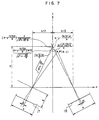
- the image obtained by this method is expressed by using arrangements in Figs. 7 and 8.
- the positions k and m of the point p(x,y) on the image-forming planes are expressed as follows.
- both X and Y subject to the effect of x and y, are not in a simple proportional relationship. Therefore, the images taken by the left and right camera heads 1, 2 have an image distortion in addition to a transverse difference between them caused by the binocular parallax, thus posing a difficulty in obtaining a stereoscopic vision.
- a stereoscopic camera is constructed such that normals of the image-forming planes of said two cameras are arranged in parallel, that a distance between the optical centers of lenses of said two cameras is shorter than a distance between the centers of image-forming planes of said two cameras, that both a ratio of the distance which is a remainder of subtraction of the lenses spacing from the image-forming planes spacing to the distance between the eyes of said observer and a ratio of the distance from said image-forming planes to the optical centers of the lenses to the distance from said observer to the screen are substantially
- optical centers 28, 29 of lenses of the left and right camera heads are converged from the center lines of the image-forming planes 17, 18 so that straight lines connecting between the center points of the image-forming planes 17, 18 and the optical centers 28, 29 of the lenses intersect each other on the y axis at a point which is the distance a away in front of the lens plane.
- the values of k and m which define the position of the image of the point p (x,y) can be obtained as follows.
- the position of the synthesized stereoscopic image P(X,Y) is in proportion to the position of the object p(x,y) and that an image without distortion can be reproduced.
- the proportional constant, which indicates an enlargement ratio of the space is determined by a ratio (D/a) between the distance D from the position of the obserber to the monitor image plane and the distance a from the lens plane to the intersection of the optical axes of the two camera heads.
- the space d between the camera heads needs to be set at a value obtained by the following equation. Therefore,
- the d is a value determined by the focal length of the lenses and by focus adjustment, but since the effect of focus adjustment is small, the d can be so set in design as to be determined by the focal length.
- a reproduced stereoscopic image is free from distortion, so that the unnaturalness due to difference in the vertical length of images, described in Fig. 10, does not occur.
- an image is obtained of a quadrilateral present on a plane perpendicular to the optical axes of the camera heads.
- the image-forming planes 17, 18 are parallel with the quadrilateral, so that the images on the image-forming planes 17, 18 are homologous quadrilaterals which are point-symmetric with the quadrilateral in relation to the optical centers 28, 29 of the lenses.
- the ratio in size is determined by a ratio of normal distances from the optical centers 28, 29 of the lenses to the respective quadrilaterals.
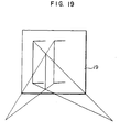
- the same lengths are set for the normal distances from the lens centers 28, 29 to the image-forming planes 17, 18 in the left and right camera heads. Therefore, quadrilaterals formed on the left and right image-forming planes 17, 18 are the same in size. As a result, the vertical sides of the two quadrilaterals are the same. Consequently, as shown in Fig. 19, in the stereoscopic image formed, the lengths of the vertical lines are identical, so that there is no unnaturalness in the image and the observer can get the impression of three dimensions (depth) in viewing the image.
- the value of d changes.
- the distance a from the optical centers of the lenses to the intersection of the optical axes of the camera heads changes to a .
- the stereoscopic camera of this invention is constructed such that two television cameras are arranged with the normals of the image-forming planes thereof oriented in parallel, that the stereoscopic camera is provided with a signal processing unit for processing signals so that the space between the centers of the two lenses is larger than the space between the image-forming points corresponding to the image centers of the two image-forming planes, and that the lines connecting the lens centers with the image-forming points corresponding to the image centers are arranged to intersect each other in front of the stereoscopic camera.
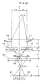
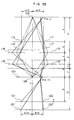
- the points 136, 137 at which straight lines connecting a point which is the distance an away in front of the two television cameras with the lens centers of the television cameras intersect the image-forming planes 118, 119 are defined as the center points of the images.
- An image is reproduced so that the image center points 136, 137 coincide with the center point 138 of the monitor screen 120.
- the position of the reproduced stereoscopic image P(X,Y) of the point p (x,y) can be obtained as shown below.
- the space b between the image center points can be found by geometrical relations shown in Fig. 23.
- the positions mL and mR of the images are:
- the position of the stereoscopic image P(X,Y) is obtained as:
- a ratio between the distance D from the observer to the monitor screen and the distance d from the lenses to the image-forming planes is equal to a ratio between the size S of the monitor screen and the size s of the image-forming planes, as shown below.
- the reproduced stereoscopic image P(X,Y) is represented E/e times larger than the original point p, and is perfectly isotropic. Therefore, an accurate stereoscopic image without distortion can be obtained. If the space e between the cameras is made equal to the space between the eyes of the observer, the reproduced stereoscopic image can represents the environment in front of the stereoscopic camera accurately as it is. If a stereoscopic camera with a small camera spacing e is used while maintaining the conditions expressed by Eqs. (138), (139), a reproduced image can be enlarged.
- E/e is defined as the stereoscopic image enlargement ratio v.
- the observer observes at a position away from the monitor screen by the distance D obtained by multiplying the distance from the lens centers of the cameras to the image-forming planes by the ratio of the monitor screen size S to the image-forming plane size s.
- the distance a from the intersection of the optical axes of the two cameras to the line connecting the optical centers of the camera lenses needs to be set to be equal to a product of the distance D from the observer to the monitor screen and the ratio between the camera spacing e and the observer's binocular space E, that is to say, the reciprocal of the stereoscopic image enlargement ratio v.
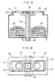
- two television cameras 30, 31 are combined by a connecting member 32 into a single body and used as a stereoscopic camera.
- Mount members 33, 34 of television cameras 30, 31 have formed at their openings threads 37, 38 for mounting lens tubes 35, 36.
- images are formed on the image-forming elements 39, 40 in the television camera. It ought to be noted that the positions of the centers of the mounting threads are not on the axes of the image-forming elements 39, 40, but located shifted towards the connecting member 32.
- Figs. 13 and 14 show another embodiment of this invention.
- lens mounts 41, 42 are so constructed as to be slidable. More specifically, the lens mounts 41, 42 are each made by bending a thin plate and the ends of the plate are bent towards the inside. The bent portions are fitted into the grooves provided at the end plates 43, 44 of the television cameras, and are slidable.
- Rack gears 45, 46 are provided at part of the lens mounts 41, 42 and engage with a pinion 47.
- the pinion 47 is connected with a knob 49 with the intermediary of a shaft 48.
- a shading material 50 is attached to the inside of the lens mounts 41, 42 to cut off the external light.
- the left and right lens mounts 41, 42 are caused to slide the same distance by the work of the pinion 47 and the racks 46, 47, so that the distance between the lenses can be changed easily. Therefore, if the distance between the observer and image-reproducing means changes, the adequate conditions can be obtained to produce a correct stereoscopic image only by correcting the distance between the lenses.
- the stereoscopic camera of this embodiment can be used for video recording at theaters or remote control of a manipulator, etc.
- the stereoscopic camera if made in a small size, will be effective in surgery using a TV.
- a natural stereoscopic vision without distortion can be obtained, so that the fatigue of the observer can be mitigated and he can continue observation for a long time. Furthermore, according to this invention, even when the position of the observer in relation to the image-reproducing means changes, the lens position can be adjusted so that the observer can get the impression of depth or three dimensions from a synthesized image, and the fatigue of the observer can be lessened.
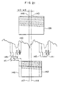
- Fig. 21 shows a first method of shifting the image center on the image-forming plane.
- the image-forming plane is scanned on every other scanning line, and a video signal 140 is thereby obtained.
- a horizontal or vertical synchronizing signal 141 is put in place of the portion of the video signal corresponding to that interval.
- the monitor screen 142 the screen is scanned from the point after the elapse of a fixed time t from when the synchronizing signal is given, thereby changing the video signal into variations of light.
- the center 143 of the image-forming plane substantially agrees with the center 144 of the monitor screen.
- a synchronizing signal 145 made to occur a little earlier than normal is combined with the video signal 140, it follows that the portion of the video signal advanced earlier than normal is scanned, and therefore, an image of a frame 146 is shown on the monitor screen 142. Therefore, on the monitor screen 146, the image shifts to right. As a result, the image center 147 of the frame 146 comes to correspond to the center of the image shifted to left on the image-forming plane 139. If the synchronizing signal is delayed, the image shifts to left, so that the image center on the image-forming plane 139 shifts to right.
- the timing of the synchronizing signal is either advanced or delayed relative to the normal state, and therefore, it is possible to adjust the position of the image center on the image-forming plane.
- Fig. 24 shows a synthesized signal 148 for a stereoscopic vision, in which signals from the left and right cameras are combined alternately.
- the ranges indicated by L are the video signal by the left camera and the ranges indicated by R are the video signal by the right camera.
- the horizontal synchronizing signals for the left and right cameras are shifted in the opposite directions across the wide vertical synchronizing signals, and a horizontal scanning signal 149 causes horizontal scanning to start after a fixed time t since a horizontal synchronizing signal is given.
- the first horizontal scanning starts after passage of time t 2 since a vertical synchronizing signal is given.
- the relation of t, and t ⁇ is set so that the period of the sawtooth waves is constant.
- a color burst signal of the horizontal synchronizing signal is omitted.
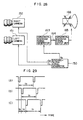
- Fig. 25 shows an embodiment by which the synchronizing signal of the stereoscopic camera is shifted.
- a synchronizing signal generates three kinds of pulse signals, the phase shifts of which are shown in (A), (B), and (C) of Fig. 28.
- Synchronized with synchronizing signals C L and C R provided by the synchronizing signal generator 150, a left camera 151 and a right camera 152 generate video signals 153, 154 and send the signals to synchronizing signal synthesizers 155, 156.
- the synchronizing signal synthesizers 155, 156 combine the video signals 153, 154 with synchronizing signals S L , S R provided by the synchronizing signal generator 150, and output synthesized video signals 157, 158.
- a stereoscopic synthesizer 159 generates a synthesized stereoscopic video signal 160 formed by arranging synthesized video signals 157, 158 alternately, and outputs the synthesized signal.
- the synchronizing signal generator 150 outputs a pulse signal (B) on the lines of synchronizing signals C R , C L for the television cameras. To shift the image center to left, it is only necessary to send a pulse signal (A) leading the pulse signal (B) as the synchronizing signal S L or S R , and similarly, to shift the image center to right, it is only necessary to send a pulse signal (C) lagging the pulse signal (B) as the synchronizing signal S L or S R . By adjusting phase shifts tp and t d , the position of the image center can be selected arbitrarily.
- a second method of shifting the image center is to change time t from when a horizontal synchronizing signal is issued until scanning is started.
- the synchronizing signals are incorporated therein at normal timing, but as for time t from when a horizontal synchronizing signal is given until scanning is started by a horizontal scanning signal, there is difference between t L and t R .
- switchover is done between time t L and t R in synchronism with the video signals of the left and right television cameras. Therefore, the same result can be achieved by the horizontal scanning signal as with the horizontal scanning signal 149.
- Fig. 28 shows an embodiment using the above- mentioned second method.
- the synchronizing signal generator 150 sends synchronizing signals C R , C L to the television cameras 151, 152. Though this is not illustrated, the video signals of the television cameras 151, 152 are combined with the synchronizing signals by ordinary method, and the synthesized signals are sent as a synthesized stereoscopic video signal to the monitor.
- the synchronizing signal generator 150 sends a horizontal synchronizing signal S h to a horizontal scanning signal generator 163 of the monitor. This generator generates sawtooth waves 164, which are amplified by a horizontal scanning signal output unit 165 and used to drive a horizontal deflection coil 166.
- the synchronizing signal generator 150 generates pulse signals whose phases are shifted as indicated by (A), (B) and (C) of Fig. 29, outputs the pulse signals (B) on the lines of synchronizing signals C R , C L alternately, and outputs a pulse signal (B) or (C) alternately on the line of output S h to the horizontal scanning signal generator 163 in synchronism with the synchronizing signals C R and C L . Therefore, the video signals of the left and right television cameras correspond to the horizontal synchronizing signal (A) or (C), and the positions of the image centers of the left and right television cameras can be changed individually by the phase shifts tp and t d .
- Fig. 30 shows a still another embodiment of this invention.
- Fig. 31 shows waveforms at various parts.
- the method illustrated here is to adjust the timing of the horizontal scanning signal based on a synthesized stereoscopic video signal 167 sent from the television cameras.
- a synchronizing signal separator 168 separates the horizontal synchronizing signal 169 and the vertical synchronizing signal 170 from the synthesized stereoscopic video signal 167.
- the horizontal and vertical synchronizing signals 169, 170 are input into signal delay units 171, 172, where the signals are added with delay time to become horizontal synchronizing signals 173, 174.
- the horizontal synchronizing signals 173, 174 are input into the horizontal scanning signal generator 163, which generates sawtooth waves 164, which in turn amplified by the horizontal scanning signal output unit 165 and used to drive the horizontal deflection coil 166.
- Delay times t 4 - and t 6 from the horizontal synchronizing signal are switched over from one to another each time a vertical synchronizing signal 170 is input into the signal delay unit 171, and therefore, the left and right video signals correspond to the delays of the horizontal synchronizing signals.
- the delay times t 3 and t 5 from the vertical synchronizing signal have only to be set so that their pulse spacings are constant.
- a third method for shifting the image center is to use an image memory.
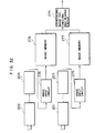
- Video signals obtained by two television cameras are made digital signals through A/D conversion. as shown in Fig. 32, when the digital video signals are input into image input circuits 275, 276, the video signals are recorded in image memories 277, 278.
- a stereoscopic image synthesizing and reading circuit 279 reads video signals from the two image memories 277, 278 alternately and synthesizes a video signal for stereoscopic vision. In this process, by changing the start address for reading the image memories, the position of the image is shifted. For example, to advance video signals, the leading portion of the image memory is skipped and reading is started in the middle of the memory.
- reading is started at a portion just before the end of the image memory, and when the end point is reached, the reading process returns to the start address or a dummy signal is added at the leading portion of the memory. In this way, video signals can be delayed.
- the enlargement ratio of a reproduced stereoscopic image is determined by a ratio between the space E between the eyes of the observer and the space e of the two television cameras. Since the binocular space E is constant for a certain observer, it is only necessary to change the space e between the two television cameras. In this step, it is required to abide by the two conditions mentioned earlier.
- the condition shown by Eq. (142) is not directly related to changing the e and is kept as it is.
- the condition shown by Eq. (145) indicates that if E and D are fixed, the ratio between a and e must be fixed.
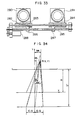
- Fig. 33 shows an embodiment of means for adjusting the space e of the cameras.
- Two television cameras 280, 281 are fixed on slide bases 283, 284 supported by a slide rail 282.
- the slide bases are made to slide in the opposite directions by a screw rod 285 having threads in the opposite lead directions (LH and RH) formed at both ends thereof and by female screws 286, 287 engaging with the threads of the screw rod.
- the screw rod 285 is driven by a motor 288.
- the position of the observer relative to the monitor screen are closely related to the space, the sizes of the images and image-forming planes, and the lens focal length of the television cameras.
- being confined to a fixed position is often not desirable because the freedom of action is lost.
- the moving distance l m of the positions of the images of p(x,y) on the image-forming planes is
- the moving distance tm of the image on the monitor screen 120 is obtained as follows. In Fig. 37, it is assumed that there is a straight line 189 dividing the distance from the image-forming planes 118, 119 to the monitor screen into a ratio between the size s of the image-forming planes and the size S of the monitor screen. If 190, 191 or 190", 191 represent the intersections of the straight line 189 and the lines connecting the image centers 136, 137 or 136'', 137" with the center 138 of the monitor screen, the straight lines connecting the positions of the images on the image-forming planes with the corresponding position of the image on the monitor screen pass through the intersections 190, 191 or 190'', 191 .
- the distance t c between 190 and 190 or between 191 and 191 is obtained as:
- Eq. (174) is always equal to X. If, as shown above, the condition shown by Eq. (174) as well as the conditions shown by Eqs. (142), (143) is satisfied, the position of the image does not change even if the observer moves transversely.
- the condition of Eq. (174) can be expressed by using Eq. (145) as follows.
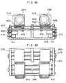
- Figs. 42 and 43 show an embodiment of the stereoscopic camera 297.
- Two television cameras 298, 299 are mounted on side bases 402, 403 supported by slide levers 400, 401.
- the female screws 404, 405 attached to the slide bases 402, 403 engage with screw rods 406, 407.
- the position of the slide bases 402, 403 can be changed independently. Since sensors 410, 411 for position detection are interlocked with the screw rods 406, 407 with the intermediary of gears 412, 413, and the slide bases 402, 403 can be positioned at specified positions by means of a position servo or the like.
- space adjusting means similar to the one shown in Fig. 30.
- This space adjusting means is used only to adjust the space between the lenses.
- the lenses used here are electric telephoto lenses 414, 415.
- the space between the lenses 414, 415 can be adjusted by the screw rod 285 having LH and RH threads formed on the opposite sides thereof.
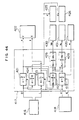
- Fig. 44 shows a control block diagram.
- a magnetic sensor control unit 416 outputs signals representing the distance D from the observer and the screen and the transverse moving distance L relative to the center line of the monitor screen, and input into an arithmetic and control unit 417.
- the observer's binocular space E and the enlargement ratio of the stereoscopic image are input into the arithmetic and control unit 417.
- the arithmetric and control unit 417 obtains e from signals of E and ⁇ at an arithmetic block 419, and outputs e to a controller 420 of the television camera space adjusting unit to set the e.
- An arithmetic block 421 obtains a from signals of D, and outputs a to a control unit 422 for the robot.
- An arithmetic block 423 obtains t from L and f , and outputs l to the control unit 422 for the robot.
- the robot 298 moves so that the position of the stereoscopic camera 297 becomes predetermined values of a and 1.
- An arithmetic block 424 obtains the distance d between the optical centers of the lenses and the image-forming planes from the image-forming plane size a and the monitor screen size S, which have been predetermined. and sends the distance d to the controllers 425, 426 for zoom lenses in order to adjust the optical system.
- An arithmetic block 427 obtains the moving distance 1 s of the image-forming planes from data on a , d , and 1. From the result of this as wellas the value of e , arithmetic blocks 428, 429 obtain the positions X R and X L , which data are then input into position controllers 430, 431, which control the television cameras to move to a specified position.
- the space of the lenses of the television cameras can be adjusted, the enlargement ratio v of the stereoscopic image, and the stereoscopic image is prevented from being distorted or moved when the observer changes his position.
- video signals of two television cameras can be shifted in parallel, so that an accurate stereoscopic vision without distortion can be obtained.
- the observer is away from the specified position, he can get a correct stereoscopic image.
Landscapes
- Engineering & Computer Science (AREA)
- Multimedia (AREA)
- Signal Processing (AREA)
- Testing, Inspecting, Measuring Of Stereoscopic Televisions And Televisions (AREA)
Abstract
Description
- This invention relates to a stereoscopic imaging system for providing stereoscopic images, and particularly to a stereoscopic image system which permits observation of stereoscopic images with less fatigue without producing an unnatural feeling to the observing eyes and without depending on the position of the observing eyes.
- Among many factors by which a man gets a stereoscopic vision are the perception of the positional difference of the images in the two eyes due to the difference in the position of the left and right eyes, i.e. the binocular parallax, and the convergence-divergence movements of the eyes, i.e. slightly moving the eyes closer to each other and away from each other when viewing an object. A stereoscopic (three-dimensional) television system has been developed which gets stereoscopic images by generating the above-mentioned factors by means of two television cameras and provides the eyes with the images separately, thereby giving the viewer a perception of viewing the stereoscopic object. As means for providing a man with the images, there are a method in which two monitors are arranged to give separate images to each eye, and a method by which the left and right images are superimposed on one monitor and the images are separated by polarization of light or by an electronic shutter. Figs. 11 A, 11 B and 11 C show an example in which one monitor is used. In Fig. 1A, the
left camera 1 and theright camera 2 take images in which there is a binocular parallax. A field change-oversignal processing unit 3 produces a synthesizedvideo signal 4 made by alternately arranging frames L with frames R taken by the left andright camera heads D converter 5 converts this video signal into a digital signal, which is stored in aframe memory 6, and aframe number converter 7 re-arranges the digital signal as avideo signal 8 provided at a speed twice faster than before. A D/A converter 9 converts this video signal 8 (Fig. 1B) in digital form into analog form, and shows the analog video signal on a twice-high-speed scanning monitor 10. Liquid crystal glasses 11 open and close liquid crystal shutters synchronized with the frames alternately shown on the twice-high-speed scanning monitor 10 in response toshutter signals 12 and 13 (Fig. 1C) synchronized with the frames produced by theframe number converter 7. Therefore, the left eye sees only the left frames L and the right eye sees only the right frames R. Owing to the effect of the binocular parallax, a man can perceive a stereoscopic image. A method is possible which, instead of the liquid crystal shutters, uses polarized light shutters, placed in front of the monitor screen or a projection lens of a video projector, operates the polarized light shutters by turns in synchronism with the left and right frames, and man can separate the left and right images and obtain a stereoscopic image by wearing polarizing glasses using polarizing lenses, the polarizing directions of which differ between the left and right lenses. - Conventional stereoscopic vision technoligies are discussed in detail in pages 205 to 223 of Nikkei Electronics No. 444 (April 4, 1988) and in
pages 1 to 31 of Seimitsu Kogaku bulletin (the Journal of the Japan Society of Precision Engineering), 54/2/1988. - In the meantime, the relative position of the two
camera heads parallel camera heads planes lenses - The two images I and r are displayed alternately on the
monitor screen 19 as shown in Fig. 13, and the images are caught by a man'seyes image 1 seen from the left hand side, while the right eye views the image r seen from the right hand side. As a result, a synthesizedimage 22 that can be seen by the binocular parallax is located in front of themonitor screen 19. In Fig. 2, if theobject 12 is moved along the intermediate axis between the twocamera heads planes monitor screen 19 of Fig. 3, the point at infinity is located at the center of themonitor screen 19. When the object at the infinite-point moves to left or right, since the rays of light from the object are parallel rays, difference in parallax does not occur between the images I and r . Therefore, the points at infinity are distributed on themonitor screen 19, and normally, a stereoscopic image of an object not present at a point of infinity is formed in front of themonitor screen 19. The area between the paralleloptical axes camera heads optical axes monitor screen 19, and the breadth is also condensed. In consequence, the images are distorted, so that a stereoscopic image cannot be represented correctly. If various lengths are denoted by symbols as shown in Fig. 4, positions k and m of the point p (x,y) on the image-forming planes are expressed by the following equations.

planes 

- Therefore, the position of P(X,Y) is given as:


- From Eq. (5), it is understood that owing to the effect of the value of y, X comes closer to zero as y approaches infinity. It is obvious from Eq. (6) that as y approaches infinity, Y comes closer to A. From Eqs. (5), (6), it follows that the actual point p (x,y) is deformed and reappears at the point P(X,Y) of the stereoscopic image, so that a natural feeling of three dimensions cannot be obtained.
- Another method of setting the relative position of the
camera heads 
- Likewise, from Fig. 8,

- The relation between the
monitor screen 19 on which these demensions are shown and theeyes 

- In consequence, both X and Y, subject to the effect of x and y, are not in a simple proportional relationship. Therefore, the images taken by the left and
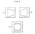
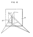
right camera heads - Furthermore, there is another problem. When an object is selected which is in a square shape as seen from the front side, an image obtained by the image-forming
plane 17 at left is a trapezoid with the right side tapering down as shown in Fig. 9. On the other hand, the image obtained by the image-formingplane 18 at right is a trapezoid with the left side tapering down. If these two images are shown superimposed on themonitor screen 19, an image with a binocular parallax results with the corresponding vertical lines different in length. In this case, if the left sides of these squares are taken for example as shown in Fig. 10, the synthesizedimage 27 is not synthesized correctly because these two sides have different lengths in the vertical direction. To be more specific, it is unnatural to obtain a stereoscopic image by synthesizing images of different sizes into a whole image by the work of the brain, and if this is done, the observer will be fatigued. - According to a first aspect of this invention, in order to achieve the above object, in a stereoscopic image system by which it is possible to see a stereoscopic image by parallax by reproducing two kinds of images, between which images there is parallax and which were taken by two cameras, on a screen of image-reproducing means and observing the images by the observer in such a manner that the left and right eyes observe only the images taken by the corresponding cameras out of the images shown on said screen, a stereoscopic camera is constructed such that normals of the image-forming planes of said two cameras are arranged in parallel, that a distance between the optical centers of lenses of said two cameras is shorter than a distance between the centers of image-forming planes of said two cameras, that both a ratio of the distance which is a remainder of subtraction of the lenses spacing from the image-forming planes spacing to the distance between the eyes of said observer and a ratio of the distance from said image-forming planes to the optical centers of the lenses to the distance from said observer to the screen are substantially equal to a ratio of the size of images on said image-forming planes to the size of an image on said screen.
- The operating principle of a stereoscopic image system of the above-mentioned construction will be described with reference to the accompanying drawings.
- In Fig. 15,
optical centers planes planes optical centers 

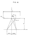
- If this image is synthesized as shown in Fig. 16, the positions K, M of the image on the
monitor screen 19 are expressed as follows.

- If the space between the eyes is denoted by E, the distance from the position of the eyes to the
monitor screen 19 denoted by D, the position of a stereoscopic image P (X,Y) is obtained as:
- Various dimensions are determined so as to satisfy the following relation:


- Thus, X and Y are given as:


- From the above results, it is clear that the position of the synthesized stereoscopic image P(X,Y) is in proportion to the position of the object p(x,y) and that an image without distortion can be reproduced. The proportional constant, which indicates an enlargement ratio of the space is determined by a ratio (D/a) between the distance D from the position of the obserber to the monitor image plane and the distance a from the lens plane to the intersection of the optical axes of the two camera heads. Based on the above-mentioned supposition, the distance D from the human eyes to the monitor screen needs to be set at a value obtained by the following equation.

- The space d between the camera heads needs to be set at a value obtained by the following equation.


- The d is a value determined by the focal length of the lenses and by focus adjustment, but since the effect of focus adjustment is small, the d can be so set in design as to be determined by the focal length.
- According to this method, a reproduced stereoscopic image is free from distortion, so that the unnaturalness due to difference in the vertical length of images, described in Fig. 10, does not occur. Let us suppose that an image is obtained of a quadrilateral present on a plane perpendicular to the optical axes of the camera heads. As shown in Figs. 17, 18, the image-forming
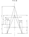
planes planes optical centers optical centers planes planes - When zoom lenses are used or the lenses are replaced with telephoto lenses, the value of d changes. In this case, as shown in Fig. 20, if d changes to d , the distance a from the optical centers of the lenses to the intersection of the optical axes of the camera heads changes to a . At this time,


- The following e is made by substituting a and d in Eq. (22) by a and d by utilizing Eqs. (22) and (24).


- Therefore, in Eqs. (19), (20), by substituting e, d, and y with e', d', and y', we can obtain:


- Therefore,

- From the above results, we find that when the lenses are replaced with lenses with long focal length, the value of X remains unchanged, while the value of Y comes closer to the object by the extended amount of the focal length, and is condensed in inverse proportion to the focal length. As a result, the observer can see the object enlarged as if it were closer to him, but gets a reduced impression of depth.
- According to a second aspect of this invention, in order to achieve the above object, the stereoscopic camera of this invention is constructed such that two television cameras are arranged with the normals of the image-forming planes thereof oriented in parallel, that the stereoscopic camera is provided with a signal processing unit for processing signals so that the space between the centers of the two lenses is larger than the space between the image-forming points corresponding to the image centers of the two image-forming planes, and that the lines connecting the lens centers with the image-forming points corresponding to the image centers are arranged to intersect each other in front of the stereoscopic camera.
- As shown in Fig. 23, two television cameras are arranged in parallel, the
points planes center point 138 of themonitor screen 120. The position of the reproduced stereoscopic image P(X,Y) of the point p (x,y) can be obtained as shown below. The space b between the image center points can be found by geometrical relations shown in Fig. 23.
- Therefore,

- The positions mL and mR of the images are:


- From the size s of the image-forming planes and the positions ML and MR of the image on the
monitor screen 120 are given by

- The position of the stereoscopic image P(X,Y) is obtained as:


- From Eq. (130),

- From Eqs. (129), (131),

- From Eqs. (125), (126),


- From Eqs. (127), (128), (133), (134),


- From Eqs. (132), (135), (136),


- Let us here suppose that a ratio between the distance a from the television camera lenses to the intersection of the optical axes and the distance d from the lenses to the image-forming planes is equal to a product of a ratio between the camera spacing e and the distance of the observer's eyes and a ratio between the monitor screen size S and the imaae-formina olane size s .


- From Eqs. (131), (136),

- Substitutinq Eq. (138) into Eq. (140),

- Suppose here that a ratio between the distance D from the observer to the monitor screen and the distance d from the lenses to the image-forming planes is equal to a ratio between the size S of the monitor screen and the size s of the image-forming planes, as shown below.

- Substituting Eq. (142) into Eq. (141),

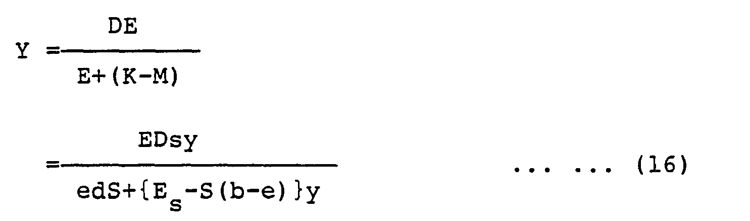
- The reproduced stereoscopic image P(X,Y) is represented E/e times larger than the original point p, and is perfectly isotropic. Therefore, an accurate stereoscopic image without distortion can be obtained. If the space e between the cameras is made equal to the space between the eyes of the observer, the reproduced stereoscopic image can represents the environment in front of the stereoscopic camera accurately as it is. If a stereoscopic camera with a small camera spacing e is used while maintaining the conditions expressed by Eqs. (138), (139), a reproduced image can be enlarged.
- Conversely, if a stereoscopic camera with a large e is used, the reproduced stereoscopic image is reduced in size. At this time, the linearity is maintained.
- If E/e is defined as the stereoscopic image enlargement ratio v.

- From Eqs. (138), (142), and (144),

- Therefore, from Eqs. (144), (145), two conditions for obtaining a stereoscopic image without distortion can be expressed as follows.
- The observer observes at a position away from the monitor screen by the distance D obtained by multiplying the distance from the lens centers of the cameras to the image-forming planes by the ratio of the monitor screen size S to the image-forming plane size s.
- The distance a from the intersection of the optical axes of the two cameras to the line connecting the optical centers of the camera lenses needs to be set to be equal to a product of the distance D from the observer to the monitor screen and the ratio between the camera spacing e and the observer's binocular space E, that is to say, the reciprocal of the stereoscopic image enlargement ratio v.
-
- Figs. 1 A, 1B, and 1 C are respectively a block circuit diagram, a video signal waveform diagram and a shutter signal waveform diagram, which show an example of the conventional stereoscopic image system;
- Figs. 2 to 5 are diagrams showing a first optical system of the conventional stereoscopic image apparatus;
- Fig. 2 shows the imaging optical system;
- Fig. 3 shows the observation optical system of reproduced images;
- Fig. 4 shows the geometric arrangement of said imaging optical system;
- Fig. 5 shows the geometric arrangement of said observation optical system;
- Figs. 6 to 10 are diagrams showing a second optical system of the conventional stereoscopic imaging apparatus;
- Fig. 6 shows the imaging optical system;
- Figs. 7 and 8 show the geometric arrangements of the imaging optical system of Fig. 6;
- Figs. 9 and 10 are diagrams for explaining the problems of the second optical system;
- Figs. 11 to 20 are diagrams showing an embodiment of this invention;
- Figs. 11 to 14 are perspective and front views showing the construction of the camera;
- Figs. 15 to 20 are diagrams showing the geometric arrangement of the imaging optical system;
- Fig. 16 is a geometric arrangement diagram of the observation optical system of reproduced images;
- Figs. 17 to 19 are diagrams for explaining the effect of said embodiment;
- Figs. 21 to 24 are diagrams showing the stereoscopic image system according to another embodiment of this invention;
- Figs. 21 and 24 are diagrams for explaining a video signal and its operation;
- Figs. 22 and 23 are diagrams showing the geometric arrangements of the imaging system and observation system according to this another embodiment;
- Figs. 25 to 27 are diagrams showing a further embodiment of this invention;
- Fig. 25 is a block diagram showing the circuit configuration;
- Fig. 26 is an operation waveform diagram;
- Fig. 27 is a diagram for explaining a video signal and its operation;
- Figs. 28 and 29 are diagrams showing another embodiment of this invention;
- Fig. 28 is a block diagram showing the circuit configuration;
- Fig. 29 is an operation waveform diagram;
- Figs. 30 and 31 are diagrams showing a still further embodiment of this invention;
- Fig. 30 is a block diagram showing the circuit configuration;
- Fig. 31 is an operation waveform diagram;
- Figs. 32 to 39 are diagrams yet another embodiment of this invention;
- Fig. 32 is a block diagram showing the circuit configuration;
- Fig. 33 is a front view showing the moving mechanism of the imaging optical system;
- Figs. 33 to 39 are diagrams showing the geometric optical arrangement of this yet another embodiment;
- Figs. 40 to 44 are diagrams showing an additional embodiment of this invention;
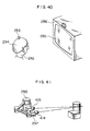
- Fig. 40 is a perspective view for explaining the positional relation between the video monitor screen and the observer;
- Fig. 41 is a perspective view showing the arrangement of the imaging system;
- Figs. 42 and 43 are a front view and a plan view showing the mechanism for moving the imaging optical system; and
- Fig. 44 is a block circuit diagram showing the circuit configuration.
- An embodiment according to said first aspect of this invention will be described with reference to the accompanying drawings.
- Those parts of this embodiment which are identical with these of the prior are designated by the same reference numerals and description of such parts will be omitted.
- As shown in Figs. 11 and 12, two
television cameras member 32 into a single body and used as a stereoscopic camera.Mount members television cameras openings threads lens tubes lens tubes elements elements member 32. - Figs. 13 and 14 show another embodiment of this invention. In this embodiment, lens mounts 41, 42 are so constructed as to be slidable. More specifically, the lens mounts 41, 42 are each made by bending a thin plate and the ends of the plate are bent towards the inside. The bent portions are fitted into the grooves provided at the
end plates pinion 47. Thepinion 47 is connected with aknob 49 with the intermediary of ashaft 48. - A
shading material 50 is attached to the inside of the lens mounts 41, 42 to cut off the external light. By turning theknob 49, the left and right lens mounts 41, 42 are caused to slide the same distance by the work of thepinion 47 and theracks lenses - The stereoscopic camera of this embodiment can be used for video recording at theaters or remote control of a manipulator, etc. In addition, the stereoscopic camera, if made in a small size, will be effective in surgery using a TV.
- As has been discussed, according to the first aspect of this invention, a natural stereoscopic vision without distortion can be obtained, so that the fatigue of the observer can be mitigated and he can continue observation for a long time. Furthermore, according to this invention, even when the position of the observer in relation to the image-reproducing means changes, the lens position can be adjusted so that the observer can get the impression of depth or three dimensions from a synthesized image, and the fatigue of the observer can be lessened.
- An embodiment according to said second aspect of this invention referring to the accompanying drawings.
- Fig. 21 shows a first method of shifting the image center on the image-forming plane. With the interlaced scanning, the image-forming plane is scanned on every other scanning line, and a
video signal 140 is thereby obtained. In the video signal, during an interval between the previous scanning and the next scanning, a horizontal orvertical synchronizing signal 141 is put in place of the portion of the video signal corresponding to that interval. On themonitor screen 142, the screen is scanned from the point after the elapse of a fixed time t from when the synchronizing signal is given, thereby changing the video signal into variations of light. At this time, thecenter 143 of the image-forming plane substantially agrees with thecenter 144 of the monitor screen. If asynchronizing signal 145 made to occur a little earlier than normal is combined with thevideo signal 140, it follows that the portion of the video signal advanced earlier than normal is scanned, and therefore, an image of aframe 146 is shown on themonitor screen 142. Therefore, on themonitor screen 146, the image shifts to right. As a result, theimage center 147 of theframe 146 comes to correspond to the center of the image shifted to left on the image-formingplane 139. If the synchronizing signal is delayed, the image shifts to left, so that the image center on the image-formingplane 139 shifts to right. By the foregoing operation, the timing of the synchronizing signal is either advanced or delayed relative to the normal state, and therefore, it is possible to adjust the position of the image center on the image-forming plane. - Fig. 24 shows a
synthesized signal 148 for a stereoscopic vision, in which signals from the left and right cameras are combined alternately. The ranges indicated by L are the video signal by the left camera and the ranges indicated by R are the video signal by the right camera. The horizontal synchronizing signals for the left and right cameras are shifted in the opposite directions across the wide vertical synchronizing signals, and ahorizontal scanning signal 149 causes horizontal scanning to start after a fixed time t since a horizontal synchronizing signal is given. After a vertical synchronizing signal, the first horizontal scanning starts after passage of time t2 since a vertical synchronizing signal is given. For this operation, the relation of t, and tε is set so that the period of the sawtooth waves is constant. A color burst signal of the horizontal synchronizing signal is omitted. - Fig. 25 shows an embodiment by which the synchronizing signal of the stereoscopic camera is shifted. A synchronizing signal generates three kinds of pulse signals, the phase shifts of which are shown in (A), (B), and (C) of Fig. 28. Synchronized with synchronizing signals CL and CR provided by the synchronizing
signal generator 150, aleft camera 151 and aright camera 152 generatevideo signals signal synthesizers signal synthesizers signal generator 150, and output synthesized video signals 157, 158. Astereoscopic synthesizer 159 generates a synthesizedstereoscopic video signal 160 formed by arranging synthesized video signals 157, 158 alternately, and outputs the synthesized signal. The synchronizingsignal generator 150 outputs a pulse signal (B) on the lines of synchronizing signals CR, CL for the television cameras. To shift the image center to left, it is only necessary to send a pulse signal (A) leading the pulse signal (B) as the synchronizing signal SL or SR, and similarly, to shift the image center to right, it is only necessary to send a pulse signal (C) lagging the pulse signal (B) as the synchronizing signal SL or SR. By adjusting phase shifts tp and td, the position of the image center can be selected arbitrarily. - A second method of shifting the image center is to change time t from when a horizontal synchronizing signal is issued until scanning is started. As shown in Fig. 27, for a
synthesized signal 161 for stereoscopic vision, the synchronizing signals are incorporated therein at normal timing, but as for time t from when a horizontal synchronizing signal is given until scanning is started by a horizontal scanning signal, there is difference between tL and tR. In other words, switchover is done between time tL and tR in synchronism with the video signals of the left and right television cameras. Therefore, the same result can be achieved by the horizontal scanning signal as with thehorizontal scanning signal 149. - Fig. 28 shows an embodiment using the above- mentioned second method. The synchronizing
signal generator 150 sends synchronizing signals CR, CL to thetelevision cameras television cameras signal generator 150 sends a horizontal synchronizing signal Sh to a horizontalscanning signal generator 163 of the monitor. This generator generatessawtooth waves 164, which are amplified by a horizontal scanningsignal output unit 165 and used to drive ahorizontal deflection coil 166. The synchronizingsignal generator 150 generates pulse signals whose phases are shifted as indicated by (A), (B) and (C) of Fig. 29, outputs the pulse signals (B) on the lines of synchronizing signals CR, CL alternately, and outputs a pulse signal (B) or (C) alternately on the line of output Sh to the horizontalscanning signal generator 163 in synchronism with the synchronizing signals CR and CL. Therefore, the video signals of the left and right television cameras correspond to the horizontal synchronizing signal (A) or (C), and the positions of the image centers of the left and right television cameras can be changed individually by the phase shifts tp and td. - Fig. 30 shows a still another embodiment of this invention. Fig. 31 shows waveforms at various parts. The method illustrated here is to adjust the timing of the horizontal scanning signal based on a synthesized
stereoscopic video signal 167 sent from the television cameras. A synchronizingsignal separator 168 separates thehorizontal synchronizing signal 169 and thevertical synchronizing signal 170 from the synthesizedstereoscopic video signal 167. The horizontal and vertical synchronizing signals 169, 170 are input intosignal delay units scanning signal generator 163, which generatessawtooth waves 164, which in turn amplified by the horizontal scanningsignal output unit 165 and used to drive thehorizontal deflection coil 166. Delay times t4- and t6 from the horizontal synchronizing signal are switched over from one to another each time avertical synchronizing signal 170 is input into thesignal delay unit 171, and therefore, the left and right video signals correspond to the delays of the horizontal synchronizing signals. The delay times t3 and t5 from the vertical synchronizing signal have only to be set so that their pulse spacings are constant. - A third method for shifting the image center is to use an image memory. Video signals obtained by two television cameras are made digital signals through A/D conversion. as shown in Fig. 32, when the digital video signals are input into
image input circuits image memories circuit 279 reads video signals from the twoimage memories - Now, let us consider a method of changing the enlargement ratio of the stereoscopic iamge. From Eqs. (139), (143), the enlargement ratio of a reproduced stereoscopic image is determined by a ratio between the space E between the eyes of the observer and the space e of the two television cameras. Since the binocular space E is constant for a certain observer, it is only necessary to change the space e between the two television cameras. In this step, it is required to abide by the two conditions mentioned earlier. The condition shown by Eq. (142) is not directly related to changing the e and is kept as it is. The condition shown by Eq. (145) indicates that if E and D are fixed, the ratio between a and e must be fixed.
- From Eq. (124),

television cameras slide bases slide rail 282. The slide bases are made to slide in the opposite directions by ascrew rod 285 having threads in the opposite lead directions (LH and RH) formed at both ends thereof and byfemale screws screw rod 285 is driven by amotor 288. - Incidentally, the position of the observer relative to the monitor screen are closely related to the space, the sizes of the images and image-forming planes, and the lens focal length of the television cameras. In order to obtain a correct stereoscopic image, it is necessary to observe an object at a specified position. However, being confined to a fixed position is often not desirable because the freedom of action is lost. To find a solution, let us consider what should be done to make it possible to see a stereoscopic image as it could be seen originally when the observer moves from the specified position.
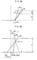
- As shown in Fig. 34, suppose that the observation point is moved from the distance D from the monitor screen to the distance D . If the positions ML, MR of the image on the monitor screen are located as they used to be, the stereoscopic image P moves rearwards in the direction of going away from the monitor screen as indicated by the intersection of the broken lines. Though this is not illustrated, if P is located in front of the monitor screen, P moves to the front side coming similarly away from the monitor screen. In other words, the longitudinal axis is extended across the monitor screen, its enlargement ratio comes to differ from that of the transverse axis. To prevent this, it is necessary to change the lengths of a and d to a and d . At this time, the relations shown by Eqs. (142), (145) must be maintained. That is to say, from Eqs. (144), (145), and (142), the values of a' and d can be obtained as:


- By Eq. (138), if e , D, S, and s are fixed, a is in proportion to d'.
- Suppose a case in which the observer moves transversely. As shown in Fig. 36, if the observer moves to right by the distance L, the stereoscopic iamge P moves to left turning about across the screen. Though not illustrated, if P is located in front of the screen, it will move to right. In order for P to be seen at the original position, ML and MR must move to ML" and MR".
- In order for the stereoscopic image P not to move, it is only necessary to move the lenses and the image-forming planes without changing the position of the intersection of the optical axes of the stereoscopic camera as shown in Fig. 37. Suppose that the two lenses move together by t in the right direction. If, at this time, the image centers 136, 137 move to 136", 137", this moving distance ts can be obtained as follows.
- By the geometric relation as shown in Fig. 37,

- Therefore,

- The moving distance ℓm of the positions of the images of p(x,y) on the image-forming planes is

- Therefore,

- The moving distance tm of the image on the
monitor screen 120 is obtained as follows. In Fig. 37, it is assumed that there is astraight line 189 dividing the distance from the image-formingplanes straight line 189 and the lines connecting the image centers 136, 137 or 136'', 137" with thecenter 138 of the monitor screen, the straight lines connecting the positions of the images on the image-forming planes with the corresponding position of the image on the monitor screen pass through theintersections 
- Substituting Eq. (150) into Eq. (153),

- From the relation shown in Fig. 38,

- Therefore, by using Eqs. (152), (153), we have:

- Suppose that the positions of the observer's eyes are moved by L in the right direction, If the position of the image under observation is denoted by P (X'',Y''),


- From Eq. (158),

- Therefore,

- From Eq. (157),

- Substituting Eq. (160) into Eq. (161),

- On the other hand, the position of the original stereoscopic image P(X,Y) is:


- From Eq. (164),


- Substituting Eq. (165) into Eq. (166),

- From Eqs. (160), (165),
- Y''=Y (168)
- Thus, it is understood that Y does not change.
- From Eqs. (163), (164),

- Using Eqs. (161), (166), and (169), the positional shift in the X-axis direction is obtained.

- Substituting Eqs. (143), (156) into Eq. (170), we have:

- Substituting Eq. (142),

- Further substituting Eq. (145),


- X is always equal to X. If, as shown above, the condition shown by Eq. (174) as well as the conditions shown by Eqs. (142), (143) is satisfied, the position of the image does not change even if the observer moves transversely. The condition of Eq. (174) can be expressed by using Eq. (145) as follows.

- To be more specific, it is necessary to set a ratio between the transverse moving distance L of the observer and the transverse moving distance t of the camera lenses so as to be equal to the enlargement ratio v of the stereoscopic image. In order for the
intersection 129 of the optical axes of the television cameras not to change regardless of the transverse movement of the camera lenses, it is needless to say necessary to move the image centers 136, 137 transversely by ℓs as indicated by Eq. (150). - If the foregoing is summarized, in order to prevent the position of the stereoscopic image P(X,Y) from moving relative to the monitor screen even if the position of the observer moves from the specified position, it is only necessary to perform the following:
- (1) When the distance between the observer and the monitor screen changes, change the focal length d of the lenses so that the change rate of a, a /a, and the change rate of d, d /d, become equal to the change rate of D, D'/D, and move the cameras in the back-and-forth (lingitudinal) direction.
- (2) When the observer moves in the transverse direction by L, move the television camera lenses transversely by the value t, obtained by dividing L by the enlargement ratio v of the stereoscopic image. In addition the positions of the image centers on the image-forming planes must be moved transversely by a/e times t. A possible method for performing the above-mentioned adjustment automatically is described in the following. Fig. 40 shows an example of the measuring method of the positional changes, D' and L, of the observer. The
observer 292 wears a helmet 194 fitted with amagnetic sensor 293. Themonitor 295 is provided with asaucer 296 for producing an artificial magnetic field. On receiving the artificial magnetic field by thesaucer 296, themagnetic sensor 293 outputs a signal in accordance with the position thereof. By this output, it is possible to detect the position of the magnetic sensor relative to thesaucer 296, and D and L can be detected by this magnetic sensor. As for means for adjusting positions a and 1 of thestereoscopic camera 297, arobot arm 298 as shown in Fig. 41 is used, but an X-Y table may be used. - Figs. 42 and 43 show an embodiment of the
stereoscopic camera 297. Twotelevision cameras side bases slide levers female screws screw rods screw rods motors sensors screw rods gears television cameras telephoto lenses lenses screw rod 285 having LH and RH threads formed on the opposite sides thereof. - Fig. 44 shows a control block diagram. A magnetic
sensor control unit 416 outputs signals representing the distance D from the observer and the screen and the transverse moving distance L relative to the center line of the monitor screen, and input into an arithmetic andcontrol unit 417. The observer's binocular space E and the enlargement ratio of the stereoscopic image are input into the arithmetic andcontrol unit 417. The arithmetric andcontrol unit 417 obtains e from signals of E and µ at anarithmetic block 419, and outputs e to acontroller 420 of the television camera space adjusting unit to set the e. Anarithmetic block 421 obtains a from signals of D, and outputs a to acontrol unit 422 for the robot. Anarithmetic block 423 obtains t from L and f, and outputs ℓ to thecontrol unit 422 for the robot. As a result, therobot 298 moves so that the position of thestereoscopic camera 297 becomes predetermined values of a and 1. Anarithmetic block 424 obtains the distance d between the optical centers of the lenses and the image-forming planes from the image-forming plane size a and the monitor screen size S, which have been predetermined. and sends the distance d to thecontrollers arithmetic block 427 obtains the movingdistance 1s of the image-forming planes from data on a , d , and 1. From the result of this as wellas the value of e , arithmetic blocks 428, 429 obtain the positions XR and XL, which data are then input intoposition controllers - As has been discussed, even if the binocular space differs among the observers, the space of the lenses of the television cameras can be adjusted, the enlargement ratio v of the stereoscopic image, and the stereoscopic image is prevented from being distorted or moved when the observer changes his position.
- According to this invention, video signals of two television cameras can be shifted in parallel, so that an accurate stereoscopic vision without distortion can be obtained. In addition, even if the observer is away from the specified position, he can get a correct stereoscopic image.
Claims (12)
Applications Claiming Priority (4)
| Application Number | Priority Date | Filing Date | Title |
|---|---|---|---|
| JP278023/89 | 1989-10-25 | ||
| JP1278023A JP2581601B2 (en) | 1989-10-25 | 1989-10-25 | 3D camera and 3D image system |
| JP225316/90 | 1990-08-29 | ||
| JP2225316A JPH04108288A (en) | 1990-08-29 | 1990-08-29 | Stereoscopic video device |
Publications (3)
| Publication Number | Publication Date |
|---|---|
| EP0425985A2 true EP0425985A2 (en) | 1991-05-08 |
| EP0425985A3 EP0425985A3 (en) | 1992-04-15 |
| EP0425985B1 EP0425985B1 (en) | 1997-06-11 |
Family
ID=26526563
Family Applications (1)
| Application Number | Title | Priority Date | Filing Date |
|---|---|---|---|
| EP90120317A Expired - Lifetime EP0425985B1 (en) | 1989-10-25 | 1990-10-23 | Stereoscopic imaging system |
Country Status (3)
| Country | Link |
|---|---|
| US (1) | US5119189A (en) |
| EP (1) | EP0425985B1 (en) |
| DE (1) | DE69030911T2 (en) |
Cited By (8)
| Publication number | Priority date | Publication date | Assignee | Title |
|---|---|---|---|---|
| FR2670349A1 (en) * | 1990-12-10 | 1992-06-12 | France Etat | DEVICE FOR THE GEOMETRIC CORRECTION OF RELIEF VIDEO IMAGES. |
| EP0817123A1 (en) * | 1996-06-27 | 1998-01-07 | Kabushiki Kaisha Toshiba | Stereoscopic display system and method |
| FR2769449A1 (en) * | 1997-09-19 | 1999-04-09 | Zeiss Carl | STEREOSCOPIC PHOTOGRAPHY AND REPRODUCTION SYSTEM |
| WO2000036845A1 (en) * | 1998-12-15 | 2000-06-22 | Street Graham S B | Apparatus and method for stereoscopic image control |
| FR2942886A1 (en) * | 2009-03-09 | 2010-09-10 | Telerelief | SIMULTANEOUS CAPTURING DEVICE OF A PLURALITY OF TAKING OF VIEWS FOR RELIEF IN RELIEF WITH CONTROLLED DEFORMATION ON A MULTISCOPIC DEVICE |
| WO2010103012A1 (en) | 2009-03-09 | 2010-09-16 | 3Dtv Solutions | System and method adapted for capturing a plurality of images for multiscopic restitution with controlled deformation |
| NL1029968C2 (en) * | 2005-03-10 | 2011-02-17 | Minoru Inaba | DIGITAL STEREO CAMERA / DIGITAL STEREO VIDEO CAMERA, 3-DIMENSIONAL DISPLAY, 3-DIMENSIONAL PROJECTOR, AND PRINTER AND STEREOVIEWER. |
| GB2572669A (en) * | 2018-01-31 | 2019-10-09 | Synaptive Medical Barbados Inc | System for three-dimensional visualization |
Families Citing this family (57)
| Publication number | Priority date | Publication date | Assignee | Title |
|---|---|---|---|---|
| WO1993022699A1 (en) * | 1992-04-24 | 1993-11-11 | Depth Enhancement Inc | Three-dimensional visualization by altered multiple two-dimensional perspective imagery |
| US5321353A (en) * | 1992-05-13 | 1994-06-14 | Storage Technolgy Corporation | System and method for precisely positioning a robotic tool |
| JP3257640B2 (en) * | 1992-06-09 | 2002-02-18 | オリンパス光学工業株式会社 | Stereoscopic endoscope device |
| JPH0795623A (en) * | 1993-06-25 | 1995-04-07 | Sanyo Electric Co Ltd | Stereo image pickup device |
| EP0641132B1 (en) * | 1993-08-26 | 1999-04-14 | Matsushita Electric Industrial Co., Ltd. | Stereoscopic image pickup apparatus |
| US5976076A (en) * | 1995-02-22 | 1999-11-02 | Kolff; Jack | Stereo laparoscope with synchronized optics |
| US5917940A (en) * | 1996-01-23 | 1999-06-29 | Nec Corporation | Three dimensional reference image segmenting method and device and object discrimination system |
| US6478730B1 (en) | 1998-09-09 | 2002-11-12 | Visionscope, Inc. | Zoom laparoscope |
| DE19905452C2 (en) * | 1999-02-09 | 2001-02-22 | Deutsch Zentr Luft & Raumfahrt | Digital stereo camera |
| US6668327B1 (en) | 1999-06-14 | 2003-12-23 | Sun Microsystems, Inc. | Distributed authentication mechanisms for handling diverse authentication systems in an enterprise computer system |
| US6767321B2 (en) | 1999-10-04 | 2004-07-27 | Robert Czarnek | Stereo laparoscope with discrete working distance |
| US6687399B1 (en) * | 2000-08-03 | 2004-02-03 | Silicon Integrated Systems Corp. | Stereo synchronizing signal generator for liquid crystal shutter glasses |
| KR100360825B1 (en) * | 2000-09-01 | 2002-11-13 | 한국해양연구원 | Single Canister Type Underwater Stereo Camera Capable of Distance Measurement |
| FI117146B (en) * | 2001-06-18 | 2006-06-30 | Karri Tapani Palovuori | Shutter function based device for projecting a stereo or multichannel image |
| US7904826B2 (en) * | 2002-03-29 | 2011-03-08 | Microsoft Corporation | Peek around user interface |
| AU2003272298A1 (en) * | 2002-09-12 | 2004-04-30 | Thomson Licensing S.A. | Personal video message system |
| US20040056948A1 (en) * | 2002-09-23 | 2004-03-25 | Gibson Robert John | Multi-play theatre |
| WO2004049734A1 (en) * | 2002-11-28 | 2004-06-10 | Seijiro Tomita | Three-dimensional image signal producing circuit and three-dimensional image display apparatus |
| JP4291862B2 (en) | 2007-07-04 | 2009-07-08 | 稔 稲葉 | 3D television system and 3D television receiver |
| USRE45394E1 (en) | 2008-10-20 | 2015-03-03 | X6D Limited | 3D glasses |
| US20110234775A1 (en) * | 2008-10-20 | 2011-09-29 | Macnaughton Boyd | DLP Link System With Multiple Projectors and Integrated Server |
| USD624952S1 (en) | 2008-10-20 | 2010-10-05 | X6D Ltd. | 3D glasses |
| USD666663S1 (en) | 2008-10-20 | 2012-09-04 | X6D Limited | 3D glasses |
| USD603445S1 (en) | 2009-03-13 | 2009-11-03 | X6D Limited | 3D glasses |
| CA2684513A1 (en) | 2008-11-17 | 2010-05-17 | X6D Limited | Improved performance 3d glasses |
| US20110205347A1 (en) * | 2008-11-17 | 2011-08-25 | X6D Limited | Universal 3d glasses for use with televisions |
| US20110216176A1 (en) * | 2008-11-17 | 2011-09-08 | Macnaughton Boyd | 3D Glasses With RF Synchronization |
| US8542326B2 (en) * | 2008-11-17 | 2013-09-24 | X6D Limited | 3D shutter glasses for use with LCD displays |
| JP4863527B2 (en) * | 2009-12-01 | 2012-01-25 | 稔 稲葉 | Stereoscopic imaging device |
| USD646451S1 (en) | 2009-03-30 | 2011-10-04 | X6D Limited | Cart for 3D glasses |
| USD672804S1 (en) | 2009-05-13 | 2012-12-18 | X6D Limited | 3D glasses |
| USD650956S1 (en) | 2009-05-13 | 2011-12-20 | X6D Limited | Cart for 3D glasses |
| JP5409107B2 (en) * | 2009-05-13 | 2014-02-05 | 任天堂株式会社 | Display control program, information processing apparatus, display control method, and information processing system |
| CA2766989A1 (en) * | 2009-07-02 | 2011-01-06 | Thomson Licensing | Method and system for differential distortion correction for three-dimensional (3d) projection |
| JP2013501414A (en) * | 2009-07-29 | 2013-01-10 | トムソン ライセンシング | Method of crosstalk correction for three-dimensional (3D) projection |
| US20110025821A1 (en) * | 2009-07-30 | 2011-02-03 | Dell Products L.P. | Multicast stereoscopic video synchronization |
| US20110063418A1 (en) * | 2009-08-04 | 2011-03-17 | Parker Matthew A | Integrated Mount and Control Device for Stereoscopic Video |
| KR101699956B1 (en) * | 2009-08-12 | 2017-01-25 | 톰슨 라이센싱 | Method and system for crosstalk and distortion corrections for three-dimensional (3d) projection |
| JP5405264B2 (en) | 2009-10-20 | 2014-02-05 | 任天堂株式会社 | Display control program, library program, information processing system, and display control method |
| JP4754031B2 (en) * | 2009-11-04 | 2011-08-24 | 任天堂株式会社 | Display control program, information processing system, and program used for stereoscopic display control |
| USD692941S1 (en) | 2009-11-16 | 2013-11-05 | X6D Limited | 3D glasses |
| USD671590S1 (en) | 2010-09-10 | 2012-11-27 | X6D Limited | 3D glasses |
| USD669522S1 (en) | 2010-08-27 | 2012-10-23 | X6D Limited | 3D glasses |
| JP2011139296A (en) * | 2009-12-28 | 2011-07-14 | Sony Corp | Video signal processing apparatus and video signal processing method |
| EP2355526A3 (en) | 2010-01-14 | 2012-10-31 | Nintendo Co., Ltd. | Computer-readable storage medium having stored therein display control program, display control apparatus, display control system, and display control method |
| USD662965S1 (en) | 2010-02-04 | 2012-07-03 | X6D Limited | 3D glasses |
| JP5540848B2 (en) * | 2010-04-08 | 2014-07-02 | ソニー株式会社 | Video signal processing device, display device, display method, and program |
| US9693039B2 (en) | 2010-05-27 | 2017-06-27 | Nintendo Co., Ltd. | Hand-held electronic device |
| USD664183S1 (en) | 2010-08-27 | 2012-07-24 | X6D Limited | 3D glasses |
| JP5709545B2 (en) * | 2011-01-18 | 2015-04-30 | キヤノン株式会社 | Imaging device |
| JP2012249137A (en) * | 2011-05-30 | 2012-12-13 | Sony Corp | Recording device, recording method, reproducing device, reproducing method, program and recording and reproducing device |
| USD711959S1 (en) | 2012-08-10 | 2014-08-26 | X6D Limited | Glasses for amblyopia treatment |
| JP6233870B2 (en) | 2012-08-28 | 2017-11-22 | 稔 稲葉 | 3D image receiver |
| TWI503618B (en) * | 2012-12-27 | 2015-10-11 | Ind Tech Res Inst | Device for acquiring depth image, calibrating method and measuring method therefore |
| CN103744256B (en) * | 2013-10-21 | 2017-03-08 | 浙江理工大学 | Realize the whirligig of 360 degree of adjustable video cameras |
| CN113775885A (en) * | 2021-09-27 | 2021-12-10 | 安徽捷呈科技文化有限公司 | Multi-azimuth image synchronous acquisition device beneficial to video production |
| TWI805174B (en) * | 2022-01-07 | 2023-06-11 | 五鈴光學股份有限公司 | Multimodal hyperspectral camera |
Family Cites Families (8)
| Publication number | Priority date | Publication date | Assignee | Title |
|---|---|---|---|---|
| US3980394A (en) * | 1973-10-16 | 1976-09-14 | Zapf Kenyon L | Stereo viewing |
| NL8005650A (en) * | 1980-10-14 | 1982-05-03 | Philips Nv | THREE-DIMENSIONAL TELEVISION IMAGE DISPLAY SYSTEM AND IMAGE RECORDING DEVICE AND IMAGE SUITABLE FOR THAT. |
| GB2147762A (en) * | 1983-10-10 | 1985-05-15 | Audim Sa | An artifical binocular vision system |
| US4677468A (en) * | 1984-08-13 | 1987-06-30 | Nec Home Electronics Ltd. | Stereoscopic television image-pickup device display device |
| GB8430980D0 (en) * | 1984-12-07 | 1985-01-16 | Robinson M | Generation of apparently three-dimensional images |
| NL8500141A (en) * | 1985-01-21 | 1986-08-18 | Delft Tech Hogeschool | METHOD FOR GENERATING A THREE-DIMENSIONAL IMPRESSION FROM A TWO-DIMENSIONAL IMAGE AT AN OBSERVER |
| JPH01246989A (en) * | 1988-03-29 | 1989-10-02 | Kanji Murakami | Three-dimensional image pickup video camera |
| US4956705A (en) * | 1989-03-10 | 1990-09-11 | Dimensional Visions Group | Electronic method and apparatus for stereoscopic photography |
-
1990
- 1990-10-23 DE DE69030911T patent/DE69030911T2/en not_active Expired - Fee Related
- 1990-10-23 EP EP90120317A patent/EP0425985B1/en not_active Expired - Lifetime
- 1990-10-24 US US07/602,864 patent/US5119189A/en not_active Expired - Fee Related
Cited By (11)
| Publication number | Priority date | Publication date | Assignee | Title |
|---|---|---|---|---|
| FR2670349A1 (en) * | 1990-12-10 | 1992-06-12 | France Etat | DEVICE FOR THE GEOMETRIC CORRECTION OF RELIEF VIDEO IMAGES. |
| EP0493993A1 (en) * | 1990-12-10 | 1992-07-08 | France Telecom | Geometric correction device for threedimsional video images |
| EP0817123A1 (en) * | 1996-06-27 | 1998-01-07 | Kabushiki Kaisha Toshiba | Stereoscopic display system and method |
| US6198484B1 (en) | 1996-06-27 | 2001-03-06 | Kabushiki Kaisha Toshiba | Stereoscopic display system |
| FR2769449A1 (en) * | 1997-09-19 | 1999-04-09 | Zeiss Carl | STEREOSCOPIC PHOTOGRAPHY AND REPRODUCTION SYSTEM |
| WO2000036845A1 (en) * | 1998-12-15 | 2000-06-22 | Street Graham S B | Apparatus and method for stereoscopic image control |
| NL1029968C2 (en) * | 2005-03-10 | 2011-02-17 | Minoru Inaba | DIGITAL STEREO CAMERA / DIGITAL STEREO VIDEO CAMERA, 3-DIMENSIONAL DISPLAY, 3-DIMENSIONAL PROJECTOR, AND PRINTER AND STEREOVIEWER. |
| FR2942886A1 (en) * | 2009-03-09 | 2010-09-10 | Telerelief | SIMULTANEOUS CAPTURING DEVICE OF A PLURALITY OF TAKING OF VIEWS FOR RELIEF IN RELIEF WITH CONTROLLED DEFORMATION ON A MULTISCOPIC DEVICE |
| WO2010103012A1 (en) | 2009-03-09 | 2010-09-16 | 3Dtv Solutions | System and method adapted for capturing a plurality of images for multiscopic restitution with controlled deformation |
| GB2572669A (en) * | 2018-01-31 | 2019-10-09 | Synaptive Medical Barbados Inc | System for three-dimensional visualization |
| GB2572669B (en) * | 2018-01-31 | 2022-11-02 | Synaptive Medical Inc | System for three-dimensional visualization |
Also Published As
| Publication number | Publication date |
|---|---|
| EP0425985A3 (en) | 1992-04-15 |
| DE69030911D1 (en) | 1997-07-17 |
| EP0425985B1 (en) | 1997-06-11 |
| DE69030911T2 (en) | 1997-11-06 |
| US5119189A (en) | 1992-06-02 |
Similar Documents
| Publication | Publication Date | Title |
|---|---|---|
| EP0425985B1 (en) | Stereoscopic imaging system | |
| US5835133A (en) | Optical system for single camera stereo video | |
| US5142357A (en) | Stereoscopic video camera with image sensors having variable effective position | |
| US5953054A (en) | Method and system for producing stereoscopic 3-dimensional images | |
| US4772944A (en) | Stereoscopic image signal processing device | |
| US5625408A (en) | Three-dimensional image recording/reconstructing method and apparatus therefor | |
| US5510832A (en) | Synthesized stereoscopic imaging system and method | |
| US5949477A (en) | Three dimensional stereoscopic television system | |
| KR0181269B1 (en) | Image Recording Method and Apparatus Using Single Image Receiver for Automatic Stereoscopic Display | |
| EP0644701A2 (en) | Image taking and/or displaying system | |
| US9509975B2 (en) | Methods for acquiring, storing, transmitting and displaying stereoscopic images | |
| EP0707287B1 (en) | Image processing apparatus and method | |
| JP2001218228A (en) | Optical system for stereoscopic image photographing and stereoscopic image photographing apparatus using the same | |
| EP0125284A1 (en) | THREE-DIMENSIONAL VIDEO APPARATUS AND METHOD USING COMPILED AND MIXED IMAGES. | |
| JPH06339155A (en) | Three-dimensional image pickup system | |
| US4994898A (en) | Color television system for processing signals from a television camera to produce a stereoscopic effect | |
| JPH07274214A (en) | Stereoscopic video camera | |
| JPH0435491A (en) | Picture quality control circuit for stereoscopic picture | |
| JPH11187425A (en) | Stereoscopic video system and method | |
| JP4617024B2 (en) | 3D video signal editing method | |
| JP2581601B2 (en) | 3D camera and 3D image system | |
| JP2001016620A (en) | Imaging device, method of determining convergence distance thereof, storage medium, and optical device | |
| JPH04108288A (en) | Stereoscopic video device | |
| JPS61177889A (en) | Stereoscopic television system | |
| JPH06169475A (en) | Three-dimensional picture showing device |
Legal Events
| Date | Code | Title | Description |
|---|---|---|---|
| PUAI | Public reference made under article 153(3) epc to a published international application that has entered the european phase |
Free format text: ORIGINAL CODE: 0009012 |
|
| 17P | Request for examination filed |
Effective date: 19901120 |
|
| AK | Designated contracting states |
Kind code of ref document: A2 Designated state(s): DE FR |
|
| PUAL | Search report despatched |
Free format text: ORIGINAL CODE: 0009013 |
|
| AK | Designated contracting states |
Kind code of ref document: A3 Designated state(s): DE FR |
|
| 17Q | First examination report despatched |
Effective date: 19940210 |
|
| GRAG | Despatch of communication of intention to grant |
Free format text: ORIGINAL CODE: EPIDOS AGRA |
|
| GRAH | Despatch of communication of intention to grant a patent |
Free format text: ORIGINAL CODE: EPIDOS IGRA |
|
| GRAH | Despatch of communication of intention to grant a patent |
Free format text: ORIGINAL CODE: EPIDOS IGRA |
|
| GRAA | (expected) grant |
Free format text: ORIGINAL CODE: 0009210 |
|
| AK | Designated contracting states |
Kind code of ref document: B1 Designated state(s): DE FR |
|
| REF | Corresponds to: |
Ref document number: 69030911 Country of ref document: DE Date of ref document: 19970717 |
|
| ET | Fr: translation filed | ||
| PLBE | No opposition filed within time limit |
Free format text: ORIGINAL CODE: 0009261 |
|
| STAA | Information on the status of an ep patent application or granted ep patent |
Free format text: STATUS: NO OPPOSITION FILED WITHIN TIME LIMIT |
|
| 26N | No opposition filed | ||
| PGFP | Annual fee paid to national office [announced via postgrant information from national office to epo] |
Ref country code: FR Payment date: 19990817 Year of fee payment: 10 |
|
| PGFP | Annual fee paid to national office [announced via postgrant information from national office to epo] |
Ref country code: DE Payment date: 19991230 Year of fee payment: 10 |
|
| PG25 | Lapsed in a contracting state [announced via postgrant information from national office to epo] |
Ref country code: FR Free format text: LAPSE BECAUSE OF NON-PAYMENT OF DUE FEES Effective date: 20010629 |
|
| PG25 | Lapsed in a contracting state [announced via postgrant information from national office to epo] |
Ref country code: DE Free format text: LAPSE BECAUSE OF NON-PAYMENT OF DUE FEES Effective date: 20010703 |
|
| REG | Reference to a national code |
Ref country code: FR Ref legal event code: ST |