EP0425248B1 - Foot pedal operated, modular sheet feeder apparatus - Google Patents
Foot pedal operated, modular sheet feeder apparatus Download PDFInfo
- Publication number
- EP0425248B1 EP0425248B1 EP90311618A EP90311618A EP0425248B1 EP 0425248 B1 EP0425248 B1 EP 0425248B1 EP 90311618 A EP90311618 A EP 90311618A EP 90311618 A EP90311618 A EP 90311618A EP 0425248 B1 EP0425248 B1 EP 0425248B1
- Authority
- EP
- European Patent Office
- Prior art keywords
- sheet
- tray
- sheets
- feed
- copy
- Prior art date
- Legal status (The legal status is an assumption and is not a legal conclusion. Google has not performed a legal analysis and makes no representation as to the accuracy of the status listed.)
- Expired - Lifetime
Links
- 238000000034 method Methods 0.000 claims description 5
- 238000012546 transfer Methods 0.000 description 10
- 108091008695 photoreceptors Proteins 0.000 description 9
- 230000036961 partial effect Effects 0.000 description 7
- 238000003825 pressing Methods 0.000 description 3
- 238000004140 cleaning Methods 0.000 description 2
- 230000005484 gravity Effects 0.000 description 2
- 239000002245 particle Substances 0.000 description 2
- 239000011347 resin Substances 0.000 description 2
- 229920005989 resin Polymers 0.000 description 2
- 238000011161 development Methods 0.000 description 1
- 230000000694 effects Effects 0.000 description 1
- 239000000835 fiber Substances 0.000 description 1
- 238000010438 heat treatment Methods 0.000 description 1
- 230000002401 inhibitory effect Effects 0.000 description 1
- 238000003780 insertion Methods 0.000 description 1
- 230000037431 insertion Effects 0.000 description 1
- 239000011810 insulating material Substances 0.000 description 1
- 239000000463 material Substances 0.000 description 1
- 239000000203 mixture Substances 0.000 description 1
- 238000012986 modification Methods 0.000 description 1
- 230000004048 modification Effects 0.000 description 1
- 230000003472 neutralizing effect Effects 0.000 description 1
- 230000003287 optical effect Effects 0.000 description 1
- 230000000284 resting effect Effects 0.000 description 1
- 230000000452 restraining effect Effects 0.000 description 1
- 230000002441 reversible effect Effects 0.000 description 1
- 238000000926 separation method Methods 0.000 description 1
- 230000035939 shock Effects 0.000 description 1
- 239000000758 substrate Substances 0.000 description 1
Images



Classifications
-
- B—PERFORMING OPERATIONS; TRANSPORTING
- B65—CONVEYING; PACKING; STORING; HANDLING THIN OR FILAMENTARY MATERIAL
- B65H—HANDLING THIN OR FILAMENTARY MATERIAL, e.g. SHEETS, WEBS, CABLES
- B65H1/00—Supports or magazines for piles from which articles are to be separated
- B65H1/02—Supports or magazines for piles from which articles are to be separated adapted to support articles on edge
- B65H1/025—Supports or magazines for piles from which articles are to be separated adapted to support articles on edge with controlled positively-acting mechanical devices for advancing the pile to present the articles to the separating device
-
- B—PERFORMING OPERATIONS; TRANSPORTING
- B65—CONVEYING; PACKING; STORING; HANDLING THIN OR FILAMENTARY MATERIAL
- B65H—HANDLING THIN OR FILAMENTARY MATERIAL, e.g. SHEETS, WEBS, CABLES
- B65H3/00—Separating articles from piles
- B65H3/02—Separating articles from piles using friction forces between articles and separator
- B65H3/06—Rollers or like rotary separators
- B65H3/0676—Rollers or like rotary separators with two or more separator rollers in the feeding direction
-
- G—PHYSICS
- G03—PHOTOGRAPHY; CINEMATOGRAPHY; ANALOGOUS TECHNIQUES USING WAVES OTHER THAN OPTICAL WAVES; ELECTROGRAPHY; HOLOGRAPHY
- G03G—ELECTROGRAPHY; ELECTROPHOTOGRAPHY; MAGNETOGRAPHY
- G03G15/00—Apparatus for electrographic processes using a charge pattern
- G03G15/50—Machine control of apparatus for electrographic processes using a charge pattern, e.g. regulating differents parts of the machine, multimode copiers, microprocessor control
- G03G15/5016—User-machine interface; Display panels; Control console
-
- G—PHYSICS
- G03—PHOTOGRAPHY; CINEMATOGRAPHY; ANALOGOUS TECHNIQUES USING WAVES OTHER THAN OPTICAL WAVES; ELECTROGRAPHY; HOLOGRAPHY
- G03G—ELECTROGRAPHY; ELECTROPHOTOGRAPHY; MAGNETOGRAPHY
- G03G15/00—Apparatus for electrographic processes using a charge pattern
- G03G15/65—Apparatus which relate to the handling of copy material
- G03G15/6588—Apparatus which relate to the handling of copy material characterised by the copy material, e.g. postcards, large copies, multi-layered materials, coloured sheet material
- G03G15/6594—Apparatus which relate to the handling of copy material characterised by the copy material, e.g. postcards, large copies, multi-layered materials, coloured sheet material characterised by the format or the thickness, e.g. endless forms
-
- G—PHYSICS
- G03—PHOTOGRAPHY; CINEMATOGRAPHY; ANALOGOUS TECHNIQUES USING WAVES OTHER THAN OPTICAL WAVES; ELECTROGRAPHY; HOLOGRAPHY
- G03G—ELECTROGRAPHY; ELECTROPHOTOGRAPHY; MAGNETOGRAPHY
- G03G2215/00—Apparatus for electrophotographic processes
- G03G2215/00362—Apparatus for electrophotographic processes relating to the copy medium handling
- G03G2215/00367—The feeding path segment where particular handling of the copy medium occurs, segments being adjacent and non-overlapping. Each segment is identified by the most downstream point in the segment, so that for instance the segment labelled "Fixing device" is referring to the path between the "Transfer device" and the "Fixing device"
- G03G2215/00379—Copy medium holder
- G03G2215/00383—Cassette
-
- G—PHYSICS
- G03—PHOTOGRAPHY; CINEMATOGRAPHY; ANALOGOUS TECHNIQUES USING WAVES OTHER THAN OPTICAL WAVES; ELECTROGRAPHY; HOLOGRAPHY
- G03G—ELECTROGRAPHY; ELECTROPHOTOGRAPHY; MAGNETOGRAPHY
- G03G2215/00—Apparatus for electrophotographic processes
- G03G2215/00362—Apparatus for electrophotographic processes relating to the copy medium handling
- G03G2215/00367—The feeding path segment where particular handling of the copy medium occurs, segments being adjacent and non-overlapping. Each segment is identified by the most downstream point in the segment, so that for instance the segment labelled "Fixing device" is referring to the path between the "Transfer device" and the "Fixing device"
- G03G2215/00396—Pick-up device
-
- G—PHYSICS
- G03—PHOTOGRAPHY; CINEMATOGRAPHY; ANALOGOUS TECHNIQUES USING WAVES OTHER THAN OPTICAL WAVES; ELECTROGRAPHY; HOLOGRAPHY
- G03G—ELECTROGRAPHY; ELECTROPHOTOGRAPHY; MAGNETOGRAPHY
- G03G2215/00—Apparatus for electrophotographic processes
- G03G2215/00362—Apparatus for electrophotographic processes relating to the copy medium handling
- G03G2215/00367—The feeding path segment where particular handling of the copy medium occurs, segments being adjacent and non-overlapping. Each segment is identified by the most downstream point in the segment, so that for instance the segment labelled "Fixing device" is referring to the path between the "Transfer device" and the "Fixing device"
- G03G2215/00405—Registration device
-
- G—PHYSICS
- G03—PHOTOGRAPHY; CINEMATOGRAPHY; ANALOGOUS TECHNIQUES USING WAVES OTHER THAN OPTICAL WAVES; ELECTROGRAPHY; HOLOGRAPHY
- G03G—ELECTROGRAPHY; ELECTROPHOTOGRAPHY; MAGNETOGRAPHY
- G03G2215/00—Apparatus for electrophotographic processes
- G03G2215/00362—Apparatus for electrophotographic processes relating to the copy medium handling
- G03G2215/00443—Copy medium
- G03G2215/00451—Paper
- G03G2215/00464—Non-standard format
- G03G2215/00468—Large sized, e.g. technical plans
Definitions
- This invention relates to a sheet feeder apparatus, and more particularly, to a sheet feeder apparatus to be used as a self-contained accessory for feeding large copy sheets to a copying machine.
- a latent electrostatic image is formed on a charge-retentive surface such as a photoconductor which generally comprises a photoconductive insulating material adhered to a conductive backing.
- This photoconductor is first provided with a uniform charge after which it is exposed to a light image of an original document to be reproduced.
- the latent electrostatic images thus formed are rendered visible by applying any one of numerous pigmented resins specifically designed for this purpose.
- the pigmented resin more commonly referred to as toner, which forms the visible images is transferred to plain paper.
- the latent electrostatic image may be generated from information electronically stored or generated, and the digital information may be converted to alphanumeric images by image generation electronics and optics.
- image generation electronics and optics form no part of the present invention.
- Paper feeders are used with automated drive rolls throughout the industry in conjunction with printers or copiers of the type just discussed in order to feed copy sheets at a high rate of speed and thereby increase the throughput of the machines. These feeders are costly, cumbersome and quite complicated when evaluated for use in feeding sheets in low cost, slow speed machines. Although it has become increasingly common to feed copy sheets in some of these machines measuring 457, 610, 914 or 1219 mm X 914 mm, use of prior sheet feeders for this application has been costly and difficult at best. One attempt in the past at feeding sheets economically is shown in the Xerox Model D, No. 4, Xerographic Flat Plate machine.
- Copy sheets are manually fed by pulling a lever in front of the machine that is connected to a ratchet controlled feed roll assembly that is resting on top of a horizontally supported stack of sheets in a feed tray.
- the ratchet mechanism will not allow the feed rolls to rotate as they are pulled over the top of sheets in the tray.
- the lever is released with the ratcheting causing the feed rolls to rotate in a reverse direction so as to not disturb the sheets remaining in the stack. This procedure is repeated for each sheet that is fed. Replenishing of the copy sheets is a major drawback to this type of feeding.
- the feed tray is positioned in a horizontal plane and has to be loaded from the outside the machine.
- US-A-4,823,963 shows a rack with two parallel trays adapted for use with a wide format photocopy machine or the like. One tray holds originals yet to be copied while the other tray holds originals already copied. The rack fits over and behind the photocopy machine so as to not require an additional workspace. This system does not address the problem of handling wide format copy sheets.
- US-A-4,053, 152 is directed to a vertical sheet feeding device which includes a means for fanning out a first portion of a stack.
- the stack is supported generally vertically and the fanning out means also includes means for restraining a second and different portion of the stack.
- the paper feed device allows air to enter between sheets of paper or the like in the stack to prevent the occurrence of double feeding. This system too is not readily adaptable to feeding "D" size sheets.
- US-A-4,026,538 describes a reciprocating sheet pusher for ejecting sheets from a substantially vertically held stack.
- the present invention is intended to overcome many of these problems with prior art devices for feeding large sheets, and accordingly provides a sheet feeder configured as a self-contained accessory to a copying machine, comprising: a sheet tray positioned to support a stack of copy sheets in a substantially vertical plane; and feed means including rotatable friction means and one-way clutch means connected to said friction means; characterised by foot pedal means connected to said feed means for moving said friction means in an upward motion such that said friction means are locked by said one-way clutch means and feed an individual copy sheet from said stack towards a ready-to-feed station of said copying machine, with continued movement of said foot pedal means causing said feed means and hence said individual copy sheet to move in a substantially vertical direction, and wherein release of said foot pedal means causes unlocking of said friction means and return of the feed means to its initial position out of contact with the sheets.
- the invention provides a low cost, foot pedal operated roll up large media feeder is disclosed that includes a media chamber mounted in a vertical plane that allows media to exit through a top portion thereof into feed rolls of a printer apparatus.
- a two position, T-shaped actuator means includes a pair of one-way clutch controlled rotating friction means mounted thereon for contacting media within the media chamber.
- a rail means slidably supports the actuator means. Replenishment of copy paper is accomplished by simply opening a door in the top of the media chamber, sliding copy paper into the chamber and closing the door.
- Figure 1 is an isometric view of a machine incorporating the features of the present invention.
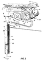
- Figure 2 is a partial side view schematic of the machine of Figure 1 showing part of the present invention.
- Figure 3A is a partial side elevational view of the paper feeder structure of Figure 2 with a feed member in its home position.
- Figure 3B is a partial side elevation of the paper feeder of Figure 3A showing the feed member of the paper feeder in its actuated position.
- Figure 4 is an enlarged partial side elevation of the paper feeder of Figure 3A depicting the paper feeding sequence of the paper feeder.
- Figure 5A is an enlarged partial isometric view of the paper feeder of Figure 3A showing the drive mechanism for the feed member in an unactuated position.
- Figure 5B is an enlarged partial isometric view of the paper feeder of Figure 3A showing the drive mechanism for the feed member in an actuated position.
- Figure 5C is an enlarged partial isometric view of the paper feeder of Figure 3A showing the drive mechanism for the feed member in an actuated position and feeding an individual sheet from a stack.
- FIG. 8 there is shown by way of example an automatic xerographic reproduction or printing machine, designated generally by the numeral 8 incorporating the idler structure of the present invention.
- Machine 8 has a suitable frame or housing 10 within which the machine xerographic section 13 is operatively supported.
- the xerographic section 13 is supported by stand 11.
- the machine xerographic section 13 includes a recording member, shown here in the form of a rotatable photoreceptor 14.
- photoreceptor 14 comprises a drum having a photoconductive surface 16.
- Other photoreceptor types such as belt, web, etc. may instead be contemplated.
- Copy sheets 17 are brought forward to transfer station 28 by idler roll 150 and registration/drive roll 160 which is controlled by sensor 152 through controller 100, with sheet guides 42, 43 serving to guide the sheet through an approximately 180° turn prior to transfer station 28. Following transfer, the sheet 17 is carried forward to a fusing section 48 where the toner image is fixed by fusing roll 49. Fusing roll 49 is heated by a suitable heater such as lamp 47 disposed within the interior of roll 49. After fixing, the copy sheet 17 is discharged into a catch tray 205 which is part of the roll up feeder 200 of the present invention.
- a transparent platen 50 supports a document as the document is moved past a scan point 52 by a constant velocity type transport 54.
- scan point 52 is in effect a scan line extending across the width of platen 50 at a desired point along platen 50 where the document is scanned line by line as the document is moved along platen 50 by transport 54.
- Transport 54 has input and output document feed roll pairs 55, 56, respectively, on each side of scan point 52 for moving a document across platen 50 at a predetermined speed.
- Exposure lamp 58 is provided to illuminate a strip-like area of platen 50 at scan point 52. The image rays from the document line scanned are transmitted by a gradient index fiber lens array 60 to exposure station 22 to expose the photoconductive surface 16 of the moving photoreceptor 14.
- Developing station 24 includes a developer housing 65, the lower part of which forms a sump 66 for holding a quantity of developer within canister 67.
- developer comprises a mixture of larger carrier particles and smaller toner or ink particles.
- a rotatable magnetic brush developer roll 68 is disposed in predetermined operative relation to the photoconductive surface 16 in developer housing 65, roll 68 serving to bring developer from sump 66 into developing relation with photoreceptor 14 to develop the latent electrostatic images formed on the photoconductive surface 16. All of the machine functions are controlled by conventional controller or microprocessor 100.
- Roll-up paper feeder 200 includes copy sheets 17 that are supported in stack-like fashion substantially vertical on a horizontal base portion 202 of copy sheet supply tray 201. An angle of approximately 13 degrees from a vertical plane would be an acceptable positioning of tray 201.
- a T-shaped actuator means 220 with feed means in the form of hollow, cylindrical rolls 224 and 225 is manipulated against the topmost copy sheet 17 of the stack of sheets in order to feed the topmost copy sheet into the nip of the registration roll pair which registers the copy sheets with the image on the photoconductive surface 16 of photoreceptor 14.
- Registration roll pair 150, 160 advance the copy sheet to transfer station 28.
- transfer/detack means such as transfer/detack corotrons 29, 30 bring the copy sheet into transfer relation with the developed image on photoconductive surface 16 and separate the copy sheet therefrom for fixing and discharge as a finished copy.
- the top surface of roll-up feeder 200 serves as a copy sheet support and bypass guide in order to allow an operator to feed copy sheets into the machine separate from the feeder unit.
- Paper feeder 200 comprises a copy sheet supply tray 201 that could be heated, if desired, with copy sheets 17 positioned therein and supported in stack-like fashion on base 202. Heating of the tray maintains dryness of the sheets as well as prevents curl from setting up in the sheets.
- a T-shaped, two-position actuator means 220 is positioned adjacent to and removed from the copy sheets and has a support member 221 slidably positioned within a channel of slide member 218 for movement up and down within the slide.
- the actuator means 220 includes feed means 224 and 225 on opposite extremities and is controlled by a leaf spring mechanism 219 such that when foot pedal 238 is in a first position, ( Figure 3A) the actuator means is removed from the the sheet stack and when foot pedal 238 is in a second position ( Figure 3B), the actuator means is loaded in a first direction against the first copy sheet 17 in the stack of sheets into operative relationship with one-way clutch 216 ( Figure 3A) controlled feed means or feed rolls 224 and 225. During this movement of the actuator means, leaf spring 219 is acting against the movement.
- Feed rolls 224 and 225 are mounted on an articulated shaft in order to prevent skewing of the media during the feeding process and are manipulated by continued pressing on foot pedal 238 to be moved in a second and upward direction away from the the bottom of the tray in order to feed the topmost copy sheet to a point where it is captured by the nip of the idler/registration roll pair 150, 160 which registers the copy sheet with the image on the photoconductive surface 16 of the photoreceptor.
- Registration roll 160 advances each copy sheet to transfer station 28 by way of metering roll 212.
- Metering roll 212 is rotated by friction between it and a copy sheet and serves to alert the operator that a sheet has been feed and when it stops rotating, the operator knows that it is time to prepare to feed another sheet.
- Copy sheet tray 201 has an attachment 203 connected to its outer surface that is used to store original documents as copying of a particular document is taking place or for later copying or for storing documents that have already been copied.
- the documents to be copied are stored face or printed side forward or toward the outer wall of the tray 201 while documents that have already been copied are guided by baffle 211 into tray 201 and stored facing away from the outer surface of the tray.
- Attachment 203 also has a separate catch tray compartment 205 for catching copy sheets as they exit the machine.
- baffle means 217 The lead edges of copy sheets are guided by baffle means 217 into contact with a support surface means 206 of the catch tray with continued transport of the copy sheets by the machine causing a trail edge portion of each copy sheet to flip away from the machine and over an angled top portion 207 of the catch tray. This is useful because as each job is finished, the operator will grasp the collated documents document storage attachment 203 with one hand and the copy sheets in compartment 205 with the other prior to leaving the machine.
- Support member 206 is adjustable in order to accommodate different sizes of copy sheets.
- Pulley drive mechanism 230 for the actuator member as shown in Figures 5A - 5C includes a block 231 and tackle 232 in the form of a wire that is used in conjunction with a series of wheels 233 through 237 with wire 232 being connected to the actuator member at shaft 214 ( Figure 4).
- a wire 239 connects foot pedal 238 to block 231 of the drive mechanism.
- Copy sheets within tray 201 are taught lightly and held upright opposite roll 225 by a pad 244 on an orthogonal member 243 which extends from baffle 242 that is supported through movable linkage 241 which is supported by support 240 that is attached to a wall of tray 201.
- Identical structure supports the copy sheets opposite roll 224 as well.
- a curved baffle 213 that extends upright opposite the inside wall of tray 201 corrugates the stack and thereby increases the beam strength of the sheets in the stack.
- Baffle 242 is moved back toward support 240 for loading of new copy sheets into tray 201. It can be clearly seen in Figure 3A that baffle 242 is in an unactuated position for copy sheet loading purposes and in Figure 3B has been actuated and extended to a position just opposite the stack of sheets 17. Springs 222 are used to control the movement of baffles 242.
- foot pedal 238 is in its home position and rolls 224 and 225 are removed from the stack, while in Figure 5B, movement is shown in the pulley system and the rolls are moved into contact with the stack.
- a sheet is being fed in Figure 5C due to continued downward movement of foot pedal 238.
- a document is inserted into machine 8 in the direction of arrow A .
- the document advances to a point and stops for the insertion of a copy sheet.
- An operator then steps on foot pedal 238 which is connected to actuator 220 and feed rolls 224 and 225 via pulley system 230.
- the actuator is moved from its home position placing the feed rolls onto the copy sheets as pressing of the foot pedal is continued.
- the shock applied to the top sheet in the stack provides inertial sheet separation and because the copy sheets are placed in the tray vertically, in this case approximately 90°, gravity retards the remaining sheets.
- Copy sheet movement sensor or metering roll 212 is included to indicate to the operator that 1.) a sheet has been fed from the storage tray and 2.) to indicate when the copy sheet has left the copier so that the operator can feed another document and subsequently press the foot pedal and feed another copy sheet.
- the paper feeder includes a foot pedal, a T-shaped actuator with feed means as a part thereof and a pulley system connecting the foot pedal to the actuator.
- the feed tray has a bottom surface that supports copy sheets at an angle of about 90° with respect to a horizontal plane in order to make use of gravity in inhibiting multifeeding.
Landscapes
- Engineering & Computer Science (AREA)
- Physics & Mathematics (AREA)
- General Physics & Mathematics (AREA)
- Mechanical Engineering (AREA)
- Microelectronics & Electronic Packaging (AREA)
- Sheets, Magazines, And Separation Thereof (AREA)
- Paper Feeding For Electrophotography (AREA)
Description
- This invention relates to a sheet feeder apparatus, and more particularly, to a sheet feeder apparatus to be used as a self-contained accessory for feeding large copy sheets to a copying machine.
- In the art of xerography or other similar image reproducing arts, a latent electrostatic image is formed on a charge-retentive surface such as a photoconductor which generally comprises a photoconductive insulating material adhered to a conductive backing. This photoconductor is first provided with a uniform charge after which it is exposed to a light image of an original document to be reproduced. The latent electrostatic images thus formed are rendered visible by applying any one of numerous pigmented resins specifically designed for this purpose. In the case of a reusable photoconductive surface, the pigmented resin, more commonly referred to as toner, which forms the visible images is transferred to plain paper.
- It should be understood that for the purpose of the present invention, the latent electrostatic image may be generated from information electronically stored or generated, and the digital information may be converted to alphanumeric images by image generation electronics and optics. However, such image generation electronic and optical devices form no part of the present invention.
- Paper feeders are used with automated drive rolls throughout the industry in conjunction with printers or copiers of the type just discussed in order to feed copy sheets at a high rate of speed and thereby increase the throughput of the machines. These feeders are costly, cumbersome and quite complicated when evaluated for use in feeding sheets in low cost, slow speed machines. Although it has become increasingly common to feed copy sheets in some of these machines measuring 457, 610, 914 or 1219 mm X 914 mm, use of prior sheet feeders for this application has been costly and difficult at best. One attempt in the past at feeding sheets economically is shown in the Xerox Model D, No. 4, Xerographic Flat Plate machine. Copy sheets are manually fed by pulling a lever in front of the machine that is connected to a ratchet controlled feed roll assembly that is resting on top of a horizontally supported stack of sheets in a feed tray. The ratchet mechanism will not allow the feed rolls to rotate as they are pulled over the top of sheets in the tray. Once a sheet is pulled forward by use of the lever and feed rolls, the lever is released with the ratcheting causing the feed rolls to rotate in a reverse direction so as to not disturb the sheets remaining in the stack. This procedure is repeated for each sheet that is fed. Replenishing of the copy sheets is a major drawback to this type of feeding. The feed tray is positioned in a horizontal plane and has to be loaded from the outside the machine. First, the tray has to be removed from the machine, then the top of the tray opened. Next, the feed roll assembly is lifted up and rotated toward the back of the tray. Paper can then be added to the tray. As one can appreciate, this loading procedure would be especially cumbersome and difficult when handling "D" size sheets measuring 610 X 914 mm. US-A-4,823,963 shows a rack with two parallel trays adapted for use with a wide format photocopy machine or the like. One tray holds originals yet to be copied while the other tray holds originals already copied. The rack fits over and behind the photocopy machine so as to not require an additional workspace. This system does not address the problem of handling wide format copy sheets. US-A-4,053, 152 is directed to a vertical sheet feeding device which includes a means for fanning out a first portion of a stack. The stack is supported generally vertically and the fanning out means also includes means for restraining a second and different portion of the stack. The paper feed device allows air to enter between sheets of paper or the like in the stack to prevent the occurrence of double feeding. This system too is not readily adaptable to feeding "D" size sheets. US-A-4,026,538 describes a reciprocating sheet pusher for ejecting sheets from a substantially vertically held stack.
- The present invention is intended to overcome many of these problems with prior art devices for feeding large sheets, and accordingly provides a sheet feeder configured as a self-contained accessory to a copying machine, comprising: a sheet tray positioned to support a stack of copy sheets in a substantially vertical plane; and feed means including rotatable friction means and one-way clutch means connected to said friction means; characterised by foot pedal means connected to said feed means for moving said friction means in an upward motion such that said friction means are locked by said one-way clutch means and feed an individual copy sheet from said stack towards a ready-to-feed station of said copying machine, with continued movement of said foot pedal means causing said feed means and hence said individual copy sheet to move in a substantially vertical direction, and wherein release of said foot pedal means causes unlocking of said friction means and return of the feed means to its initial position out of contact with the sheets.
- In a preferred form, the invention provides a low cost, foot pedal operated roll up large media feeder is disclosed that includes a media chamber mounted in a vertical plane that allows media to exit through a top portion thereof into feed rolls of a printer apparatus. A two position, T-shaped actuator means includes a pair of one-way clutch controlled rotating friction means mounted thereon for contacting media within the media chamber. A rail means slidably supports the actuator means. Replenishment of copy paper is accomplished by simply opening a door in the top of the media chamber, sliding copy paper into the chamber and closing the door.
- A sheet feeder in accordance with the invention will now be described, by way of example, with reference to the accompanying drawings, in which:-
- Figure 1 is an isometric view of a machine incorporating the features of the present invention.
- Figure 2 is a partial side view schematic of the machine of Figure 1 showing part of the present invention.
- Figure 3A is a partial side elevational view of the paper feeder structure of Figure 2 with a feed member in its home position.
- Figure 3B is a partial side elevation of the paper feeder of Figure 3A showing the feed member of the paper feeder in its actuated position.
- Figure 4 is an enlarged partial side elevation of the paper feeder of Figure 3A depicting the paper feeding sequence of the paper feeder.
- Figure 5A is an enlarged partial isometric view of the paper feeder of Figure 3A showing the drive mechanism for the feed member in an unactuated position.
- Figure 5B is an enlarged partial isometric view of the paper feeder of Figure 3A showing the drive mechanism for the feed member in an actuated position.
- Figure 5C is an enlarged partial isometric view of the paper feeder of Figure 3A showing the drive mechanism for the feed member in an actuated position and feeding an individual sheet from a stack.
- Referring to Figures 1 and 2 of the drawings there is shown by way of example an automatic xerographic reproduction or printing machine, designated generally by the numeral 8 incorporating the idler structure of the present invention.
- Machine 8 has a suitable frame or
housing 10 within which the machinexerographic section 13 is operatively supported. Thexerographic section 13 is supported bystand 11. Briefly, and as will be familiar to those skilled in the art, the machinexerographic section 13 includes a recording member, shown here in the form of arotatable photoreceptor 14. In the exemplary arrangement shown,photoreceptor 14 comprises a drum having aphotoconductive surface 16. Other photoreceptor types such as belt, web, etc. may instead be contemplated. Operatively disposed about the periphery ofphotoreceptor 14 arecharge station 18 withcharge corotron 19 for placing a uniform charge on thephotoconductive surface 16 ofphotoreceptor 14, exposure station 22 where the previously chargedphotoconductive surface 16 is exposed to image rays of the document being copied or reproduced,development station 24 where the latent electrostatic image created onphotoconductive surface 16 is developed by toner,transfer station 28 withtransfer corotrons copy sheet 17 brought forward in timed relation with the developed image onphotoconductive surface 16, andcleaning station 34 that could include a cleaning blade anddischarge corotron 36 for removing leftover developer fromphotoconductive surface 16 and neutralizing residual charges thereon. -
Copy sheets 17 are brought forward totransfer station 28 byidler roll 150 and registration/drive roll 160 which is controlled bysensor 152 throughcontroller 100, withsheet guides transfer station 28. Following transfer, thesheet 17 is carried forward to afusing section 48 where the toner image is fixed byfusing roll 49.Fusing roll 49 is heated by a suitable heater such aslamp 47 disposed within the interior ofroll 49. After fixing, thecopy sheet 17 is discharged into acatch tray 205 which is part of the roll upfeeder 200 of the present invention. - A
transparent platen 50 supports a document as the document is moved past a scan point 52 by a constantvelocity type transport 54. As will be understood, scan point 52 is in effect a scan line extending across the width ofplaten 50 at a desired point alongplaten 50 where the document is scanned line by line as the document is moved alongplaten 50 bytransport 54.Transport 54 has input and output documentfeed roll pairs platen 50 at a predetermined speed.Exposure lamp 58 is provided to illuminate a strip-like area ofplaten 50 at scan point 52. The image rays from the document line scanned are transmitted by a gradient index fiber lens array 60 to exposure station 22 to expose thephotoconductive surface 16 of the movingphotoreceptor 14. - Developing
station 24 includes adeveloper housing 65, the lower part of which forms asump 66 for holding a quantity of developer withincanister 67. As will be understood by those skilled in the art, developer comprises a mixture of larger carrier particles and smaller toner or ink particles. A rotatable magneticbrush developer roll 68 is disposed in predetermined operative relation to thephotoconductive surface 16 indeveloper housing 65,roll 68 serving to bring developer fromsump 66 into developing relation withphotoreceptor 14 to develop the latent electrostatic images formed on thephotoconductive surface 16. All of the machine functions are controlled by conventional controller ormicroprocessor 100. - Roll-up
paper feeder 200 includescopy sheets 17 that are supported in stack-like fashion substantially vertical on ahorizontal base portion 202 of copysheet supply tray 201. An angle of approximately 13 degrees from a vertical plane would be an acceptable positioning oftray 201. A T-shaped actuator means 220 with feed means in the form of hollow,cylindrical rolls topmost copy sheet 17 of the stack of sheets in order to feed the topmost copy sheet into the nip of the registration roll pair which registers the copy sheets with the image on thephotoconductive surface 16 ofphotoreceptor 14.Registration roll pair station 28. There, suitable transfer/detack means such as transfer/detack corotrons 29, 30 bring the copy sheet into transfer relation with the developed image onphotoconductive surface 16 and separate the copy sheet therefrom for fixing and discharge as a finished copy. The top surface of roll-upfeeder 200 serves as a copy sheet support and bypass guide in order to allow an operator to feed copy sheets into the machine separate from the feeder unit. - As shown in Figures 2 - 5C,
Paper feeder 200 comprises a copysheet supply tray 201 that could be heated, if desired, withcopy sheets 17 positioned therein and supported in stack-like fashion onbase 202. Heating of the tray maintains dryness of the sheets as well as prevents curl from setting up in the sheets. A T-shaped, two-position actuator means 220 is positioned adjacent to and removed from the copy sheets and has asupport member 221 slidably positioned within a channel ofslide member 218 for movement up and down within the slide. The actuator means 220 includes feed means 224 and 225 on opposite extremities and is controlled by aleaf spring mechanism 219 such that whenfoot pedal 238 is in a first position, (Figure 3A) the actuator means is removed from the the sheet stack and whenfoot pedal 238 is in a second position (Figure 3B), the actuator means is loaded in a first direction against thefirst copy sheet 17 in the stack of sheets into operative relationship with one-way clutch 216 (Figure 3A) controlled feed means or feed rolls 224 and 225. During this movement of the actuator means,leaf spring 219 is acting against the movement. Feed rolls 224 and 225 are mounted on an articulated shaft in order to prevent skewing of the media during the feeding process and are manipulated by continued pressing onfoot pedal 238 to be moved in a second and upward direction away from the the bottom of the tray in order to feed the topmost copy sheet to a point where it is captured by the nip of the idler/registration roll pair photoconductive surface 16 of the photoreceptor.Registration roll 160 advances each copy sheet to transferstation 28 by way ofmetering roll 212.Metering roll 212 is rotated by friction between it and a copy sheet and serves to alert the operator that a sheet has been feed and when it stops rotating, the operator knows that it is time to prepare to feed another sheet. Return offoot pedal 238 to its first or rest position causes the actuator means to slide in a third direction downward withinchannel 218 with one-way clutch 216 allowing the feed rolls to roll against the sheet stack and thereby not disturb the remaining sheets in the. stack. Movement of the actuator in this downward direction will also causeleaf spring mechanism 219 to take over control of the actuator member and cause it to be moved thereby away from the the stack and not make frictional contact with the top or first sheet of the sheets remaining in the stack during return of the foot pedal to its first position. The foot pedal can be manipulated to present a fresh copy sheet to the registration roll as use requires. It should be understood that a motor could replace the foot pedal and friction pads could replace the rolls, if desired. - With reference to Figures 3A and 3B,
Copy sheet tray 201 has anattachment 203 connected to its outer surface that is used to store original documents as copying of a particular document is taking place or for later copying or for storing documents that have already been copied. The documents to be copied are stored face or printed side forward or toward the outer wall of thetray 201 while documents that have already been copied are guided bybaffle 211 intotray 201 and stored facing away from the outer surface of the tray.Attachment 203 also has a separatecatch tray compartment 205 for catching copy sheets as they exit the machine. The lead edges of copy sheets are guided by baffle means 217 into contact with a support surface means 206 of the catch tray with continued transport of the copy sheets by the machine causing a trail edge portion of each copy sheet to flip away from the machine and over an angledtop portion 207 of the catch tray. This is useful because as each job is finished, the operator will grasp the collated documents documentstorage attachment 203 with one hand and the copy sheets incompartment 205 with the other prior to leaving the machine.Support member 206 is adjustable in order to accommodate different sizes of copy sheets. -
Pulley drive mechanism 230 for the actuator member as shown in Figures 5A - 5C includes ablock 231 and tackle 232 in the form of a wire that is used in conjunction with a series ofwheels 233 through 237 withwire 232 being connected to the actuator member at shaft 214 (Figure 4). Awire 239 connectsfoot pedal 238 to block 231 of the drive mechanism. Copy sheets withintray 201 are taught lightly and held uprightopposite roll 225 by apad 244 on anorthogonal member 243 which extends frombaffle 242 that is supported throughmovable linkage 241 which is supported bysupport 240 that is attached to a wall oftray 201. Identical structure supports the copy sheets oppositeroll 224 as well. Acurved baffle 213 that extends upright opposite the inside wall oftray 201 corrugates the stack and thereby increases the beam strength of the sheets in the stack.Baffle 242 is moved back towardsupport 240 for loading of new copy sheets intotray 201. It can be clearly seen in Figure 3A that baffle 242 is in an unactuated position for copy sheet loading purposes and in Figure 3B has been actuated and extended to a position just opposite the stack ofsheets 17.Springs 222 are used to control the movement ofbaffles 242. In Figure 5A,foot pedal 238 is in its home position and rolls 224 and 225 are removed from the stack, while in Figure 5B, movement is shown in the pulley system and the rolls are moved into contact with the stack. A sheet is being fed in Figure 5C due to continued downward movement offoot pedal 238. - In operation, a document is inserted into machine 8 in the direction of arrow A. The document advances to a point and stops for the insertion of a copy sheet. An operator then steps on
foot pedal 238 which is connected to actuator 220 and feed rolls 224 and 225 viapulley system 230. The actuator is moved from its home position placing the feed rolls onto the copy sheets as pressing of the foot pedal is continued. When the actuator is forced onto the copy sheets by the foot pedal, the shock applied to the top sheet in the stack provides inertial sheet separation and because the copy sheets are placed in the tray vertically, in this case approximately 90°, gravity retards the remaining sheets. Subsequent continued pressing of the foot pedal causes upward movement of the now locked feed rolls of the actuator with the friction between the feed rolls and the first sheet in the stack causing the copy sheet to move about 100 - 150 mm out of the tray pastmetering roll 212 and into the registration rolls of the machine as shown by arrow B. The microprocessor starts the document and copy sheet in synchronism with each other with the document traveling in the direction of arrow A and the copy sheet traveling in the direction of arrow B as shown in Figures 1 and 2. This process is repeated as necessary for the number of copies required. Copy sheet movement sensor ormetering roll 212 is included to indicate to the operator that 1.) a sheet has been fed from the storage tray and 2.) to indicate when the copy sheet has left the copier so that the operator can feed another document and subsequently press the foot pedal and feed another copy sheet. - It should now be understood that a cost effective roll-up device for the feeding of sheets from a feed tray to a copier has been disclosed that is simple, low cost, and foot operated or electrically driven. The paper feeder includes a foot pedal, a T-shaped actuator with feed means as a part thereof and a pulley system connecting the foot pedal to the actuator. The feed tray has a bottom surface that supports copy sheets at an angle of about 90° with respect to a horizontal plane in order to make use of gravity in inhibiting multifeeding.
- While the invention has been described with reference to the structure shown, it is not confined to the specific details set forth, but is intended to cover such modifications or changes as may come within the scope of the following claims.
Claims (9)
- A sheet feeder configured as a self-contained accessory to a copying machine, comprising: a sheet tray (201) positioned to support a stack of copy sheets (17) in a substantially vertical plane; and feed means (220) including rotatable friction means (224, 225) and one-way clutch means (216) connected to said friction means; characterised by foot pedal means (238) connected (239, 232, 221) to said feed means (220) for moving said friction means (224, 225) in an upward motion such that said friction means are locked by said one-way clutch means and feed an individual copy sheet from said stack towards a ready-to-feed station (150, 160) of said copying machine, with continued movement of said foot pedal means causing said feed means and hence said individual copy sheet to move in a substantially vertical direction, and wherein release of said foot pedal means causes unlocking of said friction means and return of the feed means to its initial position out of contact with the sheets.
- The sheet feeder of claim 1, wherein said friction means (224, 225) comprises cylindrical rubber rolls
- The sheet feeder of claim 2, wherein said rolls (224, 225) are mounted on an articulated shaft in order to prevent skewing of said sheets during the feeding process.
- The sheet feeder of any one of claims 1 to 3, wherein said sheet tray (201) is heated.
- The sheet feeder of any one of claims 1 to 4, including a motion wheel (212) that is actuated by movement of a sheet in order to indicate movement of the sheet past the motion wheel.
- The sheet feeder of any one of claims 1 to 5, including corrugation means associated with said sheet tray to impart vertical corrugation to the sheets in order to lend rigidity to said vertically standing sheets.
- The sheet feeder of any one of claims 1 to 6, wherein said sheet tray includes an attachment to an outside surface thereof that has a first compartment for stacking prefed original documents facing said copier apparatus and the restacking of post fed original documents facing away from said copier apparatus and a second compartment that is positioned to catch sheets exiting said copier apparatus.
- The sheet feeder of claim 7, wherein said second compartment that is positioned to catch sheets exiting said copier apparatus is configured such that a portion of each sheet automatically bends over a wall of said second compartment away from said copier apparatus.
- The sheet feeder of any one of claims 1 to 6 including a document holding tray (203) connected to an outer surface of said copy sheet tray (201) for holding original documents before they are fed to the copier and after they have been fed to the copier, and a catch tray (205) connected to an outer surface of said document holding tray, said catch tray (205) having adjustable means (206) thereon that changes the space within said catch tray (205) available to copy sheets output by the copying machine in order to accommodate a wide variety of copy sheet sizes.
Applications Claiming Priority (2)
| Application Number | Priority Date | Filing Date | Title |
|---|---|---|---|
| US07/425,789 US5040777A (en) | 1989-10-23 | 1989-10-23 | Foot pedal operated, modular, roll up paper feeder apparatus |
| US425789 | 2003-04-29 |
Publications (3)
| Publication Number | Publication Date |
|---|---|
| EP0425248A2 EP0425248A2 (en) | 1991-05-02 |
| EP0425248A3 EP0425248A3 (en) | 1991-11-21 |
| EP0425248B1 true EP0425248B1 (en) | 1994-09-14 |
Family
ID=23688052
Family Applications (1)
| Application Number | Title | Priority Date | Filing Date |
|---|---|---|---|
| EP90311618A Expired - Lifetime EP0425248B1 (en) | 1989-10-23 | 1990-10-23 | Foot pedal operated, modular sheet feeder apparatus |
Country Status (4)
| Country | Link |
|---|---|
| US (1) | US5040777A (en) |
| EP (1) | EP0425248B1 (en) |
| JP (1) | JPH03166135A (en) |
| DE (1) | DE69012504T2 (en) |
Families Citing this family (22)
| Publication number | Priority date | Publication date | Assignee | Title |
|---|---|---|---|---|
| US5188352A (en) * | 1992-04-01 | 1993-02-23 | Xerox Corporation | Copy output stacker for engineering size copies |
| US5207417A (en) * | 1992-04-01 | 1993-05-04 | Xerox Corporation | Active copy sheet catch and stacking device |
| US5361124A (en) * | 1992-05-26 | 1994-11-01 | Xerox Corporation | Temperature control system for a fuser |
| US5257567A (en) * | 1992-05-26 | 1993-11-02 | Xerox Corporation | Sheet cutting apparatus |
| US5223902A (en) * | 1992-05-26 | 1993-06-29 | Xerox Corporation | Heat and pressure fuser incorporating a moisture collection and removal system |
| US5190167A (en) * | 1992-05-26 | 1993-03-02 | Xerox Corporation | Engineering size document stacker |
| US5190279A (en) * | 1992-05-26 | 1993-03-02 | Xerox Corporation | Copy output stacker for engineering size copies |
| US5212529A (en) * | 1992-05-26 | 1993-05-18 | Xerox Corporation | Heat and pressure fuser |
| US5237378A (en) * | 1992-05-26 | 1993-08-17 | Xerox Corporation | Copier/printer employing a roll media feed apparatus and dual functions sensors |
| US5392710A (en) * | 1993-06-15 | 1995-02-28 | Li; Raymond | Modular feeder printing system |
| US5386282A (en) * | 1993-11-15 | 1995-01-31 | Xerox Corporation | Blade controller assembly with modified cam |
| US5396313A (en) * | 1994-03-23 | 1995-03-07 | Xerox Corporation | Out of media detection system for a roll media feed apparatus |
| JPH08227190A (en) * | 1994-11-25 | 1996-09-03 | Xerox Corp | Document copying machine |
| US5996991A (en) * | 1996-11-28 | 1999-12-07 | Agfa-Gevaert | Thermal printer with sheet pressure means |
| DE69616569T2 (en) * | 1996-11-28 | 2002-06-27 | Agfa-Gevaert N.V., Mortsel | Stack of thermosensitive sheets |
| US5913628A (en) * | 1998-06-29 | 1999-06-22 | Sides, Ii; William R. | Preformed paper catching tray for electronic printers and other devices |
| US5924808A (en) * | 1998-06-29 | 1999-07-20 | Sides, Ii; William R. | Paper catching tray for electronic printers and other devices |
| US6375318B1 (en) * | 1999-09-21 | 2002-04-23 | Hewlett-Packard Company | Heated media input tray for an imaging device |
| CN102390749B (en) * | 2011-07-18 | 2014-02-05 | 深圳市天腾实业有限公司 | Paper ticket machine |
| US9376277B2 (en) | 2013-11-18 | 2016-06-28 | Xerox Corporation | Foot-activated media supply devices |
| JP6708584B2 (en) * | 2017-05-12 | 2020-06-10 | キヤノン株式会社 | Sheet storage device and printing device |
| US10674024B1 (en) * | 2019-06-27 | 2020-06-02 | Kyocera Document Solutions Inc. | Scanning apparatus and system with assists to enable nonmanual situating and scanning of documents |
Family Cites Families (5)
| Publication number | Priority date | Publication date | Assignee | Title |
|---|---|---|---|---|
| US3866901A (en) * | 1973-10-01 | 1975-02-18 | Xerox Corp | Reverse buckle feeder |
| JPS5411671Y2 (en) * | 1975-10-16 | 1979-05-24 | ||
| US4026538A (en) * | 1976-04-12 | 1977-05-31 | Pitney-Bowes, Inc. | Sheet pusher |
| US4157822A (en) * | 1977-12-27 | 1979-06-12 | International Business Machines Corporation | Document feeder with recirculation and unloading |
| US4823963A (en) * | 1988-03-11 | 1989-04-25 | Ozalid Corp. | Tray for organizing originals in a photocopy machine |
-
1989
- 1989-10-23 US US07/425,789 patent/US5040777A/en not_active Expired - Fee Related
-
1990
- 1990-10-17 JP JP2280558A patent/JPH03166135A/en active Pending
- 1990-10-23 EP EP90311618A patent/EP0425248B1/en not_active Expired - Lifetime
- 1990-10-23 DE DE69012504T patent/DE69012504T2/en not_active Expired - Fee Related
Also Published As
| Publication number | Publication date |
|---|---|
| EP0425248A2 (en) | 1991-05-02 |
| EP0425248A3 (en) | 1991-11-21 |
| US5040777A (en) | 1991-08-20 |
| JPH03166135A (en) | 1991-07-18 |
| DE69012504T2 (en) | 1995-04-06 |
| DE69012504D1 (en) | 1994-10-20 |
Similar Documents
| Publication | Publication Date | Title |
|---|---|---|
| US5040777A (en) | Foot pedal operated, modular, roll up paper feeder apparatus | |
| US5285249A (en) | Finishing apparatus for stapling sheets stacked first-to-last or last-to-first | |
| US4436406A (en) | Paper feeder for recording apparatus | |
| CA1138006A (en) | Dual mode catch tray | |
| US3709595A (en) | Printer system | |
| US5137174A (en) | Pivoting paper tray | |
| US4996556A (en) | Large document copying system | |
| US5085419A (en) | Paper feeder insert tray | |
| US4303235A (en) | Paper cassette | |
| JP2883647B2 (en) | Sheet stack supporting device and sheet feeding device | |
| EP0363077B1 (en) | Sheet feeders | |
| CA1119237A (en) | Apparatus for producing double-sided copies | |
| EP0407152A2 (en) | Sheet stackers | |
| GB2205276A (en) | Duplex printing in electrophotographic apparatus | |
| US5364216A (en) | Apparatus for applying a binding strip to document sets | |
| US4088403A (en) | Replenishable photosensitive system | |
| JP3327575B2 (en) | Electrophotographic printing machine, paper feeder and paper feed input / output device | |
| JPH05265277A (en) | Duplex feeder | |
| US5052674A (en) | Paper feeder apparatus | |
| US5270563A (en) | Method and mechanism for sensing copy sheet weight | |
| EP0103386A2 (en) | Sheet feeder with retractable gate | |
| US5248138A (en) | Sheet supply tray | |
| JPH0326832B2 (en) | ||
| JPS6151168A (en) | Electrostatic recorder | |
| US3658321A (en) | Magazine for photoconductive elements |
Legal Events
| Date | Code | Title | Description |
|---|---|---|---|
| PUAI | Public reference made under article 153(3) epc to a published international application that has entered the european phase |
Free format text: ORIGINAL CODE: 0009012 |
|
| AK | Designated contracting states |
Kind code of ref document: A2 Designated state(s): DE FR GB |
|
| PUAL | Search report despatched |
Free format text: ORIGINAL CODE: 0009013 |
|
| AK | Designated contracting states |
Kind code of ref document: A3 Designated state(s): DE FR GB |
|
| 17P | Request for examination filed |
Effective date: 19920429 |
|
| 17Q | First examination report despatched |
Effective date: 19930329 |
|
| GRAA | (expected) grant |
Free format text: ORIGINAL CODE: 0009210 |
|
| AK | Designated contracting states |
Kind code of ref document: B1 Designated state(s): DE FR GB |
|
| REF | Corresponds to: |
Ref document number: 69012504 Country of ref document: DE Date of ref document: 19941020 |
|
| ET | Fr: translation filed | ||
| PLBE | No opposition filed within time limit |
Free format text: ORIGINAL CODE: 0009261 |
|
| STAA | Information on the status of an ep patent application or granted ep patent |
Free format text: STATUS: NO OPPOSITION FILED WITHIN TIME LIMIT |
|
| 26N | No opposition filed | ||
| PGFP | Annual fee paid to national office [announced via postgrant information from national office to epo] |
Ref country code: FR Payment date: 19981009 Year of fee payment: 9 |
|
| PGFP | Annual fee paid to national office [announced via postgrant information from national office to epo] |
Ref country code: GB Payment date: 19981023 Year of fee payment: 9 |
|
| PGFP | Annual fee paid to national office [announced via postgrant information from national office to epo] |
Ref country code: DE Payment date: 19981103 Year of fee payment: 9 |
|
| PG25 | Lapsed in a contracting state [announced via postgrant information from national office to epo] |
Ref country code: GB Free format text: LAPSE BECAUSE OF NON-PAYMENT OF DUE FEES Effective date: 19991023 |
|
| GBPC | Gb: european patent ceased through non-payment of renewal fee |
Effective date: 19991023 |
|
| PG25 | Lapsed in a contracting state [announced via postgrant information from national office to epo] |
Ref country code: FR Free format text: LAPSE BECAUSE OF NON-PAYMENT OF DUE FEES Effective date: 20000630 |
|
| PG25 | Lapsed in a contracting state [announced via postgrant information from national office to epo] |
Ref country code: DE Free format text: LAPSE BECAUSE OF NON-PAYMENT OF DUE FEES Effective date: 20000801 |
|
| REG | Reference to a national code |
Ref country code: FR Ref legal event code: ST |