EP0425158A1 - Starter motor for an internal combustion engine - Google Patents
Starter motor for an internal combustion engine Download PDFInfo
- Publication number
- EP0425158A1 EP0425158A1 EP90311288A EP90311288A EP0425158A1 EP 0425158 A1 EP0425158 A1 EP 0425158A1 EP 90311288 A EP90311288 A EP 90311288A EP 90311288 A EP90311288 A EP 90311288A EP 0425158 A1 EP0425158 A1 EP 0425158A1
- Authority
- EP
- European Patent Office
- Prior art keywords
- assembly
- abutments
- resilient element
- solenoid
- starter motor
- Prior art date
- Legal status (The legal status is an assumption and is not a legal conclusion. Google has not performed a legal analysis and makes no representation as to the accuracy of the status listed.)
- Withdrawn
Links
Images


Classifications
-
- F—MECHANICAL ENGINEERING; LIGHTING; HEATING; WEAPONS; BLASTING
- F02—COMBUSTION ENGINES; HOT-GAS OR COMBUSTION-PRODUCT ENGINE PLANTS
- F02N—STARTING OF COMBUSTION ENGINES; STARTING AIDS FOR SUCH ENGINES, NOT OTHERWISE PROVIDED FOR
- F02N15/00—Other power-operated starting apparatus; Component parts, details, or accessories, not provided for in, or of interest apart from groups F02N5/00 - F02N13/00
- F02N15/02—Gearing between starting-engines and started engines; Engagement or disengagement thereof
- F02N15/04—Gearing between starting-engines and started engines; Engagement or disengagement thereof the gearing including disengaging toothed gears
- F02N15/06—Gearing between starting-engines and started engines; Engagement or disengagement thereof the gearing including disengaging toothed gears the toothed gears being moved by axial displacement
- F02N15/067—Gearing between starting-engines and started engines; Engagement or disengagement thereof the gearing including disengaging toothed gears the toothed gears being moved by axial displacement the starter comprising an electro-magnetically actuated lever
Definitions
- This invention relates to a starter motor for an internal combustion engine, and to a lever assembly for transmitting movement from the solenoid to the pinion assembly of such a starter motor.
- a "pre-engaged" starter motor the axially moveable pinion assembly of the starter motor is moved along its driving shaft from a rest position to a position in which the pinion gear wheel of the assembly can mesh with the ring gear of the engine to be started, by movement of the axially movable armature of a solenoid.
- the solenoid armature is coupled to the pinion assembly by a lever arrangement and within the coupling between the solenoid armature and the pinion assembly it is necessary to provide for "lost-motion" so that in the event that the pinion gear wheel meets the engine ring gear in tooth-to-tooth abutment, the solenoid armature can still move to close the starter motor energizing switch contacts even though the pinion assembly is held against further movement. It has previously been proposed to provide the "lost-motion" by flexure of the lever arrangement which couples the solenoid armature to the pinion assembly.
- French Patent Specification 1424804 shows, in Figure 5, an arrangement wherein the solenoid armature is coupled to the starter motor pinion assembly by means of a composite lever, that it to say a lever incorporating more than one element.
- the lever of Figure 5 of French Specification 1424804 has its individual elements secured together by means of a rivet at their midpoint. Such an construction is inherently disadvantageous since the operation of producing a hole, and introducing a rivet, inevitability weakens the lever construction and produces a region at which the lever may fracture in use. Nevertheless the concept shown in Figure 5 of French Specification 1424804 is interesting since it would be possible, by judicious construction of the individual elements of the lever, to permit a pre-loading to be built into the lever during its construction.
- a starter motor for use with an internal combustion engine, comprising an electric motor, an axially movable pinion assembly rotatable by said motor, a solenoid spaced from the pinion assembly axis and including an armature moveable from a rest position towards an operative position by energization of an electromagnet winding of the solenoid, and, a lever assembly mounted for pivotal movement about an axis passing between the axes of said solenoid and said pinion assembly, said lever assembly linking the armature of said solenoid and said pinion assembly such that movement of the armature is transmitted to the pinion assembly to move the pinion assembly axially from a rest position towards an operative position, said lever assembly comprising a rigid element supported for pivotal movement about said axis, and a resilient element carried by said rigid element and coupled at one end to said armature, the end of the lever assembly remote from said solenoid cooperating with said pinion assembly for moving said pinion assembly axially,
- said third abutment is defined by a transversely extending pin whereby the lever assembly is mounted for pivotal movement about said axis.
- the position of at least one of said first and second abutments in relation to the position of the other abutments is adjustable.
- the end of the lever assembly remote from said solenoid cooperates with said pinion assembly by way of the other end of said resilient element.
- the rigid element is a sheet metal pressing.
- the starter motor is, with the exception of the lever assembly, of a generally conventional form comprising a housing 11 containing a d.c., permanent magnet field, electric motor 12, the rotor shaft 13 of which carries a pinion assembly 14.
- the pinion assembly 14 comprises a pinion gear wheel 15 which is mounted on the shaft 13 for both rotational and axial movement relative to the shaft 13, and a unidirectional roller clutch 16 the input member of which is axially moveable on the shaft 13 by way of a splined connection.
- the pinion gear wheel 15 is coupled to the output member of the clutch 16 and thus rotation of the shaft 13 in one direction is transmitted to the pinion gear wheel 15 by the clutch 16.
- the pinion assembly 14 is moveable axially on the shaft 13 from a rest position (as shown in Figure 1) to an operative position in which, in use, the pinion gear wheel 15 meshes with the ring gear of an engine to be started.
- a solenoid 17 is provided for moving the pinion assembly 14 from its rest position to its operative position, the solenoid 17 including an axially moveable armature 18 and a fixed electromagnet winding 19 which, when energized, causes retraction of the armature 18 against the action of a return spring 21.
- the axis of the solenoid 17 is parallel to and spaced from the axis of the shaft 13, the solenoid 17 being secured to the housing 11.
- a lever assembly 22 is coupled at one end to the armature 18 and coupled at its opposite end to the pinion assembly 14. Intermediate its ends the lever assembly 22 is pivotally mounted on the housing 11 for pivotal movement about an axis passing between, and lying at right angles to, the axes of the solenoid 17 and the shaft 13.
- the lever assembly 22 comprises a rigid element 23, a resilient element 24, and a pivot pin 25.
- the rigid element 23 is formed as a pressing from mild steel sheet and is generally in the form of an inverted Y.
- the element 23 includes a planar leg portion 23 a having upstanding parallel sidewalls 27 such that the leg portion 23 a is of channel-shaped cross-section.
- the sidewalls 27 are continued as a pair of oppositely curved limbs 23 b terminating in parallel regions 28 the marginal edges of which are turned inwardly such that the regions 28 are of channel-shaped cross-section.
- the regions 28 are each closed at their free end by an upturned tag 28 a .
- the sidewalls 27 Adjacent the junction of the limbs 23 b and the sidewalls 27 the sidewalls 27 are drilled to receive the pivot pin 25 which is in the form of a length or steel bar of circular cross-section.
- the spacing between the regions 28 of the limbs 23 b is such that the limbs 28 can be positioned on opposite sides respectively of the input member of the roller clutch 16 of the pinion assembly 14.
- the resilient element 24 of the lever assembly is formed from a planar piece of spring steel or similar resilient material and comprises a leg portion 24 a having a longitudinally extending integral tongue 29 at one end and a pair of integral divergent limbs 31 at its opposite end. The free ends of the limbs 31 terminate in inturned portions 32.
- the resilient element 24 is introduced into the rigid element 23 such that the free end regions of the limbs 31 are received within the channel-section portions 28 and the leg portion 24 is received between the upstanding sidewalls 27.
- the tongue 29 seats against the upstanding abutment 26.
- the projecting tongue 28 of the lever assembly is engaged in a stirrup projecting from the end of the armature 18, the laterally projecting ends of the pivot pin 25 are received in appropriate recesses of the housing 11, and the inwardly projecting portions 32 of the element 24 are received between appropriately positioned pairs of abutments on the roller clutch input member of the pinion gear wheel assembly 14.
- the solenoid 17 is energized the magnetic field generated by the energized winding 19 causes retraction of the armature 18, and provided that the pinion gear wheel 15 of the pinion assembly 14 can make meshing engagement with the ring gear of the engine then the lever assembly 22 acts as a rigid lever to transmit movement of the armature 18 to the pinion assembly 14 to move the pinion assembly 14 to its operative position.
- Full retraction of the armature 18 causes closure of an electrical switch which in turn controls energization of the electric motor 12.
- the motor 12 is energized to rotate the pinion gear wheel 15, and with it the ring gear of the engine to be started.
- axial movement of the pinion assembly 14 is prevented at a point before the armature 18 will have been fully retracted.
- the armature 18 continues to retract thereby flexing the element 24 of the lever in a direction to move the tongue 29 away from the abutment 26.
- the pre-stressing of the resilient element 24 of the lever provides an initial pre-loading of the element in relation to the flexure which is caused in the tooth-to-tooth abutment condition.
- the pre-stressing of the element 24 permits a lower rate spring to be employed in the construction of the lever assembly 22 thereby affording greater control over the axial loading applied to the pinion in the tooth-to-tooth abutment condition, optimisation of solenoid electromagnet winding size, and avoiding an increase in overall starter motor length, as compared with a lever assembly design which does not embody pre-stressing, it being understood that in a lever design without pre-stressing then a much higher rate resilient element would be needed in order to ensure that no deflection of the resilient element occurs during normal operation of the starter motor.
- the lever assembly 22 acts as a rigid lever in the event that there is no tooth-to-tooth abutment and thus when used in, for example, a starter motor for a high powered diesel engine, where pinion "pumping" can be a problem, the axial reciprocation of the pinion is limited in one direction by an end stop on the pinion shaft and in the other direction by the lever assembly.
- the reciprocation does not include "float” arising from flexure in the lever assembly 22 as could arise if the resilient element 24 of the lever assembly were not pre-stressed.
- Figures 7 to 10 illustrate modification in which the pinion assembly of the starter motor is carried on an axially moveable lay-shaft rather than upon the rotor shaft of the electric motor.
- the starter motor includes a housing 11 containing an electric motor 12 the output shaft 13 of which drives a pinion assembly 14 through a reduction gearing 31.
- the reduction gearing 31 includes a gear wheel 32 on the shaft 13 and gear teeth 33 formed in the exterior of the large diameter outer member of the roller clutch 16.
- the pinion gear wheel 15 of the pinion assembly 14 is carried by an axially moveable lay-shaft 34 moveable from a rest position (as shown in Figure 7) to an operative position in which the pinion gear wheel 15 meshes with the engine ring gear, by operation of a solenoid 17.
- the structural arrangement of the solenoid 17 differs from the solenoid illustrated in Figure 1, although the differences are not of significance to the present invention.
- the solenoid 17 still includes an armature 18 which is retracted upon energization of an electromagnet winding 19 and a lever assembly 42 pivotally supported by the housing 11 intermediate the axes of the solenoid 17 and the shaft 34, transmits movement of the armature 18 to the shaft 34.
- the lever assembly 42 bears against an end of the lay-shaft 34, and thus there is no necessity for one end of the lever assembly to be bifurcated as is the case in the arrangement of Figure 1.
- the lever assembly 42 comprises a rigid element 43, a resilient element 44 and a pivot pin 45.
- the rigid element 44 is a pressing or stamping formed from mild steel sheet and comprises a planar base 43 a having integral, parallel, upstanding sidewalls 47 such that the element 43 is of channel-shaped cross-section throughout its length. At one end the channel is closed by an upturned end wall 48 a and at its opposite end the channel is partially closed by a pair of inturned tags 49 formed at the ends of the sidewalls 47.
- the base 43 a is formed with a circular aperture 51.
- the base 43 a is cut to define first and second integral tangs 52, 53 which are bent upwardly to project into the channel section of the element 43.
- the resilient element 44 is a strip of spring steel having an integral, longitudinally extending tongue 44 a at one end thereof.
- the element 44 is introduced into the element 43 so as to rest on the free ends of the tangs 52, 53.
- One end of the element 44 is adjacent the end wall 48 a of the element 43 and the tongue 44 a at the opposite end of the element 44 projects from the element 43 between the inturned tags 49.
- the element 44 partially obstructs the apertures destined to receive the pivot pin 45, and thus before the pivot pin 45 can be introduced the element 44 must be flexed, between the tangs 52, 53, to depress the element 44 towards the base 43 a . Thereafter the pivot pin 45 can be introduced and will retain the element 44 in the pre-stressed condition.
- one, or both of the abutments constituted by the tangs 52, 53 can be bent to adjust the pre-stressing of the element 44.
- the projecting tongue 44 a of the element 44 engages in a stirrup of the armature 18, the projecting ends of the pivot pin 45 are received in corresponding recesses of the housing 11 to pivotally mount the lever, and a bearing member provided at one end of the lay-shaft 34 extends through the aperture 51 to abut the end of the element 44 remote from the tongue 44 a during retraction of the armature 18.
- the pre-stressing of the element 44 ensures that the element 44 acts as a rigid lever in transmitting the movement of the armature 18 to the shaft 34 and thus the pinion assembly 14.
- the element 44 flexes so permitting the armature 18 to continue to move even though the pinion assembly has been arrested.
- the restoration of the resilient element 44 drives the shaft 34 and thus the pinion gear wheel 15 to its operative position.
- both the lever assembly 22 and the lever assembly 42 can be pre-assembled provided that the projecting ends of the pivot pin 25 or 45 can be appropriately received by the housing 11. It would of course be possible to construct the lever assemblies in situ although it is preferable to pre-assemble them. Moreover, adjustment of the pre-stressing of the resilient elements of the levers is again preferably preformed prior to introduction of the lever assembly into the starter motor, but can, if desired, be performed by appropriate bending of the abutment 26 or one or more of the tangs 52, 53 in situ.
- Figure 1 and Figure 7 appear to show the resilient elements of the lever assemblies as a two layer configuration. The intention in each view is to show the median plane of each resilient element, but it is to be understood that if desired each resilient element could comprise a pair of resilient strips in facial contact.
- the rigid elements 23, 43 of the lever assemblies could be moulded in a synthetic resin material, for example a glass filled nylon material but it will be understood that there must be other provision for adjustment of the resilient element pre-load since the resilient element abutments would not be bendable as is the case with a metal element 23 or 43.
- the elements 24, 44 could be formed from a suitable synthetic resin material.
- the invention resides not only in a starter motor utilising such lever assembles, but also in the lever assembles themselves.
Landscapes
- Engineering & Computer Science (AREA)
- Chemical & Material Sciences (AREA)
- Combustion & Propulsion (AREA)
- Mechanical Engineering (AREA)
- General Engineering & Computer Science (AREA)
- Connection Of Motors, Electrical Generators, Mechanical Devices, And The Like (AREA)
Abstract
A starter motor, for use with an internal combustion engine, comprising an electric motor (12), an axially movable pinion assembly (14) rotatable by said motor (12), a solenoid (17) spaced from the pinion assembly axis for moving the pinion assembly (14) and, a lever assembly (22) mounted for pivotal movement about an axis passing between the axes of the solenoid (17) and the pinion assembly (14), said lever assembly (22) linking the armature (18) of said solenoid (17) and said pinion assembly (14), said lever assembly (22) comprising a rigid element (23) supported for pivotal movement about said axis by means of a transversely extending pivot pin (25), and a resilient element (24) carried by said rigid element (23) and coupled at one end to said armature (18), and, said rigid element (23) including first and second abutments (26, 28) disposed on opposite sides respectively of said pivot axis and abutting one face of said resilient element (24), the resilient element extending between said abutments and said pivot pin (25) and the relationship of said pivot pin and said abutments providing a predetermined pre-stressing of said resilient element (24).
Description
- This invention relates to a starter motor for an internal combustion engine, and to a lever assembly for transmitting movement from the solenoid to the pinion assembly of such a starter motor.
- In a "pre-engaged" starter motor the axially moveable pinion assembly of the starter motor is moved along its driving shaft from a rest position to a position in which the pinion gear wheel of the assembly can mesh with the ring gear of the engine to be started, by movement of the axially movable armature of a solenoid. The solenoid armature is coupled to the pinion assembly by a lever arrangement and within the coupling between the solenoid armature and the pinion assembly it is necessary to provide for "lost-motion" so that in the event that the pinion gear wheel meets the engine ring gear in tooth-to-tooth abutment, the solenoid armature can still move to close the starter motor energizing switch contacts even though the pinion assembly is held against further movement. It has previously been proposed to provide the "lost-motion" by flexure of the lever arrangement which couples the solenoid armature to the pinion assembly. French Patent Specification 1424804 shows, in Figure 5, an arrangement wherein the solenoid armature is coupled to the starter motor pinion assembly by means of a composite lever, that it to say a lever incorporating more than one element.
- The lever of Figure 5 of French Specification 1424804 has its individual elements secured together by means of a rivet at their midpoint. Such an construction is inherently disadvantageous since the operation of producing a hole, and introducing a rivet, inevitability weakens the lever construction and produces a region at which the lever may fracture in use. Nevertheless the concept shown in Figure 5 of French Specification 1424804 is interesting since it would be possible, by judicious construction of the individual elements of the lever, to permit a pre-loading to be built into the lever during its construction. Unfortunately the degree of pre-loading which could be built into a lever of the kind shown in Figure 5 of French Specification 1424804 is quite small, and thus there is a risk that during use of the lever the flexing element thereof may be flexed beyond its yield point, and thus may take an undesirable permanent set. It is an object of the present invention to provide a starter motor, and a lever assembly for use in a starter motor, wherein a resiliently flexible element of the lever assembly can be given an adequate pre-stress in a simple and convenient manner avoiding the disadvantages of the prior art, including the disadvantages of the arrangement disclosed in French Specification 1424804.
- In accordance with the present invention there is provided a starter motor, for use with an internal combustion engine, comprising an electric motor, an axially movable pinion assembly rotatable by said motor, a solenoid spaced from the pinion assembly axis and including an armature moveable from a rest position towards an operative position by energization of an electromagnet winding of the solenoid, and, a lever assembly mounted for pivotal movement about an axis passing between the axes of said solenoid and said pinion assembly, said lever assembly linking the armature of said solenoid and said pinion assembly such that movement of the armature is transmitted to the pinion assembly to move the pinion assembly axially from a rest position towards an operative position, said lever assembly comprising a rigid element supported for pivotal movement about said axis, and a resilient element carried by said rigid element and coupled at one end to said armature, the end of the lever assembly remote from said solenoid cooperating with said pinion assembly for moving said pinion assembly axially, and, said rigid element including first and second abutments disposed on opposite sides respectively of said pivot axis and abutting one face of said resilient element, and a third abutment between said first and second abutments and engaging the opposite face of said resilient element, the resilient element extending between said abutments and the relationship of said abutments providing a predetermined pre-stressing of said resilient element.
- Preferably said third abutment is defined by a transversely extending pin whereby the lever assembly is mounted for pivotal movement about said axis.
- Preferably the position of at least one of said first and second abutments in relation to the position of the other abutments is adjustable.
- Desirably the end of the lever assembly remote from said solenoid cooperates with said pinion assembly by way of the other end of said resilient element.
- Desirably the rigid element is a sheet metal pressing.
- Examples of the present invention are illustrated in the accompanying drawings wherein,
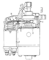
- Figure 1 is a side elevational view, partly in section, of a starter motor in accordance with a first example of the present invention,
- Figure 2 is a front elevational view of the lever assembly of the starter motor of Figure 1,
- Figure 3 is a sectional view on the line A - A in Figure 2,
- Figure 4 is a front elevational view of the resilient element of the lever assembly of Figure 2,
- Figures 5 and 6 are scrap views illustrating adjustment of the pre-stressing of the resilient element of the lever assembly shown in Figure 2,
- Figure 7 is a sectional view of part of a starter motor in accordance with a second example of the present invention, and
- Figures 8, 9 and 10 are views similar to Figures 2, 3 and 4 respectively but of the lever assembly of the starter motor of Figure 7.
- Referring first to Figures 1 to 6 of the accompanying drawings the starter motor is, with the exception of the lever assembly, of a generally conventional form comprising a
housing 11 containing a d.c., permanent magnet field,electric motor 12, therotor shaft 13 of which carries apinion assembly 14. Thepinion assembly 14 comprises apinion gear wheel 15 which is mounted on theshaft 13 for both rotational and axial movement relative to theshaft 13, and aunidirectional roller clutch 16 the input member of which is axially moveable on theshaft 13 by way of a splined connection. Thepinion gear wheel 15 is coupled to the output member of theclutch 16 and thus rotation of theshaft 13 in one direction is transmitted to thepinion gear wheel 15 by theclutch 16. - The
pinion assembly 14 is moveable axially on theshaft 13 from a rest position (as shown in Figure 1) to an operative position in which, in use, thepinion gear wheel 15 meshes with the ring gear of an engine to be started. Asolenoid 17 is provided for moving thepinion assembly 14 from its rest position to its operative position, thesolenoid 17 including an axiallymoveable armature 18 and a fixed electromagnet winding 19 which, when energized, causes retraction of thearmature 18 against the action of areturn spring 21. The axis of thesolenoid 17 is parallel to and spaced from the axis of theshaft 13, thesolenoid 17 being secured to thehousing 11. - A
lever assembly 22 is coupled at one end to thearmature 18 and coupled at its opposite end to thepinion assembly 14. Intermediate its ends thelever assembly 22 is pivotally mounted on thehousing 11 for pivotal movement about an axis passing between, and lying at right angles to, the axes of thesolenoid 17 and theshaft 13. - The
lever assembly 22 comprises arigid element 23, aresilient element 24, and apivot pin 25. - The
rigid element 23 is formed as a pressing from mild steel sheet and is generally in the form of an inverted Y. Thus theelement 23 includes a planar leg portion 23a having upstandingparallel sidewalls 27 such that the leg portion 23a is of channel-shaped cross-section. At one end the planar region of the leg portion 23a projects beyond thesidewalls 27 and is turned upwardly to define anabutment 26. At the opposite end of the planar region of the leg portion 23a, thesidewalls 27 are continued as a pair of oppositelycurved limbs 23b terminating inparallel regions 28 the marginal edges of which are turned inwardly such that theregions 28 are of channel-shaped cross-section. Theregions 28 are each closed at their free end by an upturned tag 28a. - Adjacent the junction of the
limbs 23b and thesidewalls 27 thesidewalls 27 are drilled to receive thepivot pin 25 which is in the form of a length or steel bar of circular cross-section. The spacing between theregions 28 of thelimbs 23b is such that thelimbs 28 can be positioned on opposite sides respectively of the input member of theroller clutch 16 of thepinion assembly 14. - The
resilient element 24 of the lever assembly is formed from a planar piece of spring steel or similar resilient material and comprises a leg portion 24a having a longitudinally extendingintegral tongue 29 at one end and a pair of integraldivergent limbs 31 at its opposite end. The free ends of thelimbs 31 terminate in inturnedportions 32. During construction of thelever assembly 22 theresilient element 24 is introduced into therigid element 23 such that the free end regions of thelimbs 31 are received within the channel-section portions 28 and theleg portion 24 is received between theupstanding sidewalls 27. Thetongue 29 seats against theupstanding abutment 26. Pressure is then applied to the leg portion 24a of theelement 24 to flex theelement 24 towards the base of the leg portion 23a of therigid element 23, thus deflecting theelement 24 beyond the apertures in thesidewalls 27 and permitting introduction of thepivot pin 25 through the apertures. It will be recognised that during stressing of theelement 24 in this manner theelement 24 flexes over substantially the whole of its length since it is being flexed between theabutment 26 and theregions 28 of therigid element 23. After introduction of thepivot pin 25 theelement 24 is retained in the stressed condition by abutment of the central region of theelement 24 with thepin 25. Figures 5 and 6 illustrate that the angular positioning of theabutment 26 in relation to the remainder of therigid element 23 can be varied, by bending theabutment 26 relative to the remainder of theelement 23, to adjust the pre-stressing of theelement 24. - In use the projecting
tongue 28 of the lever assembly is engaged in a stirrup projecting from the end of thearmature 18, the laterally projecting ends of thepivot pin 25 are received in appropriate recesses of thehousing 11, and the inwardly projectingportions 32 of theelement 24 are received between appropriately positioned pairs of abutments on the roller clutch input member of the piniongear wheel assembly 14. When thesolenoid 17 is energized the magnetic field generated by the energized winding 19 causes retraction of thearmature 18, and provided that thepinion gear wheel 15 of thepinion assembly 14 can make meshing engagement with the ring gear of the engine then thelever assembly 22 acts as a rigid lever to transmit movement of thearmature 18 to thepinion assembly 14 to move thepinion assembly 14 to its operative position. - Full retraction of the
armature 18 causes closure of an electrical switch which in turn controls energization of theelectric motor 12. Thus upon full retraction of thearmature 18 themotor 12 is energized to rotate thepinion gear wheel 15, and with it the ring gear of the engine to be started. In the event that thepinion gear wheel 15 meets the engine ring gear in a tooth-to-tooth abutment condition then axial movement of thepinion assembly 14 is prevented at a point before thearmature 18 will have been fully retracted. However, thearmature 18 continues to retract thereby flexing theelement 24 of the lever in a direction to move thetongue 29 away from theabutment 26. Thus the further movement of thearmature 18 takes place against the combined action of thereturn spring 21 and the resilience of thelever element 24. When thearmature 18 reaches its fully retracted position it closes the aforementioned switch so energizing themotor 12 and thus rotating thepinion gear wheel 15. Initial rotation of thegear wheel 15 disrupts the tooth-to-tooth abutment condition so that the pinion gear wheel can be rapidly driven axially into meshing engagement with the engine ring gear by the resilient restoring action of thelever element 24. - It will be recognised that the pre-stressing of the
resilient element 24 of the lever provides an initial pre-loading of the element in relation to the flexure which is caused in the tooth-to-tooth abutment condition. The pre-stressing of theelement 24 permits a lower rate spring to be employed in the construction of thelever assembly 22 thereby affording greater control over the axial loading applied to the pinion in the tooth-to-tooth abutment condition, optimisation of solenoid electromagnet winding size, and avoiding an increase in overall starter motor length, as compared with a lever assembly design which does not embody pre-stressing, it being understood that in a lever design without pre-stressing then a much higher rate resilient element would be needed in order to ensure that no deflection of the resilient element occurs during normal operation of the starter motor. - As mentioned above, the
lever assembly 22 acts as a rigid lever in the event that there is no tooth-to-tooth abutment and thus when used in, for example, a starter motor for a high powered diesel engine, where pinion "pumping" can be a problem, the axial reciprocation of the pinion is limited in one direction by an end stop on the pinion shaft and in the other direction by the lever assembly. The reciprocation does not include "float" arising from flexure in thelever assembly 22 as could arise if theresilient element 24 of the lever assembly were not pre-stressed. - Figures 7 to 10 illustrate modification in which the pinion assembly of the starter motor is carried on an axially moveable lay-shaft rather than upon the rotor shaft of the electric motor. Thus the starter motor includes a
housing 11 containing anelectric motor 12 theoutput shaft 13 of which drives apinion assembly 14 through areduction gearing 31. Thereduction gearing 31 includes agear wheel 32 on theshaft 13 andgear teeth 33 formed in the exterior of the large diameter outer member of theroller clutch 16. Thepinion gear wheel 15 of thepinion assembly 14 is carried by an axially moveable lay-shaft 34 moveable from a rest position (as shown in Figure 7) to an operative position in which thepinion gear wheel 15 meshes with the engine ring gear, by operation of asolenoid 17. The structural arrangement of thesolenoid 17 differs from the solenoid illustrated in Figure 1, although the differences are not of significance to the present invention. Thesolenoid 17 still includes anarmature 18 which is retracted upon energization of an electromagnet winding 19 and alever assembly 42 pivotally supported by thehousing 11 intermediate the axes of thesolenoid 17 and theshaft 34, transmits movement of thearmature 18 to theshaft 34. - The
lever assembly 42 bears against an end of the lay-shaft 34, and thus there is no necessity for one end of the lever assembly to be bifurcated as is the case in the arrangement of Figure 1. Thus thelever assembly 42 comprises arigid element 43, aresilient element 44 and apivot pin 45. Therigid element 44 is a pressing or stamping formed from mild steel sheet and comprises a planar base 43a having integral, parallel,upstanding sidewalls 47 such that theelement 43 is of channel-shaped cross-section throughout its length. At one end the channel is closed by an upturned end wall 48a and at its opposite end the channel is partially closed by a pair ofinturned tags 49 formed at the ends of thesidewalls 47. Intermediate their ends thesidewalls 47 are drilled to provide apertures for receiving thepivot pin 45 and adjacent the upturned end wall 48 the base 43a is formed with acircular aperture 51. At each side of the midpoint thereof the base 43a is cut to define first and secondintegral tangs element 43. - The
resilient element 44 is a strip of spring steel having an integral, longitudinally extending tongue 44a at one end thereof. During construction of thelever assembly 42 theelement 44 is introduced into theelement 43 so as to rest on the free ends of thetangs element 44 is adjacent the end wall 48a of theelement 43 and the tongue 44a at the opposite end of theelement 44 projects from theelement 43 between the inturned tags 49. In this configuration theelement 44 partially obstructs the apertures destined to receive thepivot pin 45, and thus before thepivot pin 45 can be introduced theelement 44 must be flexed, between thetangs element 44 towards the base 43a. Thereafter thepivot pin 45 can be introduced and will retain theelement 44 in the pre-stressed condition. - As described above in relation to the
abutment 26 one, or both of the abutments constituted by thetangs element 44. During use of thelever assembly 42 the projecting tongue 44a of theelement 44 engages in a stirrup of thearmature 18, the projecting ends of thepivot pin 45 are received in corresponding recesses of thehousing 11 to pivotally mount the lever, and a bearing member provided at one end of the lay-shaft 34 extends through theaperture 51 to abut the end of theelement 44 remote from the tongue 44a during retraction of thearmature 18. As described above, provided that thepinion gear wheel 15 can freely mesh with the ring gear of the engine to be started then the pre-stressing of theelement 44 ensures that theelement 44 acts as a rigid lever in transmitting the movement of thearmature 18 to theshaft 34 and thus thepinion assembly 14. However, in the event of a tooth-to-tooth abutment between thepinion gear wheel 15 and the engine ring gear then theelement 44 flexes so permitting thearmature 18 to continue to move even though the pinion assembly has been arrested. After energization of the motor, and disruption of the tooth-to-tooth abutment condition, the restoration of theresilient element 44 drives theshaft 34 and thus thepinion gear wheel 15 to its operative position. The advantages of pre-stressing of thelever element 44 are as discussed above. - It will be recognised that both the
lever assembly 22 and thelever assembly 42 can be pre-assembled provided that the projecting ends of thepivot pin housing 11. It would of course be possible to construct the lever assemblies in situ although it is preferable to pre-assemble them. Moreover, adjustment of the pre-stressing of the resilient elements of the levers is again preferably preformed prior to introduction of the lever assembly into the starter motor, but can, if desired, be performed by appropriate bending of theabutment 26 or one or more of thetangs - Figure 1 and Figure 7 appear to show the resilient elements of the lever assemblies as a two layer configuration. The intention in each view is to show the median plane of each resilient element, but it is to be understood that if desired each resilient element could comprise a pair of resilient strips in facial contact.
- The
rigid elements metal element elements - It is to be recognised that the invention resides not only in a starter motor utilising such lever assembles, but also in the lever assembles themselves.
Claims (7)
1 A starter motor, for use with an internal combustion engine, comprising an electric motor (12), an axially movable pinion assembly (14) rotatable by said motor, a solenoid (17) spaced from the pinion assembly axis and including an armature (18) moveable from a rest position towards an operative position by energization of an electromagnet winding (19) of the solenoid, and, a lever assembly (22) mounted for pivotal movement about an axis passing between the axes of said solenoid and said pinion assembly, said lever assembly linking the armature of said solenoid and said pinion assembly such that movement of the armature is transmitted to the pinion assembly to move the pinion assembly axially from a rest position towards an operative position, the starter motor being characterized in that said lever assembly (22) comprises a rigid element (23; 43) supported for pivotal movement about said axis, and a resilient element (24; 44) carried by said rigid element and coupled at one end to said armature, the end of the lever assembly remote from said solenoid cooperating with said pinion assembly for moving said pinion assembly axially, and, said rigid element (23; 43) including first and second abutments (26, 28; 52, 53) disposed on opposite sides respectively of said pivot axis and abutting one face of said resilient element (24; 44), and a third abutment (25; 45) between said first and second abutments and engaging the opposite face of said resilient element, the resilient element extending between said abutments and the relationship of said abutments providing a predetermined pre-stressing of said resilient element.
2 A starter motor as claimed in Claim 1 wherein said third abutment is defined by a transversely extending pin (25; 45) whereby the lever assembly is mounted for pivotal movement about said axis.
3 A starter motor as claimed in Claim 1 or Claim 2 wherein the position of at least one (26; 52) of said first and second abutments in relation to the position of the other abutments is adjustable.
4 A starter motor as claimed in any one of Claims 1 to 3 wherein the end of the lever assembly remote from said solenoid cooperates with said pinion assembly by way of the other end of said resilient element.
5 A starter motor as claimed in any one of Claims 1 to 4 wherein the rigid element is a sheet metal pressing.
6 A lever assembly for use in a starter motor as claimed in any one of Claims 1 to 5 comprising a rigid element (23; 43) to be supported for pivotal movement about an axis and a resilient element (24; 44) carried by said rigid element, said rigid element including first and second abutments (26, 28; 52, 53) disposed on opposite sides respectively of said pivot axis and abutting one face of said resilient element, and a third abutment (25; 45) between said first and second abutments and engaging the opposite face of said resilient element, the resilient element extending between said abutments and the relationship of said abutments providing a predetermined pre-stressing of said resilient element.
7 A lever assembly as claimed in Claim 6 wherein said third abutment is deferred by a pivot pin (25; 45) extending transversely relative to said rigid element and providing means for mounting the lever assembly for pivotal movement about said axis.
Applications Claiming Priority (2)
| Application Number | Priority Date | Filing Date | Title |
|---|---|---|---|
| GB898923764A GB8923764D0 (en) | 1989-10-21 | 1989-10-21 | Starter motor for an internal combustion engine |
| GB8923764 | 1989-10-21 |
Publications (1)
| Publication Number | Publication Date |
|---|---|
| EP0425158A1 true EP0425158A1 (en) | 1991-05-02 |
Family
ID=10664968
Family Applications (1)
| Application Number | Title | Priority Date | Filing Date |
|---|---|---|---|
| EP90311288A Withdrawn EP0425158A1 (en) | 1989-10-21 | 1990-10-16 | Starter motor for an internal combustion engine |
Country Status (5)
| Country | Link |
|---|---|
| EP (1) | EP0425158A1 (en) |
| BR (1) | BR9005340A (en) |
| GB (1) | GB8923764D0 (en) |
| IN (1) | IN179422B (en) |
| ZA (1) | ZA908353B (en) |
Cited By (1)
| Publication number | Priority date | Publication date | Assignee | Title |
|---|---|---|---|---|
| EP1116880A2 (en) * | 2000-01-17 | 2001-07-18 | Denso Corporation | Starter having resilient shift lever for driving pinion gear |
Citations (3)
| Publication number | Priority date | Publication date | Assignee | Title |
|---|---|---|---|---|
| FR1424804A (en) * | 1965-02-16 | 1966-01-14 | Bosch Gmbh Robert | Electric starter motor for internal combustion engines |
| US3283595A (en) * | 1964-08-11 | 1966-11-08 | Nippon Denso Co | Engine starter |
| EP0349281A1 (en) * | 1988-06-28 | 1990-01-03 | Magneti Marelli Electrical Limited | Starter motor for an internal combustion engine |
-
1989
- 1989-10-21 GB GB898923764A patent/GB8923764D0/en active Pending
-
1990
- 1990-10-16 EP EP90311288A patent/EP0425158A1/en not_active Withdrawn
- 1990-10-18 IN IN836MA1990 patent/IN179422B/en unknown
- 1990-10-18 ZA ZA908353A patent/ZA908353B/en unknown
- 1990-10-22 BR BR909005340A patent/BR9005340A/en not_active IP Right Cessation
Patent Citations (3)
| Publication number | Priority date | Publication date | Assignee | Title |
|---|---|---|---|---|
| US3283595A (en) * | 1964-08-11 | 1966-11-08 | Nippon Denso Co | Engine starter |
| FR1424804A (en) * | 1965-02-16 | 1966-01-14 | Bosch Gmbh Robert | Electric starter motor for internal combustion engines |
| EP0349281A1 (en) * | 1988-06-28 | 1990-01-03 | Magneti Marelli Electrical Limited | Starter motor for an internal combustion engine |
Non-Patent Citations (1)
| Title |
|---|
| PATENT ABSTRACTS OF JAPAN vol. 8, no. 244 (M-337)(1681) 09 November 1984, & JP-A-59 122778 (NIPPON DENSO K.K.) 16 July 1984, * |
Cited By (4)
| Publication number | Priority date | Publication date | Assignee | Title |
|---|---|---|---|---|
| EP1116880A2 (en) * | 2000-01-17 | 2001-07-18 | Denso Corporation | Starter having resilient shift lever for driving pinion gear |
| EP1116880A3 (en) * | 2000-01-17 | 2003-04-23 | Denso Corporation | Starter having resilient shift lever for driving pinion gear |
| US6658949B2 (en) | 2000-01-17 | 2003-12-09 | Denso Corporation | Starter having resilient shift lever for driving pinion gear |
| US6959619B2 (en) | 2000-01-17 | 2005-11-01 | Denso Corporation | Starter having resilient shift lever for driving pinion gear |
Also Published As
| Publication number | Publication date |
|---|---|
| BR9005340A (en) | 1991-09-17 |
| IN179422B (en) | 1997-10-04 |
| GB8923764D0 (en) | 1989-12-06 |
| ZA908353B (en) | 1991-08-28 |
Similar Documents
| Publication | Publication Date | Title |
|---|---|---|
| KR100393694B1 (en) | Drive unit with electric drive motor and worm gear attached to the drive motor | |
| JP4377067B2 (en) | Electric drive unit | |
| GB2030241A (en) | Clutch for valve actuator | |
| JP3059368B2 (en) | Electromagnetic coupling device | |
| US4958097A (en) | Starter with flexing solenoid lever | |
| EP0425158A1 (en) | Starter motor for an internal combustion engine | |
| US4475374A (en) | Small press | |
| US3955427A (en) | Starter motors | |
| US4490907A (en) | Shaving apparatus | |
| JPH09310666A (en) | Starter | |
| DE10106724B4 (en) | Device for decoupling an actuator from a transmission | |
| US5920158A (en) | Multi-functional vehicle apparatus | |
| SU824896A3 (en) | Starter for internal combustion engine | |
| JP2996387B2 (en) | Electromagnetic coupling device | |
| KR950003171B1 (en) | Starter motor with an intermediate gear wheel | |
| US4262546A (en) | Starter motor for an internal combustion engine | |
| US4661715A (en) | Electric roller clutch starter drive | |
| EP2784311B1 (en) | Actuator device | |
| US4400091A (en) | Second stop device of clock | |
| JPS63129165A (en) | Pinion shift mechanism of starter | |
| US1609934A (en) | Engine-starting apparatus | |
| JPH0754742A (en) | Starter | |
| JPS6218357A (en) | Wiper device | |
| EP0636786B1 (en) | Starter device for an internal combustion engine for motor vehicles | |
| JP3461869B2 (en) | clutch |
Legal Events
| Date | Code | Title | Description |
|---|---|---|---|
| PUAI | Public reference made under article 153(3) epc to a published international application that has entered the european phase |
Free format text: ORIGINAL CODE: 0009012 |
|
| AK | Designated contracting states |
Kind code of ref document: A1 Designated state(s): DE ES FR GB IT |
|
| 17P | Request for examination filed |
Effective date: 19910723 |
|
| 17Q | First examination report despatched |
Effective date: 19920203 |
|
| STAA | Information on the status of an ep patent application or granted ep patent |
Free format text: STATUS: THE APPLICATION IS DEEMED TO BE WITHDRAWN |
|
| 18D | Application deemed to be withdrawn |
Effective date: 19920616 |