EP0424820B1 - Processing solution replenishment - Google Patents
Processing solution replenishment Download PDFInfo
- Publication number
- EP0424820B1 EP0424820B1 EP90120098A EP90120098A EP0424820B1 EP 0424820 B1 EP0424820 B1 EP 0424820B1 EP 90120098 A EP90120098 A EP 90120098A EP 90120098 A EP90120098 A EP 90120098A EP 0424820 B1 EP0424820 B1 EP 0424820B1
- Authority
- EP
- European Patent Office
- Prior art keywords
- tank
- compartments
- partial
- cartridge
- stocks
- Prior art date
- Legal status (The legal status is an assumption and is not a legal conclusion. Google has not performed a legal analysis and makes no representation as to the accuracy of the status listed.)
- Expired - Lifetime
Links
Images


Classifications
-
- G—PHYSICS
- G03—PHOTOGRAPHY; CINEMATOGRAPHY; ANALOGOUS TECHNIQUES USING WAVES OTHER THAN OPTICAL WAVES; ELECTROGRAPHY; HOLOGRAPHY
- G03C—PHOTOSENSITIVE MATERIALS FOR PHOTOGRAPHIC PURPOSES; PHOTOGRAPHIC PROCESSES, e.g. CINE, X-RAY, COLOUR, STEREO-PHOTOGRAPHIC PROCESSES; AUXILIARY PROCESSES IN PHOTOGRAPHY
- G03C5/00—Photographic processes or agents therefor; Regeneration of such processing agents
- G03C5/26—Processes using silver-salt-containing photosensitive materials or agents therefor
- G03C5/29—Development processes or agents therefor
- G03C5/31—Regeneration; Replenishers
-
- G—PHYSICS
- G03—PHOTOGRAPHY; CINEMATOGRAPHY; ANALOGOUS TECHNIQUES USING WAVES OTHER THAN OPTICAL WAVES; ELECTROGRAPHY; HOLOGRAPHY
- G03D—APPARATUS FOR PROCESSING EXPOSED PHOTOGRAPHIC MATERIALS; ACCESSORIES THEREFOR
- G03D3/00—Liquid processing apparatus involving immersion; Washing apparatus involving immersion
- G03D3/02—Details of liquid circulation
- G03D3/06—Liquid supply; Liquid circulation outside tanks
- G03D3/065—Liquid supply; Liquid circulation outside tanks replenishment or recovery apparatus
Definitions
- This invention relates to a method and system in accordance with the preamble of claims 1and 8 for replenishing a processing solution to a tank for processing silver halide photosensitive material.
- the replenishment system disclosed therein comprises a compartmented storage tank and means for delivering partial stocks from the storage tank compartments in amounts corresponding to the desired mix to the processing tank along with diluent.
- Document US-4,312,595 shows an automatic fluid mixing system that comprises a housing which defines a reservoir and means for supporting a plurality of containers of chemicals, such as those defined by a multi-compartmented module.
- Inlet and outlet conduits respectively communicate with the reservoir via valves and respectively permit the ingress of a base liquid, such as water, in case of developer solutions, and egress of the solutions.
- the disposable multi-compartmented module is discontinuously opened to permit the mixing of initially released contents before the subsequent opening of the remaining compartments.
- Development of photosensitive material is generally carried out by dipping it in a processing solution in a tank of an automatic processor for a predetermined time.
- a solution replenishing system is often employed to keep an effective composition of the processing solution in the tank.
- a fresh processing solution referred to as a replenisher is replenished to the processing tank while the exhausted processing solution is forced out of the tank in an overflow manner.
- FIG. 7 shows one exemplary system associated with an automatic processor for X-ray photosensitive material.
- the illustrated system is designed to prepare a developer replenisher and supply it to a developing tank 2 through which photosensitive material designated at S is passed.
- Three independent cartridges 4a, 4b and 4c are filled with three partial stocks A, B and C, respectively, which are admitted into a storage tank 12 along with a necessary volume of diluent water and agitated and mixed by a chemical mixer or the like to prepare a developer replenisher Q2.
- the replenisher Q2 in the storage tank 12 is fed to the processing or developing tank 2 as desired by means of a pump 13.
- the exhausted solution exits the tank 2 through an overflow pipe 22.
- a fixer replenisher is prepared from two partial stocks and diluent water, stored in a storage tank, and pumped to the fixing tank as desired.
- the chemical agents constituting the developer and fixer are stored in a plurality of partial stocks for the purposes of avoiding interaction therebetween, preventing deterioration with time, and insuring long term shelf storage.
- This replenishing system undesirably requires a large space for installation because the storage tank 12 must have a large volume to store replenisher Q2. To meet the recently increasing demand for compact processors, it is desired to reduce the size of the replenisher storage tank.
- FIG. 8 shows such a replenishing system which is designed to directly feed partial stocks A, B and C from three independent stock cartridges 4a, 4b and 4c to a sump by means of feed pumps 14, 15 and 16, respectively, along with diluent water which is fed by means of a pump 17.
- the partial stocks A, B and C are mixed with diluent water in the sump to prepare a replenisher Q2, which is then fed to a processing or developing tank 2. Every time when the cartridges 4a to 4c become empty and are to be replaced, it is necessary to withdraw nozzles of feed tubes from the empty cartridges and connect them to new cartridges. This replacement operation is cumbersome.
- the storage tank as a whole can be of a reduced capacity so that the overall apparatus may be reduced in size.
- the partial stocks are taken out of the storage tank compartments in amounts corresponding to the desired mix proportion of the partial stocks and fed to the processing tank along with the diluent, ensuring the accuracy of replenishment.
- Use of an integral cartridge having partial stocks contained in discrete compartments thereof provides ease of operation. Since partial stocks are contained in the cartridge compartments in amounts corresponding to the desired mix proportion of the partial stocks, the cartridge can be replaced in a cycle generally corresponding to the full consumption of the respective partial stocks, eliminating waste of partial stocks and alleviating replacement operations.
- the photosensitive material processing apparatus generally designated at 1 includes a processing tank 2 for carrying out a selected type of processing such as development, fixation, bleach-fixation or washing.
- the processing tank 2 is provided with a feed port 21 for admitting a replenisher into the tank and a discharge port 22 for allowing exhausted processing solution to exit the tank in an overflow manner.
- the feed port includes four feed ports 21a, 21b, 21c and 21w in the illustrated embodiment. Because of the overflow discharge, the processing tank 2 is filled with the processing solution to the height where the discharge port 22 is located.
- mechanical transfer means Disposed inside and outside the processing tank 2 is mechanical transfer means, usually composed of transfer rollers and guides, for passing a photosensitive material S along a predetermined path (shown by a phantom line) for dipping it in the processing solution for a predetermined time although any components of the transfer means are not shown.
- the apparatus 1 further includes a system generally designated at 3 for feeding a replenisher or replenishing a processing solution.
- the replenishing system 3 includes a cartridge or container 4 filled with a plurality of partial chemical stocks from which the replenisher is formed, for example, partial stocks A, B and C in a separate fashion, a storage tank 5 for storing the partial stocks in a separate fashion, a source 6 for diluent or water, and delivery means including feed conduits and pumps. It will be understood that the system 3 is illustrated in an enlarged scale as compared with the processing tank 2.
- the cartridge 4 for receiving chemical stocks therein has a housing with which partitions 44 and 45 define three discrete compartments or spaces 41, 42 and 43 for receiving partial stocks therein.
- the compartments 41, 42 and 43 are filled with partial stocks A, B and C, respectively.
- the amounts of partial stocks A, B and C filled in the compartments should correspond to a desired mixing proportion of the partial stocks to prepare a replenisher. Then the cycle of replacement of the cartridge 4 coincides with full consumption of the respective partial stocks, eliminating wasteful disposal of any partial stocks and alleviating replacement operations.
- the cartridge 4 is provided with outlet ports 46, 47 and 48 in communication with the compartments 41, 42 and 43, respectively.
- caps or seals are attached to the outlet ports 46, 47 and 48 to close the compartments 41, 42 and 43.
- the membranes attached to the outlet ports are perforated or broken by suitable unsealing means such as cutting edges, which are preferably provided on the storage tank 5 side and may have the same construction as chemical mixers known and currently used in X-ray photosensitive material processing, allowing the partial stocks A, B and C in the compartments 41, 42 and 43 to flow down. Then the partial stocks A, B and C can be easily and quickly transferred from the cartridge 4 into the storage tank 5.
- the cartridge 4 may be of any desired construction and configuration. It may be a housing integrally molded with partitions. An integral assembly may be prepared by separately molding discrete containers defining the compartments 41, 42 and 43 and joining the containers together. Alternatively, an integral assembly of three containers may be fabricated by molding a first container defining the compartment 41 having guide rails and separately molding two containers defining the compartments 42 and 43, and installing the last two-containers to the first container through engagement with the guide rails.
- the storage tank 5 includes three discrete storage compartments or sections 51, 52 and 53 defined in the interior thereof for storing the partial stocks A, B and C, respectively. At least one, preferably all of these storage sections 51, 52 and 53 are provided with level sensors 54, 55 and 56 for detecting the surface of liquid in the storage sections. The sensors may be connected to an indicator and an alarm (not shown) for indicating the necessity of replenishment of partial stocks as will be later described.
- the stock in the diluted or final replenisher form is stored in the storage tank 12.
- the storage tank 12 must be of a considerably large volume to ensure continuity of replenishment.
- the storage tank 5 can be of a reduced volume, contributing to the size reduction of the overall apparatus 1.
- the prior art system of FIG. 8 is difficult to fully consume the partial stocks at the same time. Some partial stocks are left in one or more of the cartridges 4a-4c and discarded in vein.
- the nozzles of the feed tubes must be withdrawn from and connected to chemical stock cartridges 4a-4c whenever the cartridges are replaced by new ones. It is practically very difficult to incorporate level sensors in replacement cartridges.
- the present invention offers many advantages that no liquid is left in the cartridge in vain, the stocks are fed in quantitatively accurate amounts, level sensors are easily provided in the storage tank, and the operation associated with replenishment of partial stocks becomes easier.
- the storage tank 5 preferably has a total volume of about 2 to about 20 liters.
- the volumes of the compartments 51, 52 and 53 correspond to the desired mixing proportion of the partial stocks A, B and C which are stored therein.
- the present invention is not limited thereto.
- feed conduits 7a, 7b and 7c are connected to the compartments 51, 52 and 53 of the storage tank 5 at the bottom.
- the other ends of the feed conduits 7a, 7b and 7c form the feed ports 21a, 21b and 21c to the processing tank 2, respectively.
- Pumps 8a, 8b and 8c are located intermediate the feed conduits 7a, 7b and 7c, respectively.
- feed conduit 7w at one end is connected to a source 6 for diluent water and at another end forms the feed port 21w to the processing tank 2.
- a pump 8w is located intermediate the feed conduit 7w.
- the feed port 21w is located somewhat above the remaining feed ports 21a, 21b and 21c so that diluent water exiting from the feed port 21w may wash the remaining feed ports 21a, 21b and 21c.
- the diluent water source 6 may be a tank filled with city water, ion-exchanged water, or distilled water, or a city water supply line with or without an ion-exchange filter. Fungicidal and bactericidal agents and any suitable additives may be added to diluent water as disclosed in, for example, Japanese Patent Application Nos. 63030/1986, 295894/1985, 51396/1986, 253807/1985, 233295/1986 and 91533/1989.
- the seals on the outlet ports 46-48 of the cartridge 4 are perforated by cutting edges on the storage tank 5, allowing the partial stocks A-C in the cartridge compartments 41-43 to flow down into the corresponding storage tank compartments 51-53.
- the pumps 8a-8c are actuated to pump the partial stocks A-C from the storage tank compartments 51-53 through the feed conduits 7a-7c as shown by arrows.
- the pump 8w is actuated to pump diluent water from the source 6 through the feed conduit 7w as shown by an arrow.
- the partial stocks A-C in the feed conduits 7a-7c and the diluent water in the feed conduit 7w are fed into the processing tank 2 through the feed ports 21a-21c and 21w, respectively.
- the amounts of partial stocks A-C and diluent water fed are controlled to optimum values by the pumps 8a-8c and 8w so that the components are admitted into the processing tank 2 in sufficient amounts to form the desired replenisher.
- the timing of such replenishment is not particularly limited, but preferably synchronized with processing of photosensitive material S.
- replenishment is conducted in increments for every sheet or in bulk whenever a predetermined number of sheets have been processed. It is also possible to detect the duration of time when photosensitive material is processed and conduct replenishment in proportion to the detected duration.
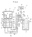
- FIG. 2 shows a modified version of the photosensitive material processing apparatus shown in FIG. 1.
- the apparatus generally designated at 1' includes an auxiliary tank 9 in which the discharge ends of the feed conduits 7a-7c and 7w are located.
- An additional feed conduit 91 at one end is connected to the auxiliary tank 9 near the bottom and at another end forms a feed port 21.
- a valve (not shown), especially an electromagnetic valve which is controllable for opening and closing timing, may be provided intermediate the feed conduit 91.
- the auxiliary tank 9 is separate from the processing tank 2 in the illustrated embodiment, but may be integrally molded with the latter.
- Predetermined amounts of partial stocks A-C and diluent water are fed into the auxiliary tank 9 through the feed conduits 7a-7c and 7w where they are mixed to form the desired replenisher Q1.
- the replenisher Q1 is then passed through the feed conduit 91 and fed into the processing tank 2 through the feed port 21.
- the auxiliary tank 9 which acts as a buffer in the replenishing procedure may be of a reduced size as compared with the storage tank 5.
- the photosensitive material processing apparatus 1 illustrated in FIG. 1 is designed such that the partial stocks A-C and diluent are directly admitted into the processing tank 2 whereas the apparatus 1' of FIG. 2 uses the auxiliary tank 9 located upstream of the processing tank 2 for premixing the partial stocks and water before entry to the processing tank 2 so that the replenisher as admitted to the tank 2 is more uniform, minimizing a local variation in the composition of the processing solution in the tank 2.
- FIG. 3 shows another modified version of the photosensitive material processing apparatus shown in FIG. 1.
- the pump used in conjunction with the feed-conduits in this embodiment is a bellows pump assembly 10. More particularly, bellows 10a, 10b, 10c and 10w having check valves built therein (not shown) are located intermediate the feed conduits 7a, 7b, 7c and 7w.
- the bellows are secured at one end to a base plate and at another end to an arm 101 which is pivoted at 102 to the base plate.
- the partial stocks A-C and diluent are fed in one direction by the action of the check valves in the bellows.
- the discharge amount of the bellows 10a-10c and 10w that is, the feed amount of the partial stocks A-C and diluent are controlled by the stroke of the respective bellows, which correspond to the distance between the attachment of the respective bellows and the pivot 102.
- the discharge amount of the bellows 10a-10c and 10w may also be controlled by adjusting the inner diameter of the respective bellows.
- the mixer 11 includes an elongated cylindrical tube 110 defining an interior flow path and having a convergent lower end defining a feed port 21.
- a plurality of agitator plates 111 are received in the cylindrical tube 110 in a multi-stage arrangement such that the edges of adjacent agitator plates are perpendicular to each other.
- the configuration, dimensions, and number of the twisted agitator plates 111 may be determined by taking into account the ability of mixing and agitating the partial stocks A-C with diluent.
- the cylindrical tube 110 on the peripheral wall is formed with longitudinally spaced apart inlet ports 112 and 113 which are coupled to the exit ends of feed conduits 7b and 7c, respectively.
- the cylindrical tube 110 at the top is formed with inlet ports 114 and 115 in a Y branch shape, which are coupled to the exit ends of feed conduits 7a and 7w, respectively.
- the static mixer 11 coupled to the exit ends of feed conduits 7a-7c and 7w serves to mix and agitate the partial stocks A-C and diluent therefrom to yield a replenisher with a uniform composition.
- the static mixer of the construction shown in FIG. 4 permits any desired one of the partial stocks and diluent to be introduced in the interior flow path at a suitable location along the longitudinal direction thereof.
- the partial stocks and diluent can be mixed in an appropriate order.
- FIGS. 1, 2 and 3 have been described as utilizing three partial stocks A, B and C, the number of partial stocks is not limited to three in the practice of the present invention.
- the line associated with partial stock C can be omitted.
- FIG. 5 Such a system for handling two partial stocks is illustrated in FIG. 5.
- the chemical cartridge 4 has two compartments 41 and 42 for receiving partial stocks A and B, respectively, and the storage tank 5 has two storage compartments 51 and 52 corresponding thereto.
- Feed conduits 7a and 7b extend from the storage compartments 51 and 52 to the processing tank 2.
- Pumps 8a and 8b are located intermediate the feed conduits 7a and 7b, respectively.
- an additional line associated with partial stock D should be installed.
- the automatic processor 120 includes a developing tank 121, a fixing tank 122, a washing tank 123, a squeezer section 124, and a dryer section 125 arranged in side-by-side fashion.
- the tanks 121-123 are provided with transfer means in the form of a rack having rollers and guides for passing a sheet of photosensitive material depicted by S along a predetermined path as shown by a phantom line, though the transfer means are not shown.
- Crossover racks 126, 127 and 128 are located at the interface between the respective tanks.
- the developing, fixing and washing tanks 121, 122 and 123 are filled with developer, fixer and wash solutions, respectively.
- the developer in the developing tank 121 is circulated through a conduit 133 connected at opposite ends to the bottom of the tank and having a pump 131 inserted therein.
- the fixer in the fixing tank 122 is circulated through a conduit 134 connected at opposite ends to the bottom of the tank and having a pump 132 inserted therein.
- the processor 120 After the processor 120 is loaded with an exposed photosensitive material S, it is successively transferred through developing tank 121, fixing tank 122, washing tank 123, squeezer section 124 and dryer section 125 where it is subject to development, fixation, water washing, water removal, and drying.
- the processor 120 has incorporated therein a replenishing system or a system for feeding replenishers. Since this replenishing system may be substantially the same as any one of FIGS. 1, 2, 3, and 5, it is briefly described. As shown in FIG. 6, the replenishing system includes a storage tank 150 for developer replenishment having three compartments 151, 152 and 153 for storing three partial stocks of the developer and a storage tank 154 for fixer replenishment having two compartments 155 and 156 for storing two partial stocks of the fixer.
- a cartridge 140 Disposed above the developer storage tank 150 is a cartridge 140 having integrally assembled three compartments or partial containers 141, 142 and 143 filled with three partial stocks A, B and C of the developer, respectively.
- a cartridge 144 Disposed above the fixer storage tank 154 is a cartridge 144 having integrally assembled two compartments or partial containers 145 and 146 filled with two partial stocks A' and B' of the fixer, respectively.
- the partial stocks A, B and C are fed from the compartments or partial containers 141, 142 and 143 of the cartridge 140 into the corresponding storage compartments 151, 152 and 153 of the storage tank 150.
- the partial stocks A' and B' are fed from the compartments or partial containers 145 and 146 of the cartridge 144 into the corresponding storage compartments 155 and 156 of the storage tank 154.
- Feed conduits 161, 162 and 163 having pumps 171, 172 and 173 inserted therein extend from the storage compartments 151, 152 and 153 of the storage tank 150 to the developing tank 121, respectively. By actuating the pumps 171, 172 and 173, the partial stocks A, B and C are fed to the developing tank 121.
- feed conduits 164 and 165 having pumps 174 and 175 inserted therein extend from the storage compartments 155 and 156 of the storage tank 154 to the fixing tank 122, respectively. By actuating the pumps 174 and 175, the partial stocks A' and B' are fed to the fixing tank 122.
- the replenishing system further includes a water storage tank 180 serving as a source for feeding diluent water.
- a water storage tank 180 serving as a source for feeding diluent water.
- conduits 181, 182, 183 and 184 having pumps 191, 192, 193 and 194 inserted therein.
- the conduit 181 extends to the wash tank 123 for replenishing water thereto
- the conduit 182 extends to above the crossover racks 126 and 127 for washing them with water
- the conduits 183 and 184 extend to the fixing and developing tanks 122 and 121, respectively, for replenishing diluent water thereto.
- the water storage tank 180 receives city water from a city water source through a conduit 185 as needed under the control of a valve 186, for example, by detecting the volume of water in the tank 180 to find that the volume drops below a predetermined level.
- the apparatus is of the type having a plurality of serially arranged processing tanks filled with processing solutions wherein a photosensitive material is processed by successively passing it through the plurality of processing tanks.
- a corresponding plurality of replenishing systems are associated with the plurality of processing tanks.
- One typical replenishing system includes an integrated container or cartridge defining a plurality of compartments filled with a plurality of partial stocks received in a separated manner, a storage tank having a corresponding plurality of compartments, means for separately feeding the partial stocks from the cartridge compartments to the storage tank compartments in a chicken hopper manner, and means for feeding the partial stocks from the storage tank compartments to the processing tank along with diluent water, thereby replenishing the processing solution to the tank.
- the system further includes a corresponding plurality of detector means attached to the plurality of storage tank compartments for detecting the level of the respective partial stocks therein, an indicator means for indicating the necessity of replacement of the cartridge in response to the detection signals of the detector means, and a control means electrically connected to the detector means for receiving the detection signals therefrom, for forcedly emptying the cartridge compartments of the residual partial stocks when at least one of the levels of the partial stocks detected by the detector means is below its predetermined value, and for actuating the indicator means after all the levels of the partial stocks detected by the detector means are below their predetermined values.
- the system further includes an alarm means for alarming the replacement of the cartridge, and the control means is adapted to actuate the alarm means after a predetermined amount of photosensitive material has been processed since the indicator means was actuated.
- the indicator means is actuated.
- the alarm means is actuated when a predetermined amount of photosensitive material has been processed after actuation of the indicator means, the necessity of replacement of the cartridge is timely noticed to the operator by both the indicator means and the alarm means. The operator will readily expect the proper timing of replacing the cartridge. If the predetermined amount is a critical amount beyond which no further photosensitive material can be effectively processed, the operator will readily find the proper cartridge replacing point of time.
- an automatic processor generally depicted at 310 includes a processing section 311 and a drying section 320 within a frame 312.
- the processing section 311 includes a series of a developing tank 314, a fixing tank 316 and a washing tank 318 defined by partitions 313 and arranged in a travel direction of a length or sheet of photosensitive material in the form of a film F in the illustrated embodiment.
- Disposed near an entrance slit 315 of film F to the processor 310 is a loading rack 317 for taking film F into the processor.
- a sensor 394 for detecting the entry of film F.
- the processor 310 adjacent the entrance slit 315 may be provided with an entrance platform along which film F is manually slid into the processor or an automatic loader for automatically feeding film F into the processor.
- the developing tank 314 is filled with a liquid developer, and a transfer rack 324 including transfer rollers 322 driven by a motor (not shown) for transferring film F along a predetermined (U-shaped in the illustrated embodiment) path is disposed in the tank such that the rack is immersed in the developer.
- the fixing tank 316 is filled with a liquid fixer, and a transfer rack 328 including transfer rollers 326 driven by a motor (not shown) for transferring film F along a predetermined (U-shaped in the illustrated embodiment) path is disposed in the tank such that the rack is immersed in the fixer.
- the washing tank 318 is filled with wash water, and a transfer rack 332 including transfer rollers 330 driven by a motor (not shown) for transferring film F along a predetermined (U-shaped in the illustrated embodiment) path is disposed in the tank such that the rack is immersed in the wash water.
- the liquid developer and fixer in the developing and fixing tanks 314 and 316 are fed to the respective heat exchangers 319 and 319 where heat exchange takes place and thereafter, back to the developing and fixing tanks 314 and 316.
- the liquid developer and fixer in the developing and fixing tanks 314 and 316 are then maintained at temperatures within the predetermined ranges.
- Crossover racks 334 are disposed above the interface between the developing and fixing tanks 314 and 316 and between the fixing and washing tank 316 and 318.
- Each crossover rack 334 includes clamping transfer rollers 336 and guides 338 for transferring and guiding film F from an upstream tank to a downstream tank in the travel direction of film F.
- the film F loaded into the processor 310 through the entrance slit 315 is introduced into the developing tank 314 from the loading rack 317 and passed through the developer in the developing tank 314 with the aid of the transfer rollers 322 where it is subject to development.
- the developed film F is fed from the developing tank 314 to the fixing tank 316 through the crossover rack 334 and passed through the fixer in the fixing tank 316 with the aid of the transfer rollers 326 where it is subject to fixation.
- the fixed film F is fed from the fixing tank 316 to the washing tank 318 through the crossover rack 334 and passed through the wash water in the washing tank 318 with the aid of the transfer rollers 330 where it is washed with water.
- the film F is processed in this way.
- the developing, fixing and washing tanks 314, 316 and 318 at the bottom are connected to one end of discharge conduits (not shown) which at the other end are connected to exit valves 321.
- exit valves 321 By opening the exit valves 321 when desired, the developer liquid in the developing tank 314, the fixer liquid in the fixing tank 316 and the wash water in the washing tank 318 can be discharged.
- a squeeze rack 340 Disposed between the washing tank 318 and the drying section 320 is a squeeze rack 340, which includes plural pairs of transfer/squeeze rollers 342 and guides 343 for feeding and guiding the film F to the drying section 320 while squeezing off the accompanying water.
- the drying section 320 includes a series of transfer rollers 344 arranged along the travel path of film F for transferring film F vertically downward, a fan 345 disposed near the bottom of the frame for blowing drying air, a chamber 346 having a heater built therein for heating the drying air, and spargert 347 in flow communiction with the chamber 346 for spraying heated drying air to the film F and transfer rollers 344. Disposed downstream of the last one of the transfer rollers 344 along the film travel path is a turning roller assembly 348 where the film F is turned obliquely upward.
- the processor 310 is provided with a film receptacle 349 located in the frame wall and half projecting from the frame wall for receiving film F from the turning roller assembly 348.
- the film F which has been squeezed by means of the squeeze rack 340 is moved downward by the transfer rollers 344 heated with the hot air while it is dried with the hot air injected from spargers 347. Thereafter, the film F is turned upward by the turning assembly 348 and directed to the receptacle 349 where it is accommodated.
- FIG. 10 illustrates a system for feeding replenishers to the photosensitive material processing apparatus, typically the processor 310 illustrated in FIG. 9.
- the replenisher feeding system generally designated at 325 is adapted to feed a developer replenisher to the developing tank 314 and a fixer replenisher to the fixing tank 316.
- the developer replenisher to the developer tank 314 is prepared by mixing three partial stocks (or three divided stock liquids for developer replenishment) with water
- the fixer replenisher to the fixer tank 316 is prepared by mixing a fixer replenishing stock with water.
- the developer replenishing liquid stock is previously charged in a cartridge or container 400 in a sealed manner as shown in FIG. 11. More particularly the cartridge 400 has three discrete compartments 402, 404 and 406 defined in its interior by partition walls. Each compartment is a reservoir for receiving a developer replenishing stock part or partial stock. That is, the first compartment 402 is filled with partial stock A, second compartment 404 filled with partial stock B, and third compartment 406 filled with partial stock C.
- the cartridge 400 includes outlet ports 408, 410 and 412 in communication with the first, second and third compartments 402, 404 and 406, respectively.
- the outlet ports 408, 410 and 412 of generally cylindrical configuration extend parallel in the same direction and terminates at a common plane.
- outlet ports 408, 410 and 412 are covered with sealing diaphragms 414 which are held in place by annular caps 416 threadably mounted on the outlet ports 408, 410 and 412 so that the sealing diaphragms 414 close the open ends of outlet ports 408, 410 and 412. A central portion of the sealing diaphragm on the outside is exposed through the opening of the cap.
- the cartridge 400 is provided with grips 418 on the side of outlet ports 408, 410 and 412 and on the opposite side, with which the cartridge can be manually handled.
- the fixer replenishing liquid stock is previously charged in a cartridge or container 420 in a sealed manner as shown in FIG. 12.
- the cartridge 420 defines a single chamber filled with the fixer replenishing stock and includes an outlet port 422 of generally cylindrical configuration.
- the open end of outlet port 422 is covered with a sealing diaphragm 424 which is held in place by an annular cap 426 threadably mounted on the outlet port 422 so that the sealing diaphragm 424 closes the open end of outlet port 422.
- the cartridge 420 is provided with grips 428 on the side of outlet port 422 and on the opposite side, with which the cartridge can be manually handled.
- the replenisher feeding system 325 includes a supply section 430 for accommodating the cartridges 400 and 420 and supplying the developer partial stocks and fixer stock in the cartridges 400 and 420 to a storage tank 350 which will be described later.
- the supply section 430 is shown at the left of FIG. 10 and described in detail by referring to FIGS. 13 to 16.
- the supply section 430 is located on one side of the processor frame 312 in a transverse direction of film F being transferred through the processor 310.
- the supply section 430 is on a side of the processor frame 312 facing the viewer in FIG. 9.
- the supply sections 430 includes an exterior lid member 432 defining part of the side wall of the processor 310 and a receptacle 434 secured to the inside of the exterior lid member 432 for accommodating the cartridges therein.
- the receptacle 434 is of a box configuration open at the top as best shown in FIG. 315 and of the size to accommodate both the cartridges 400 and 420 therein.
- the cartridge receptacle 434 at the bottom is provided with a plurality of, four in this embodiment, mating, means 435 which correspond to the outlet ports 408, 410, 412 and 422 of the cartridges 400 and 420 as shown in FIG. 14. Since these mating means 435 are of substantially the same configuration, one mating means 435 corresponding to the first compartment 402 filled with partial stock A of the cartridge 400 is described as a representative.
- the mating means 435 includes a liquid reservoir 436 of an inverted hat shape.
- the reservoir 436 is placed in the receptacle 434 with its bottom 436B in abutment with the receptacle bottom.
- the reservoir 436 at the top has a circumferential flange 436 secured by screws 440 to a circumferential bracket 438 which is, in turn, secured to the side wall of the cartridge receptacle 434.
- a projection 442 is located at the center of the reservoir bottom 436B.
- the projection 442 consists of four plate segments 442A assembled in substantially crisscross in a horizontal cross section as seen from the top view of FIG. 14A.
- the plate segments 442 each are divergent from the top to the bottom with their top portions being rounded into a continuous arcuate shape.
- the projection 442 may be formed from a single member to the same or similar shape.
- the projection 442 may be secured to the receptacle bottom 436B or simply placed thereon.
- the mating means 435 further includes a connecting port 136D in the receptacle bottom 436B spaced away from the projection 142 on the receptacle bottom 436B.
- the connecting port 136D defines a flow path 436 inside and extends downward through the receptacle bottom 436B.
- To the connecting port 436D is connected a flexible tube 444 whose other end terminates in the storage tank 350.
- the projection 442 engages the sealing diaphragms 414 in the cap 116 on the outlet port 408 of the first compartment 102 to break or move upward the sealing diaphragm 414 as shown in FIG. 14, allowing the partial stock A in the cartridge compartment 402 to flow in the reservoir 436 space and then to the storage tank 350 through the flow path 436 of the connecting port 436D and tube 444.
- a cutting edge or any other seal breaking means may be used instead of the projection 442 insofar as the outlet port of the cartridge compartment is unsealed for fluid communication.
- the liquid partial stock A spills into the reservoir 136 through the gap between the projection 442 and the cap 416.
- the cartridge receptacle 434 is placed at substantially the same height as the storage tank 350 such that the spillage of liquid partial stock A into the reservoir 436 may stop when the liquid surface reaches a predetermined level. Since the mating means 435 are provided in conjunction with the outlet ports 408, 410, 412 and 422 of the cartridges 400 and 420 as previously described, the developer partial stocks A, B and C and the fixer stock are supplied to the storage tank 350 as soon as the cartridges 400 and 420 are mounted in the receptacle 434.
- the supply section 430 of the above-mentioned construction is pivotally supported at the lower end of the exterior lid member 432. More particularly, a pair of legs 148 extend downward from the lower edge of the exterior lid member 432 as shown in FIG. 13.
- Each leg 448 as shown in FIG. 16, is a generally U shaped member having opposed walls in which slots 448A extending upward from the lower edge are formed in alignment.
- supports 450 are fixedly secured to a bottom plate 310A of the frame for supporting the legs 448 as shown in FIG. 13. More particularly, each support 450 is an upward facing generally U shaped member having opposed walls in which through holes 450A are formed in alignment.
- a pivot member 452 is inserted through the holes 450A and axially secured to the support 450 by E rings 454 mounted on the pivot member 452 adjacent the holes 450A.
- the leg 448 is fitted within the opposed walls of the support 450 such that the pivot member 452 engages the slots 448 in the leg 448.
- the supply section 430 is installed for pivotal motion about the pivot 452 between open and closed positions.
- the pivotal mount is not limited to the illustrated embodiment.
- the supply section 430 may be installed by inserting a length of bolt through the holes 450A, engaging a nut to the tip of the bolt, and mounting the receptacle 434 such that the bolt engages the slots 448A in the leg 448 walls.
- the processor 310 includes a retainer means 458 located above the supply section 430 for holding the supply section 430 in the closed position by engaging with a tab (not shown) inside the exterior lid 132 of the supply section 430. It is to be noted that the supply section 430 is illustrated in the open position in FIG. 13. The locking engagement of the retainer means 458 with the exterior lid 432 tab is released by rotating the retainer means 458a predetermined angle.
- the cartridge receptacle 434 of the supply section 430 is attached to the interior frame of the processor through a gas damper (not shown).
- the gas damper not only allows for smooth pivotal motion of the supply section 430 between the closed position where the cartridges 400 and 420 are accommodaded in place and the open position where the cartridges 400 and 420 can be installed or withdrawn, but also limit the pivotal motion of the supply secticn 430 within a predetermined angular range.
- the gas damper is set so as to limit the pivotal motion of the supply section 430 to the range of 15 degrees from the closed or vertical position as shown in FIG. 15.
- a cover 456 is fitted in the processor frame below the supply section 430 as, shown in FIG. 13 such that the cover 456 covers the legs 448 and supports 450 for aesthetic appearance.
- the automatic processor 310 at the rear side of the frame opposite to the side where the supply section 430 is installed, is further provided with a similar pivotal mount structure which is covered with a removable cover, though the rear pivotal mount structure is not shown.
- the rear pivotal mount structure includes supports similar to the supports 450 on the processor bottom plate 310A. Then, the supply section 430 can be simply removed from the front side of the processor 310 by withdrawing it upward to disengage the leg slots 448A from the pivots 452 and disconnecting the gas damper if any, and then attached again to the rear side thereof by fitting in place.
- the storage tank 350 Installed on the bottom plate 310A of the processor 310 is the storage tank 350.
- the storage tank 350 includes four compartments defined by partitions. That is, the storage tank 350 includes first, second, third and fourth compartments 350A,350A,350C and 50D which correspond to the first, second and third compartments 402, 404 and 406 of the developer cartridge 400 and the fixer cartridge 420, respectively.
- the first compartment 350A receives and stores the developer partial stock A from the first compartment 402 of the cartridge 400
- the second compartment 350B receives and stores the developer partial stock B from the second compartment 404 of the cartridge 400
- the third compartment 350C receives and stores the developer partial stock C from the third compartment 406 of the cartridge 400
- the fourth compartment 350D receives and stores the fixer stock from the cartridge 420
- a water supply tank 462 for receiving and storing city water as shown at the right in FIG. 10.
- the water tank is located backward of the squeeze rack 340 to the viewer in FIG. 9.
- the processor 310 further includes a first mixing tank 358 for preparing a developer replenisher prior to entry to the developing tank 314 and a second mixing tank 360 for preparing a fixer replenisher prior to entry to the fixing tank 316.
- feed conduits 362A, 362B and 362C having bellows pumps 364A, 364B and 364C inserted therein connect the first, second and third compartments 350A, 350B and 350C to the first mixing tank 358.
- a feed conduit 366A having a bellows pump 368A inserted therein connects the water tank 3162 to the first mixing tank 358.
- the developer partial stock A in the first compartment 350A, developer partial stock B in the second compartment 350B, developer partial stock C in the third compartment 350C, and water in the water tank 462 are supplied to the first mixing tank 58 through the feed conduits 362A, 362B, 362C and 366A, respectively.
- the first mixing tank 358 mixes developer partial stocks A, B and C and dilutes the mixture with water at the same time to prepare a developer replenisher to be fed to the developing tank 314.
- a feed conduit 62D having a bellows pump 364D inserted therein connects the fourth compartment 350D to the second mixing tank 360.
- a feed conduit 366B having a bellows pump 368B inserted therein connects the water tank 462 to the second mixing tank 360.
- a conduit 371 having a circulating pump 372 inserted therein is connected at either end to the developing tank 314 for circulating the developer liquid through the tank.
- a feed conduit 370 at one end is connected to the first mixing tank 358 and the other end of feed conduit 370 connected to the conduit 371 upstream of the pump 372. With the operation of the circulating pump 372, the developer replenisher formed in the first mixing tank 358 is fed to the developing tank 314 through the conduit 370 and 371 while it is mixed with part of the developer circulating through the conduit 371, accomplishing addition of the replenisher to the developer.
- a conduit 375 having a circulating pump 376 inserted therein is connected at either end to the fixing tank 316 for circulating the fixer liquid through the tank.
- a feed conduit 374 at one end is connected to the second mixing tank 60 and the other end of feed conduit 374 connected to the conduit 375 upstream of the pump 376.
- the water supply tank 462 for receiving and storing city water shown at the right in FIG. 310 is located backward of the squeeze rack 340 to the viewer in FIG. 9.
- the detail of water supply tank 462 is shown in FIG. 19.
- the water tank 462 includes a rectangular housing the interior of which is divided into first, second and third compartments 470, 468 and 472 by partitions 464 and 466.
- the first compartment 470 receives city water through a conduit 390 which is connected to a tap via a solenoid valve 392.
- the partition 466 is lower than the peripheral wall of the tank 462 so that the water supplied to the first compartment 470 will flow over the partition166 into the third compartment 472.
- the partition is approximately as high as the peripheral wall of the tank 464.
- the partition 464 is formed with a slot 476 as shown in FIG. 19A which extends downward from the top edge and terminates at a position slightly lower than the top edge of the partition 166, so that the first and second compartments 470 and 468 are in flow communication through the slot 476.
- a plurality of slots may be formed if desired.
- the water supplied to the first compartment 470 not only flows down into the third compartment 472 but is also distributed to the second compartment 468 through the slot 476.
- the means for communicating the first compartment 470 to second compartment 468 is not limited to the slot 476 and any desired communication structures such as a horizontal slot near the water surface may be utilized.
- Means 480 for releasing silver ions to control the growth of algae is disposed at the bottom of the second compartment 468.
- the means 468 includes a source for releasing silver ions 482 and a water permeable container 484 having the source received therein.
- the silver ion releasing source 482 may be a water leachable glass containing monovalent Ag.
- the water leachable glass is comprised of at least one network forming oxide selected from SiO2, B2O3 and P2O5, at least one network modifying oxide selected from Na2O, K2O, CaO, MgO, BaO and ZnO, and at least one intermediate oxide selected from Al2O3 and TiO2 and contains 0.05 to 10% by weight, preferably 0.1 to 5% by weight of Ag2O.
- the amorphous water-soluble glass becomes gel in water, retains a given amount of silver cations in the gel, and gradually releases silver cations into water.
- the glass may be in a mass, granular or powder form. It is received in a water-permeable container (e.g., a non-woven fabric bag) which is placed in water.
- a mass of water-leachable glass may be used by receiving it in a mesh bag and suspending the bag in water with a string.
- the water-leachable glass is used in an amount of 1,000 to 100,000 grams per cubic meter of the volume of the second wash water compartment 468.
- Such a water-leachable glass is commercially available as Biosure SG from Kinki Pipe Giken K.K. of Japan.
- any other silver cation sustained release sources may be used as long as they allow Ag+ to be dissolved out in trace increments in exchange with H+ in water.
- Stain Killer commercially available from Keiyo K.K. may be Used.
- Another example of the silver cation release means 480 is means for electrically releasing silver cations in water on the basis of the Electro-Katadyn process. This is embodied by a pair of electrodes of silver or silver-copper alloy immersed in water. Conduction of electricity across the electrodes causes a trace amount of Ag+ ions to be dissolved away.
- One commercially available controller is Caribbean Clear swimming Pool Purifier marketed from Caribbean Clear International of Columbia, South Carolina, U.S.A.
- the silver cation release means is preferably controlled such that when immersed in or contacted with about 10 liters of static water at room temperature, it will release Ag+ in a concentration of about 1 to 10,000 ppb, especially about 30 to 1,000 ppb after 24 hours.
- the compartments 350A, 350B, 350C and 350D of the storage tank 350 are provided on a side wall upper portion with level sensors 352A, 352B, 352C and 352D for detecting the surface of the respective replenisher stock liquids.
- These level sensors 352 are connected to an input port380D of a control means 380 as shown in FIG. 17 for delivering the detected signals regarding the surface of the respective replenisher stock liquids to the control means 380.
- the control means 380 includes a CPU 380A, a ROM 380B, a RAM 380C, an input port 380D and an output port 380E linked through a data bus 380F.
- the control means 380 is designed so as to judge that when the liquid level detected by a respective one of the sensors 352 is below a predetermined value, a corresponding one of the compartments of the developer cartridge 400 and the fixer cartridge 420 is emptied of the developer partial stock or fixer stock.
- the bellows pumps 364A to 364D in the feed conduits 362A to 362D connected to the compartments 350A to 350D are coupled to the output port 380E of the control means 380 such that the control means controls the operation of the bellows pumps.
- the water tank 462 is provided on a side wall upper portion with a level sensor 186 for detecting the surface of water.
- This level sensor 186 is coupled to the input port 380D of the control means 380 as shown in FIG. 17 for delivering the detected signal regarding the surface of water to the control means 380.
- the control means 380 judges the necessity of making up city water when the water level detected by the sensor 486 is below a predetermined value.
- the bellows pumps 368A and 368B in the feed conduits 366A and 366B connected between the water tank 462 and the mixing tanks 358 and 360 are coupled to the output port 380E of the control means 380 which controls the operation of the bellows pumps so as to supply predetermined amounts of water to the mixing tanks 358 and 310.
- the sensor 394 located at the entrance 15 of the processor 310 for detecting the entry of film F (FIG. 9) is also coupled to the input port 380D of the control means 380 as shown in FIG. 17. Based on the detection result of the loading sensor 394, the control means 380 computes the amount of film F processed, that is, the cumulative surface area of film processed and actuates the bellows pumps 364A to 364D and 368A and 368B to supply the developer and fixer replenishers to the corresponding tanks.
- the indicator lamp 382 for indicating replacement provides three types of lighting using a green light and a red light which can be operated or flickered.
- the control means 380 controls the replacement indicating lamp 382 so as to turn on the green light during normal supply of replenishers, turn on the red light to indicate the replacement of the cartridges 400 and 420 to the operator, and flicker the red light to alarm the urgent replacement of the cartridges 400 and 420 to the operator.
- the control means 380 also has the liquid crystal display 384 represent a message to the operator.
- An imagewise exposed film F is first loaded into the processor 310 through entrance slit 315, passed through developing, fixing and washing tanks 314, 316 and 318 where it is subject to processing with the developer, fixer and wash water, and then fed to squeezer section 340 where it is squeezed of water.
- the processed film F is then dried in drying section 320 with hot air and heated transfer rollers 344 and finally delivered to receptacle 349 through reverse roller 318.
- the processor 310 is successively loaded with sheets of film F which are processed as above and accommodated in receptacle 349.
- the fixer in fixing tank 316 is also gradually exhausted. Therefore, it is necessary to make up a predetermined amount of fixer replenisher from mixing tank 360 to fixing tank 316 at predetermined intervals or in accordance with a predetermined amount of film processed. Replenishment is conducted by actuating circulation pump 376 whereby the fixer replenisher is mixed with part of the fixer in fixing tank 316 before entry into the tank. This minimizes a variation in the distribution of the fixer components in fixing tank 316 at the time of replenishment.
- replenisher feed system 325 associated with photosensitive material processing apparatus 310 that carries out supply of replenisher stocks to mixing tanks 358 and 360.
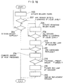
- the operation of system 325 for feeding replenisher stocks is now described by following the flow diagram of FIG. 18.
- the control means of system 325 is programmed such that the volume of the developer and fixer replenishers in mixing tanks 358 and 360 are monitored, the algorithm in the flow diagram is executed when each liquid volume is lowered below a predetermined level, and a predetermined amount of developer replenisher stocks or fixer replenisher stock is supplied to the corresponding mixing tank.
- the cartridges 400 and 420 are installed in receptacle 134 of supply section 430 until their outlet ports 408,410, 412 and 422 fit with mating means 435 to open the seals. Then the replenisher stocks are supplied from the cartridge compartments to compartments 350A-350D of storage tank 350 in a chicken hopper manner. The surface of the replenisher stocks in storage tank compartments 350A -350D are detected by sensors 352A-352D and the detected signals delivered to control means 380. Then control means 380 causes indicator lamp 382 to turn on the green light and display 384 to represent the message "film Developable".
- Step 200 is to actuate bellows pumps 364A, 364B, 364C and 364D to thereby supply a predetermined amount of developer partial stocks A, B and C from storage tank compartments 350A, 350B and 350C to first mixing tank 358 and a predetermined amount of fixer stock from storage tank compartment 350D to second mixing tank 360.
- the volume of liquid stocks in compartments 350A, 350B, 350C and 350D decreases, the balance between the atmospheric pressure and the weight of the liquid stocks in the respective compartments is lost, causing the liquid stock in cartridges and to drain out to the reservoirs 436 and flow to compartments 350A, 350B, 350C and 350D until the surface of liquid stocks in compartments 350A, 350B, 350C and 350D are restored to the preset level.
- Such continuous supply is repeated to keep storage tank compartments 350A, 350B and 350C full of developer replenisher partial stocks A, B and C from cartridge 400 and the storage tank compartments 350D full of fixer replenisher stock from cartridge 420 at all times.
- Step 202 is to judge whether or not any one of the liquid levels detected by sensors 352A, 352B, 352C and 352D is below the predetermined value. If all the liquid levels are above the predetermined values, the algorithm shifts to step 204 to judge whether or not the given amounts of replenisher stocks have been supplied. If the given amounts of replenisher stocks have not been supplied, the judgment of step 204 is denied (NO). Then steps 200 and 204 are repeated until the given amounts of replenisher stocks have been supplied. The replenishing procedure comes to an end when the given amounts of replenisher stocks have been supplied.
- the bellows pumps 364A to 364D which are actuated upon replenishment tend to pump variable amounts of liquid stocks to mixing tanks 358 and 360 because the bellows are molded to the desired configuration with tolerances and some other reasons.
- the cartridge volume is designed such that developer partial stocks A, B and C in compartments 402, 404 and 406 of cartridge 400 and fixer stock in cartridge 420 are consumed in proportional amounts and become empty at the same time, there is a likelihood that the amount of a certain stock consumed vary from the remaining ones.
- One possible situation is that although developer partial stock A is fully consumed and cartridge first compartment 402 becomes empty, some amount of developer partial stock B and C and fixer stock still remain in cartridges 400 and 420. In this situation, only the liquid level detected by sensor 352A is below the predetermined value. Then the judgment of step 202 becomes affirmative (YES), leading to replenishment of replenisher stocks or replacement of the cartridges in the following procedure.
- Step 206 is to actuate the bellows pumps other than that bellows pump corresponding to the line where a lowering of the liquid level is detected.
- the remaining bellows pumps 352B, 352C and 352D corresponding to developer partial stocks B and C and the fixer stock are actuated.
- Step 208 is to judge whether or not all the liquid levels detected by sensors 352A, 352B, 352C and 52D are below the predetermined values. If any one of the liquid levels is above the predetermined value, steps 206 and 208 are repeated until all the liquid levels detected by sensors 352A, 352B, 352C and 352D become below the predetermined values. It is, however, desired to supply the residual replenisher stocks such that the developer replenisher in mixing tank 358 and the fixer replenisher in mixing tank 360 do not deviate from their acceptable range.
- step 210 acts on indicator lamp 382 to light the red lamp for indicating to the operator the necessity of replacement of the cartridges.
- indicator lamp 382 acts on indicator lamp 382 to light the red lamp for indicating to the operator the necessity of replacement of the cartridges.
- Step 212 is to judge whether or not the operator has replaced cartridges 100 and 120. Replacement of the cartridges may be judged, for example, by detecting that the retainer member is engaged in place. The replenishing procedure comes to an end when the judgment of step 212 is YES. If the judgment of step 212 is NO, the algorithm shifts to step 214 to compute, on the basis of a detected signal of loading sensor 394, the amount or accumulative surface area of film processed since the lighting of the red lamp of indicator means 382. Step 216 is to judge whether or not the computed amount of film processed exceeds a predetermined processing amount. The predetermined amount may be set to an amount corresponding to 200 quarter-size sheets of film. If the judgment of step 216 is NO, the algorithm goes back to step 212. Steps 212 to 216 are repeated until the cartridges are replaced or the amount of film processed exceeds the predetermined amount.
- step 216 If the judgment of step 216 is YES, the algorithm shifts to a step 218 to flicker the red lamp of indicator means 382.
- Step 218 is also programmed to represent a message "Replace Cartridge" on display 384, providing an alarm of urgent cartridge replacement to the operators step 220.
- the indicator lamp 382 is lighted. With the red lamp on, the operator will readily notice the necessity of cartridge replacement.
- the means 382 for indicating the replacement of cartridges is described as a set of lamps in the illustrated embodiment although any desired indicators with which the operator will notice the necessity of replacement may be used, for example, a buzzer.
- the residual liquid replenisher stocks in the cartridges are forcedly drained to the mixing tanks by actuating the bellows pumps although the present invention is not limited thereto.
- exhaust conduits having valves mounted therein are connected to compartments 350A to 350D of storage tank 350 so that the residual liquid replenisher stocks in the cartridges and the storage tank compartments may be drained and discarded.
- the system further includes a line for washing crossover racks 334 (see FIG. 9), which includes the water tank 462, a conduit 504 extending from the bottom of water tank compartment 468 (see FIG. 19) to crossover rack 334 (see FIG. 20), and a pump (not shown) in the conduit.
- the terminal portion of conduit 504 lies on the partition 13 and is formed with orifices 506 as shown in FIG. 20.
- the crossover racks 334 are washed at the end of operation of automatic processor 310, for example, at the end of daily film processing. More particularly, at the end of routine operation of processor 310, the pump is actuated to pump water from compartment 468 through conduit 504. Water is injected through orifices 506 toward crossover rack 34, particularly clamping transfer rollers 336 and guide plates 338. After a predetermined time, the pump is stopped, ceasing to wash crossover racks 334.
- conduit 504 Some water remains in conduit 504 after the pump is interrupted. This water contains silver ions released from silver ion release means 480 which are effective in controlling the growth of bio-slime or algae. Since orifices 506 are prevented from clogging, washing of crossover racks 334 is started without disabilities at the end of subsequent (e.g, next day) operation of processor 310.
- the type of photosensitive material which can be processed in the practice of the invention is not particularly limited. Any desired types of photosensitive material may be processed, including color negative film, color reversal film, color photographic paper, color positive film, color reversal photographic paper, printing photographic photosensitive material, radiographic photosensitive material, black-and-white negative film, black-and-white photographic paper, and micro-film photosensitive material.
- the invention is adapted for the processing of black-and-white photosensitive materials among others, especially medical and industrial radiographic photosensitive materials, duplicating photographic materials for X-ray photography and medical CRT image duplicating photographic photosensitive materials, as typified by direct and indirect radiographic films and CRT duplicating films.
- the present invention can be applied to either black-and-white processing including development, fixation and washing or color processing including development, bleaching, fixation (or bleach-fixation), washing and optionally, stabilization, although best results are obtained when applied to development and fixation procedures.
- partial stocks used in the practice of the present invention are described with respect to partial stocks for black-and-white developer as a typical example.
- the black-and-white developers generally include two-and three-part compositions.
- the two-part composition consists of an alkaline partial stock containing a developing agent, referred to as partial stock A, and a partial stock containing a hardener, especially a dialdehyde hardener, referred to as partial stock C.
- the three-part composition consists of a partial stock A containing a developing agent, a partial stock B containing an auxiliary developing agent, and a partial stock C containing a hardener, especially a dialdehyde hardener.
- the developing agent and auxiliary developing agent include dihydroxybenzene developing agents, pyrazolidone developing agents, and p-aminophenol developing agents.
- Partial stock A or B may additionally contain an alkaline agent, preservative, buffer agent, chelating agent, organic solvent, antifoggant and the like.
- the dihydroxybenzene developing agents include hydroquinone, chlorohydroquinone, bromohydroquinone, isopropylhydroquinone, methylhydroquinone, 2,3 dichlorohydroquinone, 2,5-dichlorohydroquinone, 2,3-dibromohydroquinone, and 2,5-dimethylhydroquinone, with the hydroquinone being preferred.
- the partial stock preferably contains a dihydroxybenzene in an amount of about 10 to 250 grams, more preferably about 15 to 150 grams per liter of the partial stock.
- the pyrazolidone developing agents include 1-phenyl-3-pyrazolidone, 1-phenyl-4,4-dihydroxymethyl-3-pyrazolidone, 1-p-tolyl-4,4-dihydroxymethyl-3-pyrazolidone, 1-phenyl-4-hydroxymethyl-4-methyl-3-pyrazolidone, 1-phenyl-4,4-dimethyl-3-pyrazolidone, 1-phenyl-2-hydroxymethyl-4,4-dimethyl-3-pyrazolidone, 1-phenyl-2-morpholinomethyl-4,4-dimethyl-3-pyrazolidone, and 1-phenyl-2-morpholinomethyl-4-methyl-3-pyrazolidone.
- the p-aminophenol developing agents include N-methyl-p-aminophenol, p-aminophenol, N- ( ⁇ -hydroxyethyl) -p-aminophenol, N-(4-hydroxyphenyl)glycine, 2-methyl-p-aminophenol, and p-benzylaminophenol, with the N-methyl-p-aminophenol being preferred.
- the preservatives include sodium sulfite, potassium sulfite, lithium sulfite, ammonium sulfite, sodium bisulfite, and potassium metabisulfite.
- additives include development inhibitors such as sodium bromide, potassium bromide and potassium iodide; organic solvents such as ethylene glycol, diethylene glycol, triethylene glycol, dimethylformamide, methyl cellosolve, hexylene glycol, ethanol, and methanol; and antifoggants, for example, mercapto compounds such as 1-phenyl-5-mercaptotetrazole and sodium 2-mercaptobenzimidazole-5-sulfonate and benzotriazole compounds such as 5-methylbenzotriazole.
- any toning agents, surface active agents, defoaming agents, water softeners, and especially amino compounds as disclosed in JP-A 106244/1981 may be contained.
- the dialdehyde hardeners contained in partial stock C include glutaraldehyde, ⁇ -methylglutaraldehyde, ⁇ -methylglutaraldehyde, maleindialdehyde, succindialdehyde, methoxy-succindialdehyde, methylsuccindialdehyde, ⁇ -methoxy- ⁇ -ethoxyglutaraldehyde, ⁇ -n-butoxyglutaraldehyde, ⁇ , ⁇ -dimethoxysuccindialdehyde, ⁇ -isopropylsuccindialdehyde, ⁇ , ⁇ -diethylsuccindialdehyde, butylmaleindialdehyde, and bisulfite adducts thereof.
- Partial stock C preferably contains dialdehyde hardeners in an amount of about 50 to 400 grams, more preferably about 100 to 300 grams per liter of the partial stock.
- Partial stocks B and C may further contain acids such as acetic acid and indazole compounds such as 5-nitro-indazoles.
- the fixer is usually an aqueous solution containing a thiosulfate at pH 3.8 or higher, preferably 4.2 to 7.0.
- the fixing agents include sodium thiosulfate and ammonium thiosulfate, with the ammonium thiosulfate being preferred for fixing rate.
- the amount of the fixing agent used may be suitably chosen although it usually ranges from about 0.1 to about 6 mol/1.
- the fixer may contain water-soluble aluminum salts having a hardener function, for example, aluminum chloride, aluminum sulfate and potassium alum.
- the fixer may contain tartaric acid, citric acid, gluconic acid and derivatives thereof alone or in admixture of two or more. These compounds are preferably contained in amounts of at least 0.005 mol, more preferably 0.01 to 0.03 mol per liter of the fixer.
- the fixer may contain preservatives (e.g., sulfites and bisulfites), pH buffer agents (e.g., acetic acid and boric acid), chelating agents capable of softening hard water, and compounds capable of promoting dissolution of sensitizing dyes as disclosed in JP-A Nos. 4739/1989 and 15734/1989 and Japanese Patent Application Nos. 17776/1988, 256807/1988, 114458/1989 and 136579/1989.
- preservatives e.g., sulfites and bisulfites
- pH buffer agents e.g., acetic acid and boric acid
- chelating agents capable of softening hard water
- compounds capable of promoting dissolution of sensitizing dyes as disclosed in JP-A Nos. 4739/1989 and 15734/1989 and Japanese Patent Application Nos. 17776/1988, 256807/1988, 114458/1989 and 136579/1989.
- the fixers generally include two- and one-part compositions.
- the fixer composition is often divided into two parts, that is, a hardener part containing an acidic hardener, typically a water-soluble aluminum salt, referred to as partial stock B, and another part containing the fixer components other than the hardener part components, referred to as partial stock A.
- the hardener may be contained in partial stock A, which results in a one-part composition.
- the composition should preferably be adjusted to pH 4.5 or higher in order to improve the stability of thiosulfate ions, known as sulfide life.
- the volume ratio of-partial stocks should preferably be up to 15, especially up to 10.
- developer time and “fixing time” used in this disclosure mean the time from the dipping of photosensitive material in a developer bath in an automatic processor to the subsequent dipping in a fixer bath and the time from the dipping of photosensitive material in the fixer bath to the subsequent dipping in a wash or stabilizing bath, respectively.
- wash time is the time during which the photosensitive material is dipped in wash water.
- drying time is the time during which the photosensitive material is passed through the drying section in the processor, through which generally hot air at a temperature of about 35 to 100°C, preferably 40 to 80°C is blown.
- the photosensitive material which has been exposed imagewise is developed, fixed and then washed or stabilized.
- the washing process may use any of well-known techniques.
- the washing process includes not only conventional washing processes, but also water saving washing processes and stabilizing processes.
- Water containing various additives well known in the art may be used as the wash water or stabilizer.
- Use of water having antifungal means applied thereto as the wash water or stabilizer leads to water saving as demonstrated by a replenishing amount of up to 3 liters per square meter of photosensitive material and eliminates piping operation in installing the processor.
- One known method for reducing replenishing amounts is a multi-stage (e.g., two or three-stage), counter-flow system. More efficient water washing is achieved with the multi-stage, counter-flow system since the photosensitive material after fixation is processed in a gradually cleaner direction, that is, by successively contacting with processing solutions which are gradually less contaminated with the fixer. Where washing is done with a less amount of wash water, it is desired to provide a squeeze roller washing tank as disclosed in Japanese Patent Application No. 172968/1985.
- the antifungal means used herein includes UV irradiation as disclosed in JP-A 263939/1985, magnetic field application as disclosed in JP-A 263940/1985, passage through ion-exchange resins to produce pure water as disclosed in JP-A 131632/1986, and addition of antifungal agents as disclosed in Japanese Patent Application Nos. 253807/1985, 295894/1985, 63030/1986, 51396/1986, and 91533/1989. Also useful are fungicidal agents, bactericidal agents, and surface active agents as disclosed in L. E. West, "Water Quality Criteria", Phto. Sci. & Eng., Vol. 9, No. 6 (1965), M. W.
- the wash bath may further contain microbiocides, for example, the isothiazolines described in R. T. Kreiman, J. Imaging Tech., 10, 6 (1984), the isothiazolines described in Research Disclosure, Vol. 205, Item 20526 (May 1981), the isothiazolines described in Research Disclosure, Vol. 228, Item 22845 (April 1983), and the compounds described in Japanese Patent Application No. 51396/1986.
- microbiocides for example, the isothiazolines described in R. T. Kreiman, J. Imaging Tech., 10, 6 (1984), the isothiazolines described in Research Disclosure, Vol. 205, Item 20526 (May 1981), the isothiazolines described in Research Disclosure, Vol. 228, Item 22845 (April 1983), and the compounds described in Japanese Patent Application No. 51396/1986.
- the preferred set of washing or stabilizing temperature and time includes about 0 to 50°C for about 6 seconds to 2 minutes, more preferably about 15 to 40°C for about 6 to 60 seconds, most preferably about 15 to 40°C for about 6 to 25 seconds.
- a replenisher for a black-and-white developer was prepared from the following three partial stocks.
- Glutaraldehyde 50 wt/wt %) 150 g Potassium metabisulfite 150 g Water totaling to 750 ml
- a polyethylene container of the structure shown at 4 in FIG. 2 was used whose interior was divided into a first compartment having a volume of 4.6 liters, a second compartment having a volume of 0.9 liters, and a third compartment having a volume of 0.9 liters.
- the first compartment was filled with 4125 ml of part A
- the second compartment was filled with 750 ml of part B
- the third compartment was filled with 750 ml of part C.
- the outlet ports of the compartments was closed with foam polyethylene seals held in place by polypropylene caps.
- Storage tank Volume Compartment for part A 5 liters Compartment for part B 0.9 liters Compartment for part C 0.9 liters Total 6.8 liters
- a modified version of automatic processor model FPM 9000 manufactured by Fuji Photo Film Corporation was used. It had a series of processing tanks in the arrangement shown in FIG. 6. The tanks had the following volume. Developing tank 15 liters Fixing tank 15 liters Washing tank 13 liters
- Biosure SG is a leachable glass of Na2O/B2O5/SiO2 containing 0.5% by weight of Ag2O having an antifungal function.
- the temperature was raised to 56°C, 186 mg of 4-hydroxy-6-methyl-1,3,3a,7-tetraazaindene was then added, and after 10 minutes, 520 mg of a sensitizing dye of the following structural formula was added.
- a coating solution was prepared by adding the following chemical substances to the emulsion, the amount being expressed per mol of silver halide.
- Polymer latex poly(ethylacrylate/methacrylic acid) (97/3) 25.0 g
- 2,6-bis(hydroxyamino)-4-diethylamino-1,3,5-triazine 80 mg
- Polyacrylamide 24 g (average molecular weight 45,000)
- a support was prepared by coating a blue-tinted polyethylene terephthalate base of 175 ⁇ m thick on either surface with an undercoat in the following coating weight.
- the coating solution was coated on either surface of the transparent PET support of 175 ⁇ m thick at the same time as a surface protective layer coating solution.
- the coating weight was 2.0 g of silver per square meter on each surface.
- the surface protective layer coating solution was prepared by blending the following components such that they provided the following coating weight.
- the thus prepared sheet photosensitive material was cut to the quarter size of 10 inches by 12 inches, imagewise exposed with X-rays, and subjected to an experiment.
- the cartridge compartments filled with parts A, B and C was unsealed by breaking the foam polyethylene seals attached to the compartment outlet ports with cutting edges on the storage tank, allowing the respective partial stocks from the cartridge in their entirety to flow down into the corresponding compartments of the storage tank.
- the compartments of the storage tank were equipped with level sensors for detecting the surface of the associated liquids, which were interconnected to alarm means for indicating the necessity of refilling the partial stocks.
- the partial stocks in the storage tank and diluent water were fed in the following proportion to the developing tank through an auxiliary tank.
- the replenisher was fed every 8 quarter-size sheets of photosensitive material being processed.
- Development replenisher Part A 55 ml Part B 10 ml Part C 10 ml Diluent water 125 ml pH 10.50
- Wash water was fed at a flow rate of 10 liter/minute in an amount of about 1 liter per quarter-size sheet during processing of the photosensitive material by opening an electromagnetic valve in a replenishing water line in synchronization with the entry of the photosensitive material.
- the wash tank was emptied of the wash water in its entirety by automatically opening an electromagnetic valve associated with the discharge port of the wash tank.
- the storage tank was charged with 4125 ml of part A, 750 ml of part B, 750 ml of part C, and 9375 ml of diluent water, which were agitated and mixed to prepare a replenisher.
- the replenisher was fed to the developing tank in an amount of 200 ml every 8 quarter-size sheets of X-ray exposed photosensitive material being processed.
- Comparative Example 1 needed a large size storage tank having a volume of 25 liters to provide 15 liters of developer replenisher whereas Example 1 used a small size storage tank having a total volume of 6.8 liters to provide the same volume of developer replenisher.
- the storage tank of such a small size could be installed to the processor in a side-by-side relationship.
- Example 1 was very easy to operate since the respective partial stocks can be transferred to the storage tank compartments by a single operation.
- the system of Comparative Example 1 required a cumbersome, time-consuming operation to admit the partial stocks into the storage tank because the partial stocks were filled in the separate bottles.
- Example 1 no variation in composition or concentration of the developer replenisher occurred from the start to the end of replenishment.
- the overall arrangement of the processor was the same as in Example 1. Using the system of the construction shown in FIG. 5, a replenisher for a black-and-white fixer was prepared from the following two partial stocks.
- Ammonium thiosulfate (70 wt/vol %) 3 liters Disodium ethylenediaminetetraacetate dihydrate 0.45 g Sodium thiosulfate pentahydrate 150 g Sodium sulfite 375 g Tartaric acid 48 g Glacial acetic acid 472.5 g Sodium hydroxide 165 g 1-(N,N'-dimethylamino)ethyl-5-mercaptotetrazole 15 g Water totaling to 4 liters pH 5.5
- a polyethylene container of the structure shown at 4 in FIG. 5 was used whose interior was divided into a first compartment having a volume of 5 liters and a second compartment having a volume of 0.76 liters.
- the first compartment was filled with 4 l of part A' and the second compartment filled with 630 ml of part B'.
- the outlet ports of the compartments was sealed as in Example 1.
- Storage tank Volume Compartment for part A' 4.8 liters Compartment for part B' 0.76 liters Total 5.56 liters
- the cartridge compartments filled with parts A' and B' was unsealed by breaking the foam polyethylene seals attached to the compartment outlet ports with cutting edges on the storage tank, allowing the respective parts from the cartridge in their entirety to flow down into the corresponding compartments of the storage tank.
- the storage tank was charged with 4 l of part A', 630 ml of part B', and 10.37 l of diluent water, which were agitated and mixed to prepare a replenisher.
- the replenisher was fed to the fixing tank in an amount of 200 ml every 8 quarter-size sheets of X-ray exposed photosensitive material being processed.
- Comparative Example 2 needed a large size storage tank having a volume of 25 liters to provide 15 liters of fixer replenisher whereas Example 1 used a small size storage tank having a total volume of 5.56 liters to provide the same volume of fixer replenisher.
- Example 2 was very easy to operate since the respective partial stocks can be transferred to the storage tank compartments by a single operation.
- the system of Comparative Example 2 required a cumbersome, time-consuming operation to admit the partial stocks into the storage tank because the partial stocks were filled in the separate bottles.
- Example 2 no variation in composition or concentration of the fixer replenisher occurred from the start to the end of replenishment.
Description
- This invention relates to a method and system in accordance with the preamble of claims 1and 8 for replenishing a processing solution to a tank for processing silver halide photosensitive material.
- Such a method and system is already disclosed in document US-A-4,329,042. The replenishment system disclosed therein comprises a compartmented storage tank and means for delivering partial stocks from the storage tank compartments in amounts corresponding to the desired mix to the processing tank along with diluent.
- Document US-4,312,595 shows an automatic fluid mixing system that comprises a housing which defines a reservoir and means for supporting a plurality of containers of chemicals, such as those defined by a multi-compartmented module. Inlet and outlet conduits respectively communicate with the reservoir via valves and respectively permit the ingress of a base liquid, such as water, in case of developer solutions, and egress of the solutions. The disposable multi-compartmented module is discontinuously opened to permit the mixing of initially released contents before the subsequent opening of the remaining compartments.
- Development of photosensitive material is generally carried out by dipping it in a processing solution in a tank of an automatic processor for a predetermined time. For continuous processing of a vast quantity of photosensitive material, a solution replenishing system is often employed to keep an effective composition of the processing solution in the tank. As a certain amount of photosensitive material is processed, a fresh processing solution referred to as a replenisher is replenished to the processing tank while the exhausted processing solution is forced out of the tank in an overflow manner.
- Some prior art systems for preparing and replenishing such a replenisher are briefly described. FIG. 7 shows one exemplary system associated with an automatic processor for X-ray photosensitive material. The illustrated system is designed to prepare a developer replenisher and supply it to a developing
tank 2 through which photosensitive material designated at S is passed. Threeindependent cartridges storage tank 12 along with a necessary volume of diluent water and agitated and mixed by a chemical mixer or the like to prepare a developer replenisher Q2. The replenisher Q2 in thestorage tank 12 is fed to the processing or developingtank 2 as desired by means of apump 13. At the same time, the exhausted solution exits thetank 2 through anoverflow pipe 22. Similarly in a fixing tank, a fixer replenisher is prepared from two partial stocks and diluent water, stored in a storage tank, and pumped to the fixing tank as desired. - The chemical agents constituting the developer and fixer are stored in a plurality of partial stocks for the purposes of avoiding interaction therebetween, preventing deterioration with time, and insuring long term shelf storage.
- This replenishing system undesirably requires a large space for installation because the
storage tank 12 must have a large volume to store replenisher Q2. To meet the recently increasing demand for compact processors, it is desired to reduce the size of the replenisher storage tank. - Another replenishing system which was developed under such circumstances eliminated a replenisher storage tank. FIG. 8 shows such a replenishing system which is designed to directly feed partial stocks A, B and C from three
independent stock cartridges feed pumps pump 17. The partial stocks A, B and C are mixed with diluent water in the sump to prepare a replenisher Q2, which is then fed to a processing or developingtank 2. Every time when thecartridges 4a to 4c become empty and are to be replaced, it is necessary to withdraw nozzles of feed tubes from the empty cartridges and connect them to new cartridges. This replacement operation is cumbersome. It seldom occurs that the partial stocks A, B and C are fully consumed at the same time without a remainder. One or two partial stocks can remain or be prematurely consumed probably because of the practical limit of accuracy of thepumps 14 to 16, but it is difficult to incorporate a correcting mechanism. It is undesirable to equip thecartridges 4a-4c with mechanisms for detecting the volume of remaining liquid because the cartridges are frequently replaced by new ones. Therefore, this system requires careful daily service and maintenance, eventually cumbersome operations and suffers from poor accuracy. - Therefore, an object of the present invention is to provide a method for replenishing a processing solution to a processing tank with efficiency and accuracy. Another object of the present invention is to provide a system for efficiently replenishing a processing solution to a processing tank, which allows the processing apparatus, in particular, a replenishing tank therein to be reduced in size while maintening accuracy of replenishment of the processing solution. This object is met by the characterizing features of
claims 1 and 8. - With the organization of the present invention, since partial stocks are temporarily stored in the discrete storage tank compartments without dilution, the storage tank as a whole can be of a reduced capacity so that the overall apparatus may be reduced in size. The partial stocks are taken out of the storage tank compartments in amounts corresponding to the desired mix proportion of the partial stocks and fed to the processing tank along with the diluent, ensuring the accuracy of replenishment. Use of an integral cartridge having partial stocks contained in discrete compartments thereof provides ease of operation. Since partial stocks are contained in the cartridge compartments in amounts corresponding to the desired mix proportion of the partial stocks, the cartridge can be replaced in a cycle generally corresponding to the full consumption of the respective partial stocks, eliminating waste of partial stocks and alleviating replacement operations.
- The above and other objects, features, and advantages of the present invention will be better understood from the following descripticn taken in conjunction with the accompanying drawings, in which:
- FIG. 1 schematically illustrates a system for replenishing a processing solution to a processing tank according to the present invention;
- FIGS. 2, 3 and 5 are schematic views similar to FIG. 1 of modified systems;
- FIG. 4 is an axial cross-sectional view of a static mixer which is used in the embodiment of FIG. 3;
- FIG.6 is a view schematically showing the overall arrangement of an automatic processor having incorporated therein replenishing systems for replenishing processing solutions according to the present invention;
- FIG. 7 and 8 are schematic views of prior art replenishing systems;
- FIG. 9 is a vertical cross-sectional view of an automatic processor to which the present invention is applied;
- FIG. 10 schematically illustrates the systems for feeding replenishers to the processing tanks of the processor of FIG. 9;
- FIG. 11 is a perspective view of a cartridge for receiving partial stocks of the developer replenisher therein;
- FIG. 12 is a perspective view of a cartridge for receiving a fixer replenisher stock therein;
- FIG. 13 is a perspective view of a supply section;
- FIG. 14 is a cross-sectional view of the mating means for receiving the cartridge outlet port and perforating the seal thereof;
- FIG. 14A is a transverse cross-sectional view of the unsealing means;
- FIG. 15 is a side view of the cartridge receptacle in an inclined state;
- FIG. 16 is an exploded perspective view of the means for pivotally mounting the cartridge receptacle;
- FIG. 17 is a block diagram of a system for controlling the replenisher feeding system;
- FIG. 18 is a flow diagram showing the operation of the control system of FIG. 17;
- FIG. 19 is a cross-sectional view of the water storage tank in the arrangement of FIG. 10;
- FIG. 19A is a fragmental perspective view of a partition in the water storage tank of FIG. 19; and
- FIG. 20 is a cross-sectional view of a crossover rack and a water sparger associated therewith. Like parts are designated by the same reference numerals throughout the figures.
- Referring to FIG. 1, there is schematically illustrated a portion of an apparatus for processing a photosensitive material in which a processing solution is replenished according to the method of the present invention. The photosensitive material processing apparatus generally designated at 1 includes a
processing tank 2 for carrying out a selected type of processing such as development, fixation, bleach-fixation or washing. Theprocessing tank 2 is provided with afeed port 21 for admitting a replenisher into the tank and adischarge port 22 for allowing exhausted processing solution to exit the tank in an overflow manner. The feed port includes fourfeed ports processing tank 2 is filled with the processing solution to the height where thedischarge port 22 is located. Disposed inside and outside theprocessing tank 2 is mechanical transfer means, usually composed of transfer rollers and guides, for passing a photosensitive material S along a predetermined path (shown by a phantom line) for dipping it in the processing solution for a predetermined time although any components of the transfer means are not shown. - The
apparatus 1 further includes a system generally designated at 3 for feeding a replenisher or replenishing a processing solution. Thereplenishing system 3 includes a cartridge or container 4 filled with a plurality of partial chemical stocks from which the replenisher is formed, for example, partial stocks A, B and C in a separate fashion, astorage tank 5 for storing the partial stocks in a separate fashion, asource 6 for diluent or water, and delivery means including feed conduits and pumps. It will be understood that thesystem 3 is illustrated in an enlarged scale as compared with theprocessing tank 2. - The cartridge 4 for receiving chemical stocks therein has a housing with which
partitions spaces compartments - The cartridge 4 is provided with
outlet ports compartments outlet ports compartments - It is preferred to close the
outlet ports storage tank 5, the membranes attached to the outlet ports are perforated or broken by suitable unsealing means such as cutting edges, which are preferably provided on thestorage tank 5 side and may have the same construction as chemical mixers known and currently used in X-ray photosensitive material processing, allowing the partial stocks A, B and C in thecompartments storage tank 5. - It will be understood that the cartridge 4 may be of any desired construction and configuration. It may be a housing integrally molded with partitions. An integral assembly may be prepared by separately molding discrete containers defining the
compartments compartment 41 having guide rails and separately molding two containers defining thecompartments - The
storage tank 5 includes three discrete storage compartments orsections storage sections level sensors - As previously discussed, in the prior art as shown in FIG. 7, the stock in the diluted or final replenisher form is stored in the
storage tank 12. Thestorage tank 12 must be of a considerably large volume to ensure continuity of replenishment. On the contrary, since the partial stocks are stored as such (in non-diluted form) in thestorage tank 5 according to the present invention, thestorage tank 5 can be of a reduced volume, contributing to the size reduction of theoverall apparatus 1. - Also the prior art system of FIG. 8 is difficult to fully consume the partial stocks at the same time. Some partial stocks are left in one or more of the
cartridges 4a-4c and discarded in vein. In addition, the nozzles of the feed tubes must be withdrawn from and connected tochemical stock cartridges 4a-4c whenever the cartridges are replaced by new ones. It is practically very difficult to incorporate level sensors in replacement cartridges. - On the contrary, since the partial stocks A, B and C are once transferred from the cartridge 4 into the
storage tank 5 and then pumped to theprocessing tank 2 from thestorage tank 5, the present invention offers many advantages that no liquid is left in the cartridge in vain, the stocks are fed in quantitatively accurate amounts, level sensors are easily provided in the storage tank, and the operation associated with replenishment of partial stocks becomes easier. - The
storage tank 5 preferably has a total volume of about 2 to about 20 liters. To minimize the volume of thestorage tank 5, desirably the volumes of thecompartments - To the
compartments storage tank 5 at the bottom are connectedfeed conduits feed conduits feed ports processing tank 2, respectively.Pumps feed conduits - Another
feed conduit 7w at one end is connected to asource 6 for diluent water and at another end forms thefeed port 21w to theprocessing tank 2. Apump 8w is located intermediate thefeed conduit 7w. In one preferred embodiment, thefeed port 21w is located somewhat above the remainingfeed ports feed port 21w may wash the remainingfeed ports - The amount of partial stocks A, B and C fed through
feed conduits pumps feed conduit 7w, that is, the discharge quantity ofpump 8w is controlled as necessary to dilute the partial stocks A, B and C fromfeed conduits processing tank 2. The type ofpumps 8a-8c and 8w is not particularly limited while bellows, roller, and diaphragm type pumps may be used. - The
diluent water source 6 may be a tank filled with city water, ion-exchanged water, or distilled water, or a city water supply line with or without an ion-exchange filter. Fungicidal and bactericidal agents and any suitable additives may be added to diluent water as disclosed in, for example, Japanese Patent Application Nos. 63030/1986, 295894/1985, 51396/1986, 253807/1985, 233295/1986 and 91533/1989. - Now, the method for replenishing a processing solution to the photosensitive
material processing apparatus 1 is described. - First, the seals on the outlet ports 46-48 of the cartridge 4 are perforated by cutting edges on the
storage tank 5, allowing the partial stocks A-C in the cartridge compartments 41-43 to flow down into the corresponding storage tank compartments 51-53. Then thepumps 8a-8c are actuated to pump the partial stocks A-C from the storage tank compartments 51-53 through thefeed conduits 7a-7c as shown by arrows. At the same time, thepump 8w is actuated to pump diluent water from thesource 6 through thefeed conduit 7w as shown by an arrow. - The partial stocks A-C in the
feed conduits 7a-7c and the diluent water in thefeed conduit 7w are fed into theprocessing tank 2 through thefeed ports 21a-21c and 21w, respectively. The amounts of partial stocks A-C and diluent water fed are controlled to optimum values by thepumps 8a-8c and 8w so that the components are admitted into theprocessing tank 2 in sufficient amounts to form the desired replenisher. - The timing of such replenishment is not particularly limited, but preferably synchronized with processing of photosensitive material S. In processing photosensitive material in sheet form, replenishment is conducted in increments for every sheet or in bulk whenever a predetermined number of sheets have been processed. It is also possible to detect the duration of time when photosensitive material is processed and conduct replenishment in proportion to the detected duration.
- FIG. 2 shows a modified version of the photosensitive material processing apparatus shown in FIG. 1. The apparatus generally designated at 1' includes an auxiliary tank 9 in which the discharge ends of the
feed conduits 7a-7c and 7w are located. Anadditional feed conduit 91 at one end is connected to the auxiliary tank 9 near the bottom and at another end forms afeed port 21. A valve (not shown), especially an electromagnetic valve which is controllable for opening and closing timing, may be provided intermediate thefeed conduit 91. The auxiliary tank 9 is separate from theprocessing tank 2 in the illustrated embodiment, but may be integrally molded with the latter. - Predetermined amounts of partial stocks A-C and diluent water are fed into the auxiliary tank 9 through the
feed conduits 7a-7c and 7w where they are mixed to form the desired replenisher Q1. The replenisher Q1 is then passed through thefeed conduit 91 and fed into theprocessing tank 2 through thefeed port 21. The auxiliary tank 9 which acts as a buffer in the replenishing procedure may be of a reduced size as compared with thestorage tank 5. - The photosensitive
material processing apparatus 1 illustrated in FIG. 1 is designed such that the partial stocks A-C and diluent are directly admitted into theprocessing tank 2 whereas the apparatus 1' of FIG. 2 uses the auxiliary tank 9 located upstream of theprocessing tank 2 for premixing the partial stocks and water before entry to theprocessing tank 2 so that the replenisher as admitted to thetank 2 is more uniform, minimizing a local variation in the composition of the processing solution in thetank 2. - The remaining components of the apparatus 1' are the same as previously described for
apparatus 1. - FIG. 3 shows another modified version of the photosensitive material processing apparatus shown in FIG. 1. The main difference of this
apparatus 1" is the construction of pumps. The pump used in conjunction with the feed-conduits in this embodiment is abellows pump assembly 10. More particularly, bellows 10a, 10b, 10c and 10w having check valves built therein (not shown) are located intermediate thefeed conduits arm 101 which is pivoted at 102 to the base plate. As the bellows are expanded and contracted by turning thearm 101 about thepivot 102 as shown by an arrow, the partial stocks A-C and diluent are fed in one direction by the action of the check valves in the bellows. - In this embodiment, the discharge amount of the
bellows 10a-10c and 10w, that is, the feed amount of the partial stocks A-C and diluent are controlled by the stroke of the respective bellows, which correspond to the distance between the attachment of the respective bellows and thepivot 102. The discharge amount of thebellows 10a-10c and 10w may also be controlled by adjusting the inner diameter of the respective bellows. - Disposed below the bellows pump 10 is means for mixing and agitating in the form of a
static mixer 11. The detail of thestatic mixer 11 is shown in FIG. 4. Themixer 11 includes an elongatedcylindrical tube 110 defining an interior flow path and having a convergent lower end defining afeed port 21. A plurality ofagitator plates 111, each twisted by 90 degrees, are received in thecylindrical tube 110 in a multi-stage arrangement such that the edges of adjacent agitator plates are perpendicular to each other. The configuration, dimensions, and number of thetwisted agitator plates 111 may be determined by taking into account the ability of mixing and agitating the partial stocks A-C with diluent. Thecylindrical tube 110 on the peripheral wall is formed with longitudinally spaced apartinlet ports feed conduits cylindrical tube 110 at the top is formed withinlet ports feed conduits static mixer 11 coupled to the exit ends offeed conduits 7a-7c and 7w serves to mix and agitate the partial stocks A-C and diluent therefrom to yield a replenisher with a uniform composition. - The static mixer of the construction shown in FIG. 4 permits any desired one of the partial stocks and diluent to be introduced in the interior flow path at a suitable location along the longitudinal direction thereof. The partial stocks and diluent can be mixed in an appropriate order.
- Although the photosensitive
material processing apparatus compartments storage tank 5 has twostorage compartments Feed conduits processing tank 2.Pumps feed conduits - FIG. 6 illustrates one embodiment of an overall replenishing system for replenishing partial stocks and water to developing, fixing and
washing tanks automatic processor 120 according to the present invention. - As schematically shown in FIG. 6, the
automatic processor 120 includes a developingtank 121, a fixingtank 122, awashing tank 123, asqueezer section 124, and adryer section 125 arranged in side-by-side fashion. The tanks 121-123 are provided with transfer means in the form of a rack having rollers and guides for passing a sheet of photosensitive material depicted by S along a predetermined path as shown by a phantom line, though the transfer means are not shown. Crossover racks 126, 127 and 128 are located at the interface between the respective tanks. The developing, fixing andwashing tanks tank 121 is circulated through aconduit 133 connected at opposite ends to the bottom of the tank and having apump 131 inserted therein. Similarly, the fixer in thefixing tank 122 is circulated through aconduit 134 connected at opposite ends to the bottom of the tank and having apump 132 inserted therein. - After the
processor 120 is loaded with an exposed photosensitive material S, it is successively transferred through developingtank 121, fixingtank 122,washing tank 123,squeezer section 124 anddryer section 125 where it is subject to development, fixation, water washing, water removal, and drying. - The
processor 120 has incorporated therein a replenishing system or a system for feeding replenishers. Since this replenishing system may be substantially the same as any one of FIGS. 1, 2, 3, and 5, it is briefly described. As shown in FIG. 6, the replenishing system includes astorage tank 150 for developer replenishment having threecompartments storage tank 154 for fixer replenishment having twocompartments 155 and 156 for storing two partial stocks of the fixer. - Disposed above the
developer storage tank 150 is acartridge 140 having integrally assembled three compartments orpartial containers fixer storage tank 154 is acartridge 144 having integrally assembled two compartments or partial containers 145 and 146 filled with two partial stocks A' and B' of the fixer, respectively. The partial stocks A, B and C are fed from the compartments orpartial containers cartridge 140 into the corresponding storage compartments 151, 152 and 153 of thestorage tank 150. Similarly, the partial stocks A' and B' are fed from the compartments or partial containers 145 and 146 of thecartridge 144 into the corresponding storage compartments 155 and 156 of thestorage tank 154. -
Feed conduits 161, 162 and 163 havingpumps storage tank 150 to the developingtank 121, respectively. By actuating thepumps tank 121. Similarly, feedconduits pumps storage tank 154 to thefixing tank 122, respectively. By actuating thepumps fixing tank 122. - The replenishing system further includes a
water storage tank 180 serving as a source for feeding diluent water. To thewater storage tank 180 are connectedconduits pumps conduit 181 extends to thewash tank 123 for replenishing water thereto, theconduit 182 extends to above the crossover racks 126 and 127 for washing them with water, and theconduits tanks water storage tank 180 receives city water from a city water source through aconduit 185 as needed under the control of avalve 186, for example, by detecting the volume of water in thetank 180 to find that the volume drops below a predetermined level. - One preferred embodiment of the system for feeding replenishers to a photosensitive material processing apparatus in the practice of the present invention is described in detail. The apparatus is of the type having a plurality of serially arranged processing tanks filled with processing solutions wherein a photosensitive material is processed by successively passing it through the plurality of processing tanks. A corresponding plurality of replenishing systems are associated with the plurality of processing tanks. One typical replenishing system includes an integrated container or cartridge defining a plurality of compartments filled with a plurality of partial stocks received in a separated manner, a storage tank having a corresponding plurality of compartments, means for separately feeding the partial stocks from the cartridge compartments to the storage tank compartments in a chicken hopper manner, and means for feeding the partial stocks from the storage tank compartments to the processing tank along with diluent water, thereby replenishing the processing solution to the tank. The system further includes a corresponding plurality of detector means attached to the plurality of storage tank compartments for detecting the level of the respective partial stocks therein, an indicator means for indicating the necessity of replacement of the cartridge in response to the detection signals of the detector means, and a control means electrically connected to the detector means for receiving the detection signals therefrom, for forcedly emptying the cartridge compartments of the residual partial stocks when at least one of the levels of the partial stocks detected by the detector means is below its predetermined value, and for actuating the indicator means after all the levels of the partial stocks detected by the detector means are below their predetermined values. Preferably, the system further includes an alarm means for alarming the replacement of the cartridge, and the control means is adapted to actuate the alarm means after a predetermined amount of photosensitive material has been processed since the indicator means was actuated.
- According to this embodiment of the replenishing system, when at least one of the levels of the partial stocks in the storage tank compartments detected by the detector means is below its predetermined value, the remaining cartridge compartments are forcedly emptied of the residual partial stocks. After all the levels of the partial stocks in the storage tank compartments detected by the detector means are below their predetermined values, the indicator means is actuated. With the use of means for separately feeding the partial stocks from the cartridge to the storage tank compartments in a chicken hopper manner, or simply with the use of a chicken hopper type cartridge, as the level of the partial stock or liquid in the corresponding storage tank compartment lowers, the partial stock in the cartridge compartment is fed to the storage tank compartment. Therefore, when the level of the partial stock or liquid in the storage tank cdmpartment is below the predetermined value, there remains no partial stock in the corresponding cartridge compartment. When the indicator means is actuated, there remains partial stock or liquid in none of the cartridge compartments. Thus the operator can notice the necessity of replacement of the cartridge.
- Since all the cartridge compartments are emptied of the respective partial stocks when the indicator means is actuated, there is no risk of contamination of the surrounding apparatus upon replacement of the cartridge.
- Since the alarm means is actuated when a predetermined amount of photosensitive material has been processed after actuation of the indicator means, the necessity of replacement of the cartridge is timely noticed to the operator by both the indicator means and the alarm means. The operator will readily expect the proper timing of replacing the cartridge. If the predetermined amount is a critical amount beyond which no further photosensitive material can be effectively processed, the operator will readily find the proper cartridge replacing point of time.
- This embodiment of the replenisher feeding system associated with the photosensitive material processing apparatus will be better understood from a reading of the following description taken in conjunction with FIGS. 9 to 20.
- Referring to FIG. 9, an automatic processor generally depicted at 310 includes a
processing section 311 and adrying section 320 within aframe 312. Theprocessing section 311, in turn, includes a series of a developingtank 314, a fixingtank 316 and awashing tank 318 defined bypartitions 313 and arranged in a travel direction of a length or sheet of photosensitive material in the form of a film F in the illustrated embodiment. Disposed near an entrance slit 315 of film F to theprocessor 310 is aloading rack 317 for taking film F into the processor. Also disposed adjacent theentrance 315 is asensor 394 for detecting the entry of film F. Theprocessor 310 adjacent the entrance slit 315, but on the outside, may be provided with an entrance platform along which film F is manually slid into the processor or an automatic loader for automatically feeding film F into the processor. - The developing
tank 314 is filled with a liquid developer, and atransfer rack 324 includingtransfer rollers 322 driven by a motor (not shown) for transferring film F along a predetermined (U-shaped in the illustrated embodiment) path is disposed in the tank such that the rack is immersed in the developer. Similarly, the fixingtank 316 is filled with a liquid fixer, and a transfer rack 328 includingtransfer rollers 326 driven by a motor (not shown) for transferring film F along a predetermined (U-shaped in the illustrated embodiment) path is disposed in the tank such that the rack is immersed in the fixer. Further, thewashing tank 318 is filled with wash water, and a transfer rack 332 including transfer rollers 330 driven by a motor (not shown) for transferring film F along a predetermined (U-shaped in the illustrated embodiment) path is disposed in the tank such that the rack is immersed in the wash water. - Disposed below the developing and fixing
tanks heat exchangers tanks respective heat exchangers tanks tanks - Crossover racks 334 are disposed above the interface between the developing and fixing
tanks washing tank crossover rack 334 includes clampingtransfer rollers 336 and guides 338 for transferring and guiding film F from an upstream tank to a downstream tank in the travel direction of film F. - The film F loaded into the
processor 310 through the entrance slit 315 is introduced into the developingtank 314 from theloading rack 317 and passed through the developer in the developingtank 314 with the aid of thetransfer rollers 322 where it is subject to development. The developed film F is fed from the developingtank 314 to thefixing tank 316 through thecrossover rack 334 and passed through the fixer in thefixing tank 316 with the aid of thetransfer rollers 326 where it is subject to fixation. The fixed film F is fed from the fixingtank 316 to thewashing tank 318 through thecrossover rack 334 and passed through the wash water in thewashing tank 318 with the aid of the transfer rollers 330 where it is washed with water. The film F is processed in this way. - It will be understood that the developing, fixing and
washing tanks valves 321. By opening theexit valves 321 when desired, the developer liquid in the developingtank 314, the fixer liquid in thefixing tank 316 and the wash water in thewashing tank 318 can be discharged. - Disposed between the
washing tank 318 and thedrying section 320 is a squeeze rack 340, which includes plural pairs of transfer/squeeze rollers 342 and guides 343 for feeding and guiding the film F to thedrying section 320 while squeezing off the accompanying water. - The
drying section 320 includes a series of transfer rollers 344 arranged along the travel path of film F for transferring film F vertically downward, afan 345 disposed near the bottom of the frame for blowing drying air, achamber 346 having a heater built therein for heating the drying air, andspargert 347 in flow communiction with thechamber 346 for spraying heated drying air to the film F and transfer rollers 344. Disposed downstream of the last one of the transfer rollers 344 along the film travel path is a turningroller assembly 348 where the film F is turned obliquely upward. - The
processor 310 is provided with afilm receptacle 349 located in the frame wall and half projecting from the frame wall for receiving film F from the turningroller assembly 348. - The film F which has been squeezed by means of the squeeze rack 340 is moved downward by the transfer rollers 344 heated with the hot air while it is dried with the hot air injected from
spargers 347. Thereafter, the film F is turned upward by the turningassembly 348 and directed to thereceptacle 349 where it is accommodated. - FIG. 10 illustrates a system for feeding replenishers to the photosensitive material processing apparatus, typically the
processor 310 illustrated in FIG. 9. The replenisher feeding system generally designated at 325 is adapted to feed a developer replenisher to the developingtank 314 and a fixer replenisher to thefixing tank 316. In this embodiment, the developer replenisher to thedeveloper tank 314 is prepared by mixing three partial stocks (or three divided stock liquids for developer replenishment) with water, and the fixer replenisher to thefixer tank 316 is prepared by mixing a fixer replenishing stock with water. - The developer replenishing liquid stock is previously charged in a cartridge or
container 400 in a sealed manner as shown in FIG. 11. More particularly thecartridge 400 has threediscrete compartments first compartment 402 is filled with partial stock A,second compartment 404 filled with partial stock B, andthird compartment 406 filled with partial stock C. Thecartridge 400 includesoutlet ports third compartments outlet ports outlet ports diaphragms 414 which are held in place byannular caps 416 threadably mounted on theoutlet ports diaphragms 414 close the open ends ofoutlet ports cartridge 400 is provided withgrips 418 on the side ofoutlet ports - The fixer replenishing liquid stock is previously charged in a cartridge or
container 420 in a sealed manner as shown in FIG. 12. Thecartridge 420 defines a single chamber filled with the fixer replenishing stock and includes anoutlet port 422 of generally cylindrical configuration. The open end ofoutlet port 422 is covered with a sealingdiaphragm 424 which is held in place by anannular cap 426 threadably mounted on theoutlet port 422 so that the sealingdiaphragm 424 closes the open end ofoutlet port 422. Also thecartridge 420 is provided withgrips 428 on the side ofoutlet port 422 and on the opposite side, with which the cartridge can be manually handled. - The
replenisher feeding system 325 includes asupply section 430 for accommodating thecartridges cartridges storage tank 350 which will be described later. Thesupply section 430 is shown at the left of FIG. 10 and described in detail by referring to FIGS. 13 to 16. - The
supply section 430 is located on one side of theprocessor frame 312 in a transverse direction of film F being transferred through theprocessor 310. In this embodiment, thesupply section 430 is on a side of theprocessor frame 312 facing the viewer in FIG. 9. Thesupply sections 430 includes anexterior lid member 432 defining part of the side wall of theprocessor 310 and areceptacle 434 secured to the inside of theexterior lid member 432 for accommodating the cartridges therein. Thereceptacle 434 is of a box configuration open at the top as best shown in FIG. 315 and of the size to accommodate both thecartridges - The
cartridge receptacle 434 at the bottom is provided with a plurality of, four in this embodiment, mating, means 435 which correspond to theoutlet ports cartridges first compartment 402 filled with partial stock A of thecartridge 400 is described as a representative. - As shown in FIG. 14, the mating means 435 includes a
liquid reservoir 436 of an inverted hat shape. Thereservoir 436 is placed in thereceptacle 434 with its bottom 436B in abutment with the receptacle bottom. Thereservoir 436 at the top has acircumferential flange 436 secured byscrews 440 to acircumferential bracket 438 which is, in turn, secured to the side wall of thecartridge receptacle 434. Aprojection 442 is located at the center of thereservoir bottom 436B. Theprojection 442 consists of fourplate segments 442A assembled in substantially crisscross in a horizontal cross section as seen from the top view of FIG. 14A. Theplate segments 442 each are divergent from the top to the bottom with their top portions being rounded into a continuous arcuate shape. Theprojection 442 may be formed from a single member to the same or similar shape. Theprojection 442 may be secured to thereceptacle bottom 436B or simply placed thereon. - The mating means 435 further includes a connecting port 136D in the
receptacle bottom 436B spaced away from theprojection 142 on thereceptacle bottom 436B. The connecting port 136D defines aflow path 436 inside and extends downward through thereceptacle bottom 436B. To the connectingport 436D is connected aflexible tube 444 whose other end terminates in thestorage tank 350. - When the
cartridge 400 is mounted in thereceptacle 134, theprojection 442 engages the sealingdiaphragms 414 in the cap 116 on theoutlet port 408 of thefirst compartment 102 to break or move upward the sealingdiaphragm 414 as shown in FIG. 14, allowing the partial stock A in thecartridge compartment 402 to flow in thereservoir 436 space and then to thestorage tank 350 through theflow path 436 of the connectingport 436D andtube 444. Although the sealingdiaphragm 414 is displaced into theoutlet port 408 by theprojection 442 in the illustrated embodiment, a cutting edge or any other seal breaking means may be used instead of theprojection 442 insofar as the outlet port of the cartridge compartment is unsealed for fluid communication. - With the seal broken, the liquid partial stock A spills into the reservoir 136 through the gap between the
projection 442 and thecap 416. Thecartridge receptacle 434 is placed at substantially the same height as thestorage tank 350 such that the spillage of liquid partial stock A into thereservoir 436 may stop when the liquid surface reaches a predetermined level. Since the mating means 435 are provided in conjunction with theoutlet ports cartridges storage tank 350 as soon as thecartridges receptacle 434. - The
supply section 430 of the above-mentioned construction is pivotally supported at the lower end of theexterior lid member 432. More particularly, a pair of legs 148 extend downward from the lower edge of theexterior lid member 432 as shown in FIG. 13. Eachleg 448, as shown in FIG. 16, is a generally U shaped member having opposed walls in whichslots 448A extending upward from the lower edge are formed in alignment. In turn, on the frame side of theprocessor 310, supports 450 are fixedly secured to abottom plate 310A of the frame for supporting thelegs 448 as shown in FIG. 13. More particularly, eachsupport 450 is an upward facing generally U shaped member having opposed walls in which throughholes 450A are formed in alignment. Apivot member 452 is inserted through theholes 450A and axially secured to thesupport 450 by E rings 454 mounted on thepivot member 452 adjacent theholes 450A. Theleg 448 is fitted within the opposed walls of thesupport 450 such that thepivot member 452 engages theslots 448 in theleg 448. With this structure, thesupply section 430 is installed for pivotal motion about thepivot 452 between open and closed positions. The pivotal mount is not limited to the illustrated embodiment. For example, thesupply section 430 may be installed by inserting a length of bolt through theholes 450A, engaging a nut to the tip of the bolt, and mounting thereceptacle 434 such that the bolt engages theslots 448A in theleg 448 walls. - Referring to FIG. 13 again, the
processor 310 includes a retainer means 458 located above thesupply section 430 for holding thesupply section 430 in the closed position by engaging with a tab (not shown) inside theexterior lid 132 of thesupply section 430. It is to be noted that thesupply section 430 is illustrated in the open position in FIG. 13. The locking engagement of the retainer means 458 with theexterior lid 432 tab is released by rotating the retainer means 458a predetermined angle. Thecartridge receptacle 434 of thesupply section 430 is attached to the interior frame of the processor through a gas damper (not shown). The gas damper not only allows for smooth pivotal motion of thesupply section 430 between the closed position where thecartridges cartridges supply secticn 430 within a predetermined angular range. In one preferred embodiment, the gas damper is set so as to limit the pivotal motion of thesupply section 430 to the range of 15 degrees from the closed or vertical position as shown in FIG. 15. - Further, a
cover 456 is fitted in the processor frame below thesupply section 430 as, shown in FIG. 13 such that thecover 456 covers thelegs 448 and supports 450 for aesthetic appearance. - The
automatic processor 310, at the rear side of the frame opposite to the side where thesupply section 430 is installed, is further provided with a similar pivotal mount structure which is covered with a removable cover, though the rear pivotal mount structure is not shown. The rear pivotal mount structure includes supports similar to thesupports 450 on theprocessor bottom plate 310A. Then, thesupply section 430 can be simply removed from the front side of theprocessor 310 by withdrawing it upward to disengage theleg slots 448A from thepivots 452 and disconnecting the gas damper if any, and then attached again to the rear side thereof by fitting in place. - Installed on the
bottom plate 310A of theprocessor 310 is thestorage tank 350. As shown in FIG. 10, thestorage tank 350 includes four compartments defined by partitions. That is, thestorage tank 350 includes first, second, third andfourth compartments third compartments developer cartridge 400 and thefixer cartridge 420, respectively. Therefore, thefirst compartment 350A receives and stores the developer partial stock A from thefirst compartment 402 of thecartridge 400, thesecond compartment 350B receives and stores the developer partial stock B from thesecond compartment 404 of thecartridge 400 the third compartment 350C receives and stores the developer partial stock C from thethird compartment 406 of thecartridge 400 and thefourth compartment 350D receives and stores the fixer stock from thecartridge 420 - Also installed within the
processor 310 is awater supply tank 462 for receiving and storing city water as shown at the right in FIG. 10. Usually the water tank is located backward of the squeeze rack 340 to the viewer in FIG. 9. - The
processor 310 further includes afirst mixing tank 358 for preparing a developer replenisher prior to entry to the developingtank 314 and asecond mixing tank 360 for preparing a fixer replenisher prior to entry to thefixing tank 316. - As shown in FIG. 10,
feed conduits third compartments first mixing tank 358. Afeed conduit 366A having a bellows pump 368A inserted therein connects the water tank 3162 to thefirst mixing tank 358. When the bellows pumps 364A, 364B, 364C and 368A are actuated, the developer partial stock A in thefirst compartment 350A, developer partial stock B in thesecond compartment 350B, developer partial stock C in the third compartment 350C, and water in thewater tank 462 are supplied to the first mixing tank 58 through thefeed conduits first mixing tank 358 mixes developer partial stocks A, B and C and dilutes the mixture with water at the same time to prepare a developer replenisher to be fed to the developingtank 314. - Similarly, a feed conduit 62D having a
bellows pump 364D inserted therein connects thefourth compartment 350D to thesecond mixing tank 360. Afeed conduit 366B having abellows pump 368B inserted therein connects thewater tank 462 to thesecond mixing tank 360. When the bellows pumps 364D and 368D are actuated, the fixer stock in thefourth compartent 350D and water in thewater tank 462 are supplied to thesecond mixing tank 360 through thefeed conduits second mixing tank 360 dilutes the fixer stock with water to prepare a fixer replenisher to be fed to thefixing tank 316. - A
conduit 371 having a circulatingpump 372 inserted therein is connected at either end to the developingtank 314 for circulating the developer liquid through the tank. Afeed conduit 370 at one end is connected to thefirst mixing tank 358 and the other end offeed conduit 370 connected to theconduit 371 upstream of thepump 372. With the operation of the circulatingpump 372, the developer replenisher formed in thefirst mixing tank 358 is fed to the developingtank 314 through theconduit conduit 371, accomplishing addition of the replenisher to the developer. - A
conduit 375 having a circulatingpump 376 inserted therein is connected at either end to thefixing tank 316 for circulating the fixer liquid through the tank. Afeed conduit 374 at one end is connected to the second mixing tank 60 and the other end offeed conduit 374 connected to theconduit 375 upstream of thepump 376. With the operation of the circulatingpump 376, the fixer replenisher formed in thesecond mixing tank 360 is fed to the fixing tank 3l6 through theconduits conduit 375, accomplishing addition of the replenisher to the fixer. - As previously described, the
water supply tank 462 for receiving and storing city water shown at the right in FIG. 310 is located backward of the squeeze rack 340 to the viewer in FIG. 9. The detail ofwater supply tank 462 is shown in FIG. 19. Thewater tank 462 includes a rectangular housing the interior of which is divided into first, second andthird compartments partitions first compartment 470 receives city water through aconduit 390 which is connected to a tap via asolenoid valve 392. Thepartition 466 is lower than the peripheral wall of thetank 462 so that the water supplied to thefirst compartment 470 will flow over the partition166 into thethird compartment 472. The partition is approximately as high as the peripheral wall of thetank 464. Thepartition 464 is formed with aslot 476 as shown in FIG. 19A which extends downward from the top edge and terminates at a position slightly lower than the top edge of the partition 166, so that the first andsecond compartments slot 476. A plurality of slots may be formed if desired. Then, the water supplied to thefirst compartment 470 not only flows down into thethird compartment 472 but is also distributed to thesecond compartment 468 through theslot 476. The means for communicating thefirst compartment 470 tosecond compartment 468 is not limited to theslot 476 and any desired communication structures such as a horizontal slot near the water surface may be utilized. -
Means 480 for releasing silver ions to control the growth of algae is disposed at the bottom of thesecond compartment 468. The means 468 includes a source for releasingsilver ions 482 and a waterpermeable container 484 having the source received therein. The silverion releasing source 482 may be a water leachable glass containing monovalent Ag. The water leachable glass is comprised of at least one network forming oxide selected from SiO₂, B₂O₃ and P₂O₅, at least one network modifying oxide selected from Na₂O, K₂O, CaO, MgO, BaO and ZnO, and at least one intermediate oxide selected from Al₂O₃ and TiO₂ and contains 0.05 to 10% by weight, preferably 0.1 to 5% by weight of Ag₂O. The amorphous water-soluble glass becomes gel in water, retains a given amount of silver cations in the gel, and gradually releases silver cations into water. The glass may be in a mass, granular or powder form. It is received in a water-permeable container (e.g., a non-woven fabric bag) which is placed in water. A mass of water-leachable glass may be used by receiving it in a mesh bag and suspending the bag in water with a string. The water-leachable glass is used in an amount of 1,000 to 100,000 grams per cubic meter of the volume of the secondwash water compartment 468. Such a water-leachable glass is commercially available as Biosure SG from Kinki Pipe Giken K.K. of Japan. - Any other silver cation sustained release sources may be used as long as they allow Ag⁺ to be dissolved out in trace increments in exchange with H⁺ in water. For example, Stain Killer commercially available from Keiyo K.K. may be Used. Another example of the silver cation release means 480 is means for electrically releasing silver cations in water on the basis of the Electro-Katadyn process. This is embodied by a pair of electrodes of silver or silver-copper alloy immersed in water. Conduction of electricity across the electrodes causes a trace amount of Ag⁺ ions to be dissolved away. One commercially available controller is Caribbean Clear Swimming Pool Purifier marketed from Caribbean Clear International of Columbia, South Carolina, U.S.A.
- The silver cation release means is preferably controlled such that when immersed in or contacted with about 10 liters of static water at room temperature, it will release Ag⁺ in a concentration of about 1 to 10,000 ppb, especially about 30 to 1,000 ppb after 24 hours.
- The detail of the silver cation release means is described in USSN 506,635 filed April 9, 1990 and EPA 90106822.1 filed April 10, 1990.
- Next, the control system will be described. As shown in FIG. 10, the
compartments storage tank 350 are provided on a side wall upper portion withlevel sensors level sensors 352 are connected to an input port380D of a control means 380 as shown in FIG. 17 for delivering the detected signals regarding the surface of the respective replenisher stock liquids to the control means 380. The control means 380 includes aCPU 380A, aROM 380B, a RAM 380C, aninput port 380D and anoutput port 380E linked through adata bus 380F. The control means 380 is designed so as to judge that when the liquid level detected by a respective one of thesensors 352 is below a predetermined value, a corresponding one of the compartments of thedeveloper cartridge 400 and thefixer cartridge 420 is emptied of the developer partial stock or fixer stock. The bellows pumps 364A to 364D in thefeed conduits 362A to 362D connected to thecompartments 350A to 350D are coupled to theoutput port 380E of the control means 380 such that the control means controls the operation of the bellows pumps. - As shown in FIGS. 10 and 19, the
water tank 462 is provided on a side wall upper portion with alevel sensor 186 for detecting the surface of water. Thislevel sensor 186 is coupled to theinput port 380D of the control means 380 as shown in FIG. 17 for delivering the detected signal regarding the surface of water to the control means 380. The control means 380 judges the necessity of making up city water when the water level detected by thesensor 486 is below a predetermined value. The bellows pumps 368A and 368B in thefeed conduits water tank 462 and the mixingtanks output port 380E of the control means 380 which controls the operation of the bellows pumps so as to supply predetermined amounts of water to the mixingtanks - The
sensor 394 located at theentrance 15 of theprocessor 310 for detecting the entry of film F (FIG. 9) is also coupled to theinput port 380D of the control means 380 as shown in FIG. 17. Based on the detection result of theloading sensor 394, the control means 380 computes the amount of film F processed, that is, the cumulative surface area of film processed and actuates the bellows pumps 364A to 364D and 368A and 368B to supply the developer and fixer replenishers to the corresponding tanks. - Further coupled to the
output port 380E of the control means 380 are an indicator means 382 and aliquid crystal display 384. Theindicator lamp 382 for indicating replacement provides three types of lighting using a green light and a red light which can be operated or flickered. The control means 380 controls thereplacement indicating lamp 382 so as to turn on the green light during normal supply of replenishers, turn on the red light to indicate the replacement of thecartridges cartridges liquid crystal display 384 represent a message to the operator. - The operation of the apparatus of the above-mentioned organization will be described.
- An imagewise exposed film F is first loaded into the
processor 310 throughentrance slit 315, passed through developing, fixing andwashing tanks section 320 with hot air and heated transfer rollers 344 and finally delivered toreceptacle 349 throughreverse roller 318. Theprocessor 310 is successively loaded with sheets of film F which are processed as above and accommodated inreceptacle 349. - As processing continues, the developer in developing
tank 314 is gradually exhausted. Therefore, it is necessary to make up a predetermined amount of developer replenisher from mixingtank 358 to developingtank 314 at predetermined intervals or in accordance with a predetermined amount of film processed. Replenishment is conducted by actuatingcirculation pump 372 whereby the developer replenisher is mixed with part of the developer in developingtank 314 before entry into the tank. This minimizes a variation in the distribution of the developer components in developingtank 314 at the time of replenishment. - As processing continues, the fixer in fixing
tank 316 is also gradually exhausted. Therefore, it is necessary to make up a predetermined amount of fixer replenisher from mixingtank 360 to fixingtank 316 at predetermined intervals or in accordance with a predetermined amount of film processed. Replenishment is conducted by actuatingcirculation pump 376 whereby the fixer replenisher is mixed with part of the fixer in fixingtank 316 before entry into the tank. This minimizes a variation in the distribution of the fixer components in fixingtank 316 at the time of replenishment. - It is
replenisher feed system 325 associated with photosensitivematerial processing apparatus 310 that carries out supply of replenisher stocks to mixingtanks system 325 for feeding replenisher stocks is now described by following the flow diagram of FIG. 18. The control means ofsystem 325 is programmed such that the volume of the developer and fixer replenishers in mixingtanks - The
cartridges receptacle 134 ofsupply section 430 until their outlet ports 408,410, 412 and 422 fit with mating means 435 to open the seals. Then the replenisher stocks are supplied from the cartridge compartments tocompartments 350A-350D ofstorage tank 350 in a chicken hopper manner. The surface of the replenisher stocks instorage tank compartments 350A -350D are detected by sensors 352A-352D and the detected signals delivered to control means 380. Then control means 380 causesindicator lamp 382 to turn on the green light anddisplay 384 to represent the message "film Developable". - Step 200 is to actuate bellows pumps 364A, 364B, 364C and 364D to thereby supply a predetermined amount of developer partial stocks A, B and C from
storage tank compartments first mixing tank 358 and a predetermined amount of fixer stock fromstorage tank compartment 350D tosecond mixing tank 360. As the volume of liquid stocks incompartments reservoirs 436 and flow tocompartments compartments storage tank compartments cartridge 400 and thestorage tank compartments 350D full of fixer replenisher stock fromcartridge 420 at all times. - Step 202 is to judge whether or not any one of the liquid levels detected by
sensors step 204 is denied (NO). Then steps 200 and 204 are repeated until the given amounts of replenisher stocks have been supplied. The replenishing procedure comes to an end when the given amounts of replenisher stocks have been supplied. - The bellows pumps 364A to 364D which are actuated upon replenishment tend to pump variable amounts of liquid stocks to mixing
tanks compartments cartridge 400 and fixer stock incartridge 420 are consumed in proportional amounts and become empty at the same time, there is a likelihood that the amount of a certain stock consumed vary from the remaining ones. One possible situation is that although developer partial stock A is fully consumed and cartridgefirst compartment 402 becomes empty, some amount of developer partial stock B and C and fixer stock still remain incartridges step 202 becomes affirmative (YES), leading to replenishment of replenisher stocks or replacement of the cartridges in the following procedure. - Step 206 is to actuate the bellows pumps other than that bellows pump corresponding to the line where a lowering of the liquid level is detected. In the assumed situation that a lowering of the liquid level of developer partial stock A is detected, the remaining bellows pumps 352B, 352C and 352D corresponding to developer partial stocks B and C and the fixer stock are actuated. Step 208 is to judge whether or not all the liquid levels detected by
sensors sensors tank 358 and the fixer replenisher in mixingtank 360 do not deviate from their acceptable range. - The algorithm shifts to step 210 in response to the affirmative judgment of
step 208. Since the situation where all the liquid levels detected by the sensors become below the predetermined values means that no replenisher stocks remain incartridges 100 and 120, step 210 acts onindicator lamp 382 to light the red lamp for indicating to the operator the necessity of replacement of the cartridges. Thus the operator will readily notice the necessity of cartridge replacement. Since all of developer partial stocks A B and C incartridge 400 and the fixer stock incartridge 420 are fully consumed at this point, that is, the cartridges are empty, the operator can remove them without potential contamination of the surrounding apparatus portion with residual chemical liquid. Then the operator installs a new set of cartridges with fresh replenisher stocks. This replacement operation is very easy. - Step 212 is to judge whether or not the operator has replaced
cartridges 100 and 120. Replacement of the cartridges may be judged, for example, by detecting that the retainer member is engaged in place. The replenishing procedure comes to an end when the judgment ofstep 212 is YES. If the judgment ofstep 212 is NO, the algorithm shifts to step 214 to compute, on the basis of a detected signal ofloading sensor 394, the amount or accumulative surface area of film processed since the lighting of the red lamp of indicator means 382. Step 216 is to judge whether or not the computed amount of film processed exceeds a predetermined processing amount. The predetermined amount may be set to an amount corresponding to 200 quarter-size sheets of film. If the judgment ofstep 216 is NO, the algorithm goes back tostep 212.Steps 212 to 216 are repeated until the cartridges are replaced or the amount of film processed exceeds the predetermined amount. - If the judgment of
step 216 is YES, the algorithm shifts to astep 218 to flicker the red lamp of indicator means 382. Step 218 is also programmed to represent a message "Replace Cartridge" ondisplay 384, providing an alarm of urgent cartridge replacement to theoperators step 220. - In the above-illustrated embodiment, when at least one of the liquid levels detected by the sensors 352A to 352D is below the predetermined value, the remaining cartridge compartments are forcedly emptied of the respective replenisher stocks so that the remaining liquid levels are also below the predetermined values and thereafter, the
indicator lamp 382 is lighted. With the red lamp on, the operator will readily notice the necessity of cartridge replacement. - The means 382 for indicating the replacement of cartridges is described as a set of lamps in the illustrated embodiment although any desired indicators with which the operator will notice the necessity of replacement may be used, for example, a buzzer.
- Also, in the above-illustrated embodiment, the residual liquid replenisher stocks in the cartridges are forcedly drained to the mixing tanks by actuating the bellows pumps although the present invention is not limited thereto. For example, exhaust conduits having valves mounted therein are connected to
compartments 350A to 350D ofstorage tank 350 so that the residual liquid replenisher stocks in the cartridges and the storage tank compartments may be drained and discarded. - The system further includes a line for washing crossover racks 334 (see FIG. 9), which includes the
water tank 462, aconduit 504 extending from the bottom of water tank compartment 468 (see FIG. 19) to crossover rack 334 (see FIG. 20), and a pump (not shown) in the conduit. The terminal portion ofconduit 504 lies on thepartition 13 and is formed with orifices 506 as shown in FIG. 20. - The crossover racks 334 are washed at the end of operation of
automatic processor 310, for example, at the end of daily film processing. More particularly, at the end of routine operation ofprocessor 310, the pump is actuated to pump water fromcompartment 468 throughconduit 504. Water is injected through orifices 506 toward crossover rack 34, particularly clampingtransfer rollers 336 and guideplates 338. After a predetermined time, the pump is stopped, ceasing to wash crossover racks 334. - Some water remains in
conduit 504 after the pump is interrupted. This water contains silver ions released from silver ion release means 480 which are effective in controlling the growth of bio-slime or algae. Since orifices 506 are prevented from clogging, washing ofcrossover racks 334 is started without disabilities at the end of subsequent (e.g, next day) operation ofprocessor 310. - The type of photosensitive material which can be processed in the practice of the invention is not particularly limited. Any desired types of photosensitive material may be processed, including color negative film, color reversal film, color photographic paper, color positive film, color reversal photographic paper, printing photographic photosensitive material, radiographic photosensitive material, black-and-white negative film, black-and-white photographic paper, and micro-film photosensitive material. The invention is adapted for the processing of black-and-white photosensitive materials among others, especially medical and industrial radiographic photosensitive materials, duplicating photographic materials for X-ray photography and medical CRT image duplicating photographic photosensitive materials, as typified by direct and indirect radiographic films and CRT duplicating films.
- The present invention can be applied to either black-and-white processing including development, fixation and washing or color processing including development, bleaching, fixation (or bleach-fixation), washing and optionally, stabilization, although best results are obtained when applied to development and fixation procedures.
- The partial stocks used in the practice of the present invention are described with respect to partial stocks for black-and-white developer as a typical example.
- The black-and-white developers generally include two-and three-part compositions. The two-part composition consists of an alkaline partial stock containing a developing agent, referred to as partial stock A, and a partial stock containing a hardener, especially a dialdehyde hardener, referred to as partial stock C. The three-part composition consists of a partial stock A containing a developing agent, a partial stock B containing an auxiliary developing agent, and a partial stock C containing a hardener, especially a dialdehyde hardener.
- In partial stock A or B, the developing agent and auxiliary developing agent (simply referred to as developing agent, hereinafter) include dihydroxybenzene developing agents, pyrazolidone developing agents, and p-aminophenol developing agents. Partial stock A or B may additionally contain an alkaline agent, preservative, buffer agent, chelating agent, organic solvent, antifoggant and the like.
- The dihydroxybenzene developing agents include hydroquinone, chlorohydroquinone, bromohydroquinone, isopropylhydroquinone, methylhydroquinone, 2,3 dichlorohydroquinone, 2,5-dichlorohydroquinone, 2,3-dibromohydroquinone, and 2,5-dimethylhydroquinone, with the hydroquinone being preferred. The partial stock preferably contains a dihydroxybenzene in an amount of about 10 to 250 grams, more preferably about 15 to 150 grams per liter of the partial stock.
- The pyrazolidone developing agents include 1-phenyl-3-pyrazolidone, 1-phenyl-4,4-dihydroxymethyl-3-pyrazolidone, 1-p-tolyl-4,4-dihydroxymethyl-3-pyrazolidone, 1-phenyl-4-hydroxymethyl-4-methyl-3-pyrazolidone, 1-phenyl-4,4-dimethyl-3-pyrazolidone, 1-phenyl-2-hydroxymethyl-4,4-dimethyl-3-pyrazolidone, 1-phenyl-2-morpholinomethyl-4,4-dimethyl-3-pyrazolidone, and 1-phenyl-2-morpholinomethyl-4-methyl-3-pyrazolidone.
- The p-aminophenol developing agents include N-methyl-p-aminophenol, p-aminophenol, N- (β-hydroxyethyl) -p-aminophenol, N-(4-hydroxyphenyl)glycine, 2-methyl-p-aminophenol, and p-benzylaminophenol, with the N-methyl-p-aminophenol being preferred.
- The preservatives include sodium sulfite, potassium sulfite, lithium sulfite, ammonium sulfite, sodium bisulfite, and potassium metabisulfite.
- The alkaline agents or buffer agents used for pH adjustment include pH adjusting agents such as sodium hydroxide, potassium hydroxide, sodium carbonate, potassium carbonate, sodium tertiary phosphate, and potassium tertiary phosphate. Also useful are buffer agents, for example, borates as disclosed in Japanese Patent Application No. 28708/1986, saccharose, acetoxime, and 5-sulfosalicylic acid as disclosed in Japanese Patent Application Kokai (JP-A) No. 93433/1985, phosphates and carbonates.
- Other additives include development inhibitors such as sodium bromide, potassium bromide and potassium iodide; organic solvents such as ethylene glycol, diethylene glycol, triethylene glycol, dimethylformamide, methyl cellosolve, hexylene glycol, ethanol, and methanol; and antifoggants, for example, mercapto compounds such as 1-phenyl-5-mercaptotetrazole and sodium 2-mercaptobenzimidazole-5-sulfonate and benzotriazole compounds such as 5-methylbenzotriazole. If desired, any toning agents, surface active agents, defoaming agents, water softeners, and especially amino compounds as disclosed in JP-A 106244/1981 may be contained.
- The dialdehyde hardeners contained in partial stock C include glutaraldehyde, α-methylglutaraldehyde, β-methylglutaraldehyde, maleindialdehyde, succindialdehyde, methoxy-succindialdehyde, methylsuccindialdehyde, α-methoxy-β-ethoxyglutaraldehyde, α-n-butoxyglutaraldehyde, α,α-dimethoxysuccindialdehyde, β-isopropylsuccindialdehyde, α,α-diethylsuccindialdehyde, butylmaleindialdehyde, and bisulfite adducts thereof. Partial stock C preferably contains dialdehyde hardeners in an amount of about 50 to 400 grams, more preferably about 100 to 300 grams per liter of the partial stock.
- Partial stocks B and C may further contain acids such as acetic acid and indazole compounds such as 5-nitro-indazoles.
- The fixer is usually an aqueous solution containing a thiosulfate at pH 3.8 or higher, preferably 4.2 to 7.0. The fixing agents include sodium thiosulfate and ammonium thiosulfate, with the ammonium thiosulfate being preferred for fixing rate. The amount of the fixing agent used may be suitably chosen although it usually ranges from about 0.1 to about 6 mol/1.
- The fixer may contain water-soluble aluminum salts having a hardener function, for example, aluminum chloride, aluminum sulfate and potassium alum.
- Also the fixer may contain tartaric acid, citric acid, gluconic acid and derivatives thereof alone or in admixture of two or more. These compounds are preferably contained in amounts of at least 0.005 mol, more preferably 0.01 to 0.03 mol per liter of the fixer.
- If desired, the fixer may contain preservatives (e.g., sulfites and bisulfites), pH buffer agents (e.g., acetic acid and boric acid), chelating agents capable of softening hard water, and compounds capable of promoting dissolution of sensitizing dyes as disclosed in JP-A Nos. 4739/1989 and 15734/1989 and Japanese Patent Application Nos. 17776/1988, 256807/1988, 114458/1989 and 136579/1989.
- The fixers generally include two- and one-part compositions. In order to increase the film hardening power of the fixer, the fixer composition is often divided into two parts, that is, a hardener part containing an acidic hardener, typically a water-soluble aluminum salt, referred to as partial stock B, and another part containing the fixer components other than the hardener part components, referred to as partial stock A. If desired, the hardener may be contained in partial stock A, which results in a one-part composition. In this case, the composition should preferably be adjusted to pH 4.5 or higher in order to improve the stability of thiosulfate ions, known as sulfide life.
- For both the developer and fixer, the volume ratio of-partial stocks should preferably be up to 15, especially up to 10.
- The terms "developing time" and "fixing time" used in this disclosure mean the time from the dipping of photosensitive material in a developer bath in an automatic processor to the subsequent dipping in a fixer bath and the time from the dipping of photosensitive material in the fixer bath to the subsequent dipping in a wash or stabilizing bath, respectively. The term "wash time" is the time during which the photosensitive material is dipped in wash water. The term "drying time" is the time during which the photosensitive material is passed through the drying section in the processor, through which generally hot air at a temperature of about 35 to 100°C, preferably 40 to 80°C is blown.
- The preferred set of developing temperature and time includes about 25 to 50°C for about 6 seconds to 2 minutes, more preferably about 30 to 40°C for about 6 to 90 seconds, most preferably about 30 to 40°C for about 8 to 60 seconds.
- The developer and fixer each are preferably replenished in amounts of about 50 to 1500 ml, more preferably about 100 to 900 ml, most preferably about 100 to 700 ml per square meter of photosensitive material, expressed in volume after dilution of partial stocks.
- In general, the photosensitive material which has been exposed imagewise is developed, fixed and then washed or stabilized. The washing process may use any of well-known techniques. The washing process includes not only conventional washing processes, but also water saving washing processes and stabilizing processes. Water containing various additives well known in the art may be used as the wash water or stabilizer. Use of water having antifungal means applied thereto as the wash water or stabilizer leads to water saving as demonstrated by a replenishing amount of up to 3 liters per square meter of photosensitive material and eliminates piping operation in installing the processor.
- One known method for reducing replenishing amounts is a multi-stage (e.g., two or three-stage), counter-flow system. More efficient water washing is achieved with the multi-stage, counter-flow system since the photosensitive material after fixation is processed in a gradually cleaner direction, that is, by successively contacting with processing solutions which are gradually less contaminated with the fixer. Where washing is done with a less amount of wash water, it is desired to provide a squeeze roller washing tank as disclosed in Japanese Patent Application No. 172968/1985.
- Where the washing or stabilizing tank is made up with water having antifungal means applied thereto, all or part of the overflow liquid from the washing or stabilizing tank can be recycled to the preceding processing step, that is, as the processing solution having a fixing function as disclosed in JP-A 235133/1985. Then a further saving of water is achieved and the amount of waste liquid is further reduced.
- The antifungal means used herein includes UV irradiation as disclosed in JP-A 263939/1985, magnetic field application as disclosed in JP-A 263940/1985, passage through ion-exchange resins to produce pure water as disclosed in JP-A 131632/1986, and addition of antifungal agents as disclosed in Japanese Patent Application Nos. 253807/1985, 295894/1985, 63030/1986, 51396/1986, and 91533/1989. Also useful are fungicidal agents, bactericidal agents, and surface active agents as disclosed in L. E. West, "Water Quality Criteria", Phto. Sci. & Eng., Vol. 9, No. 6 (1965), M. W. Beach, "Microbiological Growths in Motion-Picture Processing", SMPTE Journal, Vol. 85 (1976), R. O. Deegan, "Photo Processing Wash Water Biocides", J. Imaging Tech., Vol. 10, No. 6 (1984), JP-A 8542/1982, 58143/1982, 105145/1983, 132146/1982, 18631/1983, 97530/1982, and 157244/1982.
- The wash bath may further contain microbiocides, for example, the isothiazolines described in R. T. Kreiman, J. Imaging Tech., 10, 6 (1984), the isothiazolines described in Research Disclosure, Vol. 205, Item 20526 (May 1981), the isothiazolines described in Research Disclosure, Vol. 228, Item 22845 (April 1983), and the compounds described in Japanese Patent Application No. 51396/1986. Other useful compounds are described in Horiguchi Hiroshi, "Boukin Boubai No Kagaku (Chemistry of Fungicides and Biocides)", Sankyo Publishing K.K., 1982 and Japan Fungicidal and Biocidal Associate, "Boukin Boubai Gijutu Handbook (Handbook of Fungicidal and Biocidal Technology)", Hakuhodo K.K., 1986.
- The preferred set of washing or stabilizing temperature and time includes about 0 to 50°C for about 6 seconds to 2 minutes, more preferably about 15 to 40°C for about 6 to 60 seconds, most preferably about 15 to 40°C for about 6 to 25 seconds.
- In the embodiment illustrated in FIG. 6, the photosensitive material S which has been developed, fixed and washed is passed through squeeze rollers located in the
squeezer section 124 for squeezing off the wash water and then through thedryer section 125 where it is dried. Drying is preferably done at about 40 to 100°C. The drying time varies with the ambient conditions, but usualIy ranges from about 5 seconds to 1 minute, preferably from about 10 to 40 seconds at about 40 to 80°C. - Quick processing can be accomplished with the above-mentioned organization since the duration of time from the instant when the leading edge of photosensitive material reaches the entrance of the processor to the instant when the same leading edge emerges out of the processor, that is, the "dry-to-dry" time is within 4 minutes, preferably within 2 minutes, more preferably within 100 seconds.
- Examples of the present invention are given below by way of illustration and not by way of limitation.
- Using the system of the construction shown in FIG. 2, a replenisher for a black-and-white developer was prepared from the following three partial stocks.
-
Potassium hydroxide 330 g Potassium sulfite 630 g Sodium sulfite 240 g Potassium carbonate 90 g Boric acid 45 g Diethylene glycol 180 g Diethylenetriamine pentaacetate 30 g 3,3'-dithiobishydrocinnamic acid 3 g 5-methylbenzotriazole 0.225 g Hydroquinone 450 g Potassium bromide 15 g Water totaling to 4125 ml -
Triethylene glycol 525 g Glacial acetic acid 102.6 g 5-nitroindazole 3.75 g 1-phenyl-3-pyrazolidone 39 g Water totaling to 750 ml -
Glutaraldehyde (50 wt/wt %) 150 g Potassium metabisulfite 150 g Water totaling to 750 ml - A polyethylene container of the structure shown at 4 in FIG. 2 was used whose interior was divided into a first compartment having a volume of 4.6 liters, a second compartment having a volume of 0.9 liters, and a third compartment having a volume of 0.9 liters. The first compartment was filled with 4125 ml of part A, the second compartment was filled with 750 ml of part B, and the third compartment was filled with 750 ml of part C. The outlet ports of the compartments was closed with foam polyethylene seals held in place by polypropylene caps.
Storage tank Volume Compartment for part A 5 liters Compartment for part B 0.9 liters Compartment for part C 0.9 liters Total 6.8 liters - A modified version of automatic processor model FPM 9000 manufactured by Fuji Photo Film Corporation was used. It had a series of processing tanks in the arrangement shown in FIG. 6. The tanks had the following volume.
Developing tank 15 liters Fixing tank 15 liters Washing tank 13 liters - To the developing tank was added 300 ml of the following starter.
Starter Glacial acetic acid 27 g Potassium bromide 200 g Water totaling to 2000 ml - The washing tank was filled with city water. Four bags of non-woven fabric each containing 50 grams of Biosure SG (manufactured and sold by Kinki Pipe Giken K.K.) were placed on a plastic grid spaced 15 mm above the tank bottom. Biosure SG is a leachable glass of Na₂O/B₂O₅/SiO₂ containing 0.5% by weight of Ag₂O having an antifungal function.
- To 1 liter of water were added 5 grams of potassium bromide, 25.6 grams of gelatin, and 2.5 cc of a 5% aqueous solution of thioether HO(CH₂)₂S(CH₂)₂S(CH₂)₂OH. The solution was heated at 66°C. With stirring, an aqueous solution containing 8.33 grams of silver nitrate and another aqueous solution containing 5.94 grams of potassium bromide and 0.726 grams of potassium iodide were added to the solution by the double jet method. Then 2.9 grams of potassium bromide was added and thereafter, an aqueous solution of 8.33 grams of silver nitrate was added over 24 minutes. Further added was 0.1 mg of thiourea dioxide of the following structural formula:

- Next, 20 cc of a 25% ammonia solution and 10 cc of 50% NH₄NO₃ were added to the resulting solution, which was physically ripened for 20 minutes and then neutralized with 240 cc of 1N nitric acid. Subsequently, an aqueous solution of 153.34 grams of silver nitrate and an aqueous solution of potassium bromide were added over 40 minutes by the controlled double jet method while maintaining the potential at pAg 8.2. The flow rate was accelerated such that the final flow rate was 9 times the initial flow rate. At the end of addition, 15 cc of a 2N potassium thiocyanate solution was added, and then 45 cc of a 1% aqueous solution of potassium iodide was added over 30 seconds. Thereafter, the temperature was lowered to 35°C, soluble salts were removed by sedimentation, the temperature was raised to 40°C, 76 grams of gelatin, 76 mg of proxisel and 760 mg of phenoxyethanol were added, and finally, the solution was adjusted to pH 6.50 and pAg 8.20 with sodium hydroxide and potassium bromide.
- The temperature was raised to 56°C, 186 mg of 4-hydroxy-6-methyl-1,3,3a,7-tetraazaindene was then added, and after 10 minutes, 520 mg of a sensitizing dye of the following structural formula was added.

- After 10 minutes, 3.4 mg of sodium thiosulfate pentahydrate, 140 mg of potassium thiocyanate, and 3.1 mg of chloroplatinic acid were added to the emulsion, which after 70 minutes, was quickly cooled down for coagulation. There was obtained an emulsion in which 99.5% of the total of projection areas of the entire grains consisted of grains having an aspect ratio of at least 3, and all of those grains having an aspect ratio of at least 2 had an average projection area diameter of 1.35 µm with a standard deviation of 22.3%, an average thickness of 0.200 µm, and an average aspect ratio of 6.8.
- A coating solution was prepared by adding the following chemical substances to the emulsion, the amount being expressed per mol of silver halide.
Polymer latex poly(ethylacrylate/methacrylic acid) (97/3) 25.0 g Hardener 1,2-bis(sulfonylacetamide)ethane 3.0 g 2,6-bis(hydroxyamino)-4-diethylamino-1,3,5-triazine 80 mg Sodium polyacrylate 4.0 g (average molecular weight 41,000) Potassium polystyrenesulfonate 1.0 g (average molecular weight 600,000) Polyacrylamide 24 g (average molecular weight 45,000) - A support was prepared by coating a blue-tinted polyethylene terephthalate base of 175 µm thick on either surface with an undercoat in the following coating weight.

- The coating solution was coated on either surface of the transparent PET support of 175 µm thick at the same time as a surface protective layer coating solution. The coating weight was 2.0 g of silver per square meter on each surface. The surface protective layer coating solution was prepared by blending the following components such that they provided the following coating weight.


- The thus prepared sheet photosensitive material was cut to the quarter size of 10 inches by 12 inches, imagewise exposed with X-rays, and subjected to an experiment.
- The cartridge compartments filled with parts A, B and C was unsealed by breaking the foam polyethylene seals attached to the compartment outlet ports with cutting edges on the storage tank, allowing the respective partial stocks from the cartridge in their entirety to flow down into the corresponding compartments of the storage tank. The compartments of the storage tank were equipped with level sensors for detecting the surface of the associated liquids, which were interconnected to alarm means for indicating the necessity of refilling the partial stocks.
- By actuating the pumps in the form of bellows metering pumps associated with the respective feed lines, the partial stocks in the storage tank and diluent water (city water) were fed in the following proportion to the developing tank through an auxiliary tank. The replenisher was fed every 8 quarter-size sheets of photosensitive material being processed.
Development replenisher Part A 55 ml Part B 10 ml Part C 10 ml Diluent water 125 ml pH 10.50 - Wash water was fed at a flow rate of 10 liter/minute in an amount of about 1 liter per quarter-size sheet during processing of the photosensitive material by opening an electromagnetic valve in a replenishing water line in synchronization with the entry of the photosensitive material. At the end of daily processing operation, the wash tank was emptied of the wash water in its entirety by automatically opening an electromagnetic valve associated with the discharge port of the wash tank.
- Also at the end of daily processing operation, the water subject to antifungal treatment using Biosure SG as previously mentioned was automatically sprayed over rollers of the crossover racks between the developing and fixing tanks and between the fixing and washing tanks for cleaning.
- Using the prior art system of the construction shown in FIG. 7, a replenisher for a black-and-white developer was prepared from the same three partial stocks as used in Example 1.
-
- A bottle filled with part A (
volume 5 liters) - A bottle filled with part B (
volume 1 liter) - A bottle filled with part C (
volume 1 liter) - A large sized tank having a volume of 25 liters
- same as in Example 1
- same as in Example 1
- The storage tank was charged with 4125 ml of part A, 750 ml of part B, 750 ml of part C, and 9375 ml of diluent water, which were agitated and mixed to prepare a replenisher. The replenisher was fed to the developing tank in an amount of 200 ml every 8 quarter-size sheets of X-ray exposed photosensitive material being processed.
- Comparative Example 1 needed a large size storage tank having a volume of 25 liters to provide 15 liters of developer replenisher whereas Example 1 used a small size storage tank having a total volume of 6.8 liters to provide the same volume of developer replenisher. The storage tank of such a small size could be installed to the processor in a side-by-side relationship.
- The system of Example 1 was very easy to operate since the respective partial stocks can be transferred to the storage tank compartments by a single operation. The system of Comparative Example 1 required a cumbersome, time-consuming operation to admit the partial stocks into the storage tank because the partial stocks were filled in the separate bottles.
- In Example 1, no variation in composition or concentration of the developer replenisher occurred from the start to the end of replenishment.
- The overall arrangement of the processor was the same as in Example 1. Using the system of the construction shown in FIG. 5, a replenisher for a black-and-white fixer was prepared from the following two partial stocks.
-
Ammonium thiosulfate (70 wt/vol %) 3 liters Disodium ethylenediaminetetraacetate dihydrate 0.45 g Sodium thiosulfate pentahydrate 150 g Sodium sulfite 375 g Tartaric acid 48 g Glacial acetic acid 472.5 g Sodium hydroxide 165 g 1-(N,N'-dimethylamino)ethyl-5-mercaptotetrazole 15 g Water totaling to 4 liters pH 5.5 -
Aluminum sulfate 150 g Sulfuric acid (36 N) 58.5 g Water totaling to 630 ml pH < 1 - A polyethylene container of the structure shown at 4 in FIG. 5 was used whose interior was divided into a first compartment having a volume of 5 liters and a second compartment having a volume of 0.76 liters. The first compartment was filled with 4 l of part A' and the second compartment filled with 630 ml of part B'. The outlet ports of the compartments was sealed as in Example 1.
Storage tank Volume Compartment for part A' 4.8 liters Compartment for part B' 0.76 liters Total 5.56 liters - same as in Example 1
- same as in Example 1
- The cartridge compartments filled with parts A' and B' was unsealed by breaking the foam polyethylene seals attached to the compartment outlet ports with cutting edges on the storage tank, allowing the respective parts from the cartridge in their entirety to flow down into the corresponding compartments of the storage tank.
- By actuating the pumps in the form of bellows metering pumps associated with the respective feed lines, the parts in the storage tank and diluent water (city water) were fed in the following proportion to the fixing tank. The replenisher was fed every 8 quarter-size sheets of photosensitive material being processed.
Fixer replenisher Part A' 53.3 ml Part B' 8.4 ml Diluent water 138.3 ml pH 4.25 - Using the prior art system of the construction shown in FIG. 7, a replenisher for a black-and-white fixer was prepared from the same two partial stocks as used in Example 2.
-
- A bottle filled with part A':
volume 5 liters - A bottle filled with part B':
volume 1 liter - A large sized tank having a volume of 25 liters
- same as in Example 1
- same as in Example 1
- The storage tank was charged with 4 l of part A', 630 ml of part B', and 10.37 l of diluent water, which were agitated and mixed to prepare a replenisher. The replenisher was fed to the fixing tank in an amount of 200 ml every 8 quarter-size sheets of X-ray exposed photosensitive material being processed.
- Comparative Example 2 needed a large size storage tank having a volume of 25 liters to provide 15 liters of fixer replenisher whereas Example 1 used a small size storage tank having a total volume of 5.56 liters to provide the same volume of fixer replenisher.
- The system of Example 2 was very easy to operate since the respective partial stocks can be transferred to the storage tank compartments by a single operation. The system of Comparative Example 2 required a cumbersome, time-consuming operation to admit the partial stocks into the storage tank because the partial stocks were filled in the separate bottles.
- In Example 2, no variation in composition or concentration of the fixer replenisher occurred from the start to the end of replenishment.
- Next, using the same automatic processor and processing stock kits as in Example 2, medical X-ray photosensitive materials Super HR-A(15), Super HR-S(100), Super Hr-L(60), and RX(40) and CRT image recording photosensitive materials MI-NC(20) and MI-SF(10) (all manufactured by Fuji Photo Film Corporation, the figures in the parentheses designate the proportion of their area) were processed in the common processor. The developing temperature was 32°C, the fixing temperature was 30°C, and the developing, fixing, washing, squeezing and drying times were 24.5, 21.7, 10.5, 12.2 and 14.7 seconds, respectively.
- Operation was continued for 3 months at an average throughput of 200 sheets/day. No problem arose during the long-term processing for all the types of photosensitive material.
- There has been described a method and system for replenishing a processing solution. Since partial stocks for the processing solution are stored as such in the storage tank, the storage tank and the overall system can be reduced in size. The operation of transferring the partial stocks into the storage tank is easy. When the invention is applied to an automatic processor, the storage tank is of a reduced volume so that the storage tank may be installed to the processor in a side-by-side relationship or within the processor, providing space saving and ease of handling advantages.
- While the invention has been described with reference to a preferred embodiment, it will be understood by those skilled in the art that various changes may be made and equivalents may be substituted for elements thereof without departing from the scope of the invention. In addition, many modifications may be made to adapt a particular situation or material to the teachings of the invention without departing from the essential scope thereof. Therefore, it is intended that the invention not be limited to the particular embodiment disclosed as the best mode contemplated for carrying out this invention, but that the invention will include all embodiments falling within the scope of the appended claims.
Claims (15)
- A method of replenishing a processing solution having a plurality of partial stocks (A,B,C) diluted with a diluent to a processing tank (2,121,122), comprising the steps of:delivering the partial stocks (A,B,C) from discrete storage tank compartments (51,52,53,151,152,153,350ABCD) in amounts corresponding to the desired mix proportion of the partial stocks (A,B,C) to the processing tank (2,121,122) along with the diluent,characterized byproviding a cartridge (4,140,400), having discrete compartments (43,42,41,141,142,143,402,404,406) partitioned therein and filled with the partial stocks in amounts corresponding to a desired mix proportion of the partial stocks,transferring the partial stocks (A,B,C) from the cartridge (4) compartments (43,42,41,141,143,142, 402,406,404) into the storage tank compartments (51,52,53, 151,152,153,350A,B,C,D) respectively.
- The method of claim 1, in which the delivering step includespumping partial stocks (A,B,C) from the tank (5,350) compartments (51,52,53,151,152,153,350A,B,C,D) and diluent water in amounts corresponding to the desired mix proportion andmixing the partial stocks (A,B,C) with the diluent before the mixture is fed into the processing tank (2,121,122).
- The method of claim 2, wherein the mixing step uses a static mixer.
- The method of claim 1, which further includes the steps of:detecting the level of the partial stocks in the storage tank compartments, andindicating the replacement of the cartridge in response to the detected signal.
- The method of claims 4, which further includes the step of controlling the delivery step and the indicating step such that the cartridge replacement is indicated when at least one of the detected levels of the partial stocks in the storage tank compartments is below a predetermined value.
- The method of claim 5, which further includes the step of alarming the replacement of the cartridge.
- A system for replenishing a processing solution having a plurality of partial stocks (A,B,C) diluted with a diluent to a processing tank, comprisinga storage tank (5,350) having discrete compartments (51,52,53,151,152,153,350A,B,C,D) partitioned therein; andmeans (7a,b,c,362ABC,161-165) for delivering the partial stocks from the storage tank (5,350) compartments in amounts corresponding to the desired mix proportion of the partial stocks to the processing tank along with the diluent;characterized bya cartridge (4,140,400) having discrete compartments (43,42,41,141,142,143,402,404,406) partitioned therein and filled with the partial stocks (A,B,C) in amounts corresponding to a desired mix proportion of the partial stocks, andmeans for (48,46,47,444) transferring the partial stocks (A,B,C) from the cartridge compartments into the storage tank compartments.
- The system of claim 7, in which the delivery means includesmeans for pumping (8a,b,c,364,A,B,C,171-175) partial stocks from the tank compartments and diluent water in amounts corresponding to the desired mix proportion.
- The system of claim 8, wherein the delivery means (7abc,362ABC,161-165) further includes conduits extending from the storage tank (5,350), compartments to the processing tank (2,121,122) and the pumping means includes pumps located in the conduits.
- The system of claim 9, wherein the pumps are bellows pumps.
- The system of claim 8, in which the delivery means further includes ,means for mixing the partial stocks with the diluent before the mixture is fed into the processing tank.
- The system of claim 11, wherein the mixing means is a static mixer.
- The system of claim 7, which further includesmeans (54-56,154) for detecting the level of the partial stocks (A,B,C) in the storage tank compartments, andindicator means for indicating the replacement of the cartridge in response to the detected signal.
- The system of claim 13, which further includes means for controlling the delivery means (7,a,b,c,362A,B, C,161-165) and the indicator means such that the cartridge replacement is indicated when at least one of the detected levels of the partial stocks in the storage tank compartments is below a predetermined value.
- The system of claim 14, which further includes means for alarming the replacement of the cartridge.
Applications Claiming Priority (2)
| Application Number | Priority Date | Filing Date | Title |
|---|---|---|---|
| JP273304/89 | 1989-10-20 | ||
| JP1273304A JP2588781B2 (en) | 1989-10-20 | 1989-10-20 | How to replenish processing solution |
Publications (2)
| Publication Number | Publication Date |
|---|---|
| EP0424820A1 EP0424820A1 (en) | 1991-05-02 |
| EP0424820B1 true EP0424820B1 (en) | 1996-01-03 |
Family
ID=17526001
Family Applications (1)
| Application Number | Title | Priority Date | Filing Date |
|---|---|---|---|
| EP90120098A Expired - Lifetime EP0424820B1 (en) | 1989-10-20 | 1990-10-19 | Processing solution replenishment |
Country Status (4)
| Country | Link |
|---|---|
| US (1) | US5151731A (en) |
| EP (1) | EP0424820B1 (en) |
| JP (1) | JP2588781B2 (en) |
| DE (1) | DE69024599T2 (en) |
Families Citing this family (23)
| Publication number | Priority date | Publication date | Assignee | Title |
|---|---|---|---|---|
| US5272499A (en) * | 1990-07-09 | 1993-12-21 | Fuji Photo Film Co., Ltd. | Photographic silver halide photosensitive material processing apparatus |
| GB9115799D0 (en) * | 1991-07-20 | 1991-09-04 | Kodak Ltd | Treatment of photographic effluent |
| GB9118883D0 (en) * | 1991-09-04 | 1991-10-23 | Ilford Ltd | Processing device |
| US5331364A (en) * | 1992-07-20 | 1994-07-19 | Thatcher Chemical Company | Apparatus for diluting and mixing chemicals and automatically feeding the diluted chemicals to a photographic processor on demand |
| GB9219675D0 (en) * | 1992-09-17 | 1992-10-28 | Kodak Ltd | Method and apparatus for silver recovery from photographic processing solutions |
| JP2942670B2 (en) * | 1992-09-29 | 1999-08-30 | 富士写真フイルム株式会社 | Replenisher supply method and replenisher supply device |
| GB9301471D0 (en) * | 1993-01-26 | 1993-03-17 | Kodak Ltd | Photographic processing apparatus |
| JP3293004B2 (en) * | 1993-08-31 | 2002-06-17 | コニカ株式会社 | Photosensitive material processing equipment |
| US5690817A (en) * | 1994-01-21 | 1997-11-25 | Eastman Kodak Company | Photographic effluent treatment apparatus |
| US5436118A (en) * | 1994-03-31 | 1995-07-25 | Eastman Kodak Company | Method of processing silver halide photographic elements using a low volume thin tank processing system |
| US5614979A (en) * | 1994-09-12 | 1997-03-25 | Fuji Photo Film Co., Ltd. | Replenishing device and method of detecting failures produced therein |
| US5697702A (en) * | 1995-11-14 | 1997-12-16 | Eastman Kodak Company | Batch mixer and reservoir lid for a mixing tank |
| US5688046A (en) * | 1995-11-14 | 1997-11-18 | Eastman Kodak Company | Method and apparatus for mixing a container of concentrate with diluent from supply systems |
| JPH11282148A (en) * | 1998-03-31 | 1999-10-15 | Fuji Photo Film Co Ltd | Plastic container, and method and device for photographic processing agent supply using the plastic container |
| US6951276B2 (en) | 1999-06-09 | 2005-10-04 | Agfaphoto Gmbh | Pack for processing chemicals |
| US6364545B1 (en) * | 2001-02-08 | 2002-04-02 | Eastman Kodak Company | Photographic processor having an improved replenishment delivery system |
| GB0211611D0 (en) | 2002-05-21 | 2002-07-03 | Eastman Kodak Co | Photographic processing |
| GB0307051D0 (en) * | 2003-03-27 | 2003-04-30 | Eastman Kodak Co | Photographic processing |
| GB0307048D0 (en) * | 2003-03-27 | 2003-04-30 | Eastman Kodak Co | Processing method and apparatus |
| FI121298B (en) * | 2003-10-15 | 2010-09-30 | Planmeca Oy | Dental machine and method for feeding water |
| US7086791B2 (en) * | 2004-11-15 | 2006-08-08 | Eastern Kodak Company | Mechanical interface using single stroke opener for multi-container chemical cartridge |
| US20080202415A1 (en) * | 2007-02-28 | 2008-08-28 | David Paul Miller | Methods and systems for addition of cellulose ether to gypsum slurry |
| US7803296B2 (en) * | 2007-06-11 | 2010-09-28 | United States Gypsum Company | Methods and systems for preparing gypsum slurry containing a cellulose ether |
Family Cites Families (7)
| Publication number | Priority date | Publication date | Assignee | Title |
|---|---|---|---|---|
| JPS51105342U (en) * | 1975-02-21 | 1976-08-24 | ||
| US4103358A (en) * | 1975-09-03 | 1978-07-25 | Picker Corporation | Fluid mixing and dispensing system |
| US4098431A (en) * | 1977-01-13 | 1978-07-04 | Cine Magnetics Inc. | Chemical replenishing system |
| DE2961840D1 (en) * | 1978-01-17 | 1982-03-04 | Ciba Geigy Ag | Process and apparatus for regenerating and maintaining the activity of a photographic treating solution |
| US4312595A (en) * | 1978-05-05 | 1982-01-26 | Litton Industrial Products, Inc. | Automatic fluid mixing system and a multi compartmented container therefore |
| JPS6025061U (en) * | 1983-07-22 | 1985-02-20 | 株式会社日立製作所 | automatic ticket gate |
| JPS6237225U (en) * | 1985-08-20 | 1987-03-05 |
-
1989
- 1989-10-20 JP JP1273304A patent/JP2588781B2/en not_active Expired - Lifetime
-
1990
- 1990-10-19 EP EP90120098A patent/EP0424820B1/en not_active Expired - Lifetime
- 1990-10-19 US US07/600,365 patent/US5151731A/en not_active Expired - Lifetime
- 1990-10-19 DE DE69024599T patent/DE69024599T2/en not_active Expired - Fee Related
Also Published As
| Publication number | Publication date |
|---|---|
| DE69024599T2 (en) | 1996-06-13 |
| EP0424820A1 (en) | 1991-05-02 |
| JPH03134666A (en) | 1991-06-07 |
| DE69024599D1 (en) | 1996-02-15 |
| US5151731A (en) | 1992-09-29 |
| JP2588781B2 (en) | 1997-03-12 |
Similar Documents
| Publication | Publication Date | Title |
|---|---|---|
| EP0424820B1 (en) | Processing solution replenishment | |
| EP0854386B1 (en) | Automatic processing machine for silver halide photographic light-sensitive materials | |
| US5353085A (en) | Automatic processor for processing silver halide photographic light-sensitive material | |
| US5184164A (en) | Photosensitive material processor | |
| EP0392443B1 (en) | Photographic silver halide photosensitive material processing apparatus and method for preventing bio-slime generation in a wash tank thereof | |
| EP0491049B1 (en) | Device for processing silver halide photosensitive material | |
| US5689751A (en) | Automatic processor for silver halide photographic light-sensitive material | |
| US5432583A (en) | Replenisher supplying method and replenisher supplying apparatus | |
| US5178994A (en) | Processing of photographic silver halide photosensitive material in reduced replenishment mode | |
| JP2652713B2 (en) | Processing method of photosensitive material | |
| JP2628930B2 (en) | Water supply / drainage method for washing tank | |
| JPH0311344A (en) | Photosensitive material processing device | |
| JPH0252343A (en) | Processing liquid supplying method for automatic developing machine for photosensitive material | |
| US5933674A (en) | Processing of photographic light sensitive materials and apparatus therefor | |
| JP2722422B2 (en) | Method for preventing generation of scale in photosensitive material processing equipment | |
| JP2628929B2 (en) | Processing liquid supply device for photosensitive material processing equipment | |
| JPH0429136A (en) | Processing liquid supply method of automatic developing machine for photosensitive material | |
| JP3282056B2 (en) | Automatic developing machine for silver halide photographic materials | |
| JP2742323B2 (en) | Processing liquid supply device for photosensitive material processing equipment | |
| JPH0619103A (en) | Automatic developing machine for silver halide photographic sensitive material | |
| JPH0756309A (en) | Automatic developing machine for silver halide photographic sensitive material | |
| JPH08211585A (en) | Device for replenishing solid processing agent for silver halide photographic sensitive material, unit for modifying liquid replenisher-fed automatic developing machine into solid agent-fed automatic developing machine, automatic developing machine loaed with the unit and filter fixing member for automatic developing machine | |
| JPH05119444A (en) | Processing method for silver halide photographic sensitive material | |
| JPH07333809A (en) | Automatic developing machine for silver halide photographic sensitive material | |
| JPS61186961A (en) | Automatic developing machine for photograph |
Legal Events
| Date | Code | Title | Description |
|---|---|---|---|
| PUAI | Public reference made under article 153(3) epc to a published international application that has entered the european phase |
Free format text: ORIGINAL CODE: 0009012 |
|
| AK | Designated contracting states |
Kind code of ref document: A1 Designated state(s): DE FR GB |
|
| 17P | Request for examination filed |
Effective date: 19910701 |
|
| 17Q | First examination report despatched |
Effective date: 19940622 |
|
| GRAA | (expected) grant |
Free format text: ORIGINAL CODE: 0009210 |
|
| AK | Designated contracting states |
Kind code of ref document: B1 Designated state(s): DE FR GB |
|
| PG25 | Lapsed in a contracting state [announced via postgrant information from national office to epo] |
Ref country code: FR Effective date: 19960103 |
|
| REF | Corresponds to: |
Ref document number: 69024599 Country of ref document: DE Date of ref document: 19960215 |
|
| EN | Fr: translation not filed | ||
| PG25 | Lapsed in a contracting state [announced via postgrant information from national office to epo] |
Ref country code: GB Effective date: 19961019 |
|
| PLBE | No opposition filed within time limit |
Free format text: ORIGINAL CODE: 0009261 |
|
| STAA | Information on the status of an ep patent application or granted ep patent |
Free format text: STATUS: NO OPPOSITION FILED WITHIN TIME LIMIT |
|
| 26N | No opposition filed | ||
| GBPC | Gb: european patent ceased through non-payment of renewal fee |
Effective date: 19961019 |
|
| PGFP | Annual fee paid to national office [announced via postgrant information from national office to epo] |
Ref country code: DE Payment date: 20081016 Year of fee payment: 19 |
|
| PG25 | Lapsed in a contracting state [announced via postgrant information from national office to epo] |
Ref country code: DE Free format text: LAPSE BECAUSE OF NON-PAYMENT OF DUE FEES Effective date: 20100501 |