EP0424109A2 - Aluminium alloy matrix composite for internal combustion engines - Google Patents
Aluminium alloy matrix composite for internal combustion engines Download PDFInfo
- Publication number
- EP0424109A2 EP0424109A2 EP90311345A EP90311345A EP0424109A2 EP 0424109 A2 EP0424109 A2 EP 0424109A2 EP 90311345 A EP90311345 A EP 90311345A EP 90311345 A EP90311345 A EP 90311345A EP 0424109 A2 EP0424109 A2 EP 0424109A2
- Authority
- EP
- European Patent Office
- Prior art keywords
- porous metal
- aluminium alloy
- matrix composite
- aluminum alloy
- composite according
- Prior art date
- Legal status (The legal status is an assumption and is not a legal conclusion. Google has not performed a legal analysis and makes no representation as to the accuracy of the status listed.)
- Withdrawn
Links
- 229910000838 Al alloy Inorganic materials 0.000 title claims abstract description 127
- 239000002131 composite material Substances 0.000 title claims abstract description 55
- 239000011159 matrix material Substances 0.000 title claims abstract description 37
- 238000002485 combustion reaction Methods 0.000 title claims abstract description 19
- 229910052751 metal Inorganic materials 0.000 claims abstract description 97
- 239000002184 metal Substances 0.000 claims abstract description 97
- 238000005530 etching Methods 0.000 claims abstract description 22
- 239000011651 chromium Substances 0.000 claims abstract description 20
- VYZAMTAEIAYCRO-UHFFFAOYSA-N Chromium Chemical compound [Cr] VYZAMTAEIAYCRO-UHFFFAOYSA-N 0.000 claims abstract description 19
- 229910052804 chromium Inorganic materials 0.000 claims abstract description 19
- 239000000956 alloy Substances 0.000 claims description 26
- 229910045601 alloy Inorganic materials 0.000 claims description 25
- PXHVJJICTQNCMI-UHFFFAOYSA-N Nickel Chemical compound [Ni] PXHVJJICTQNCMI-UHFFFAOYSA-N 0.000 claims description 22
- 239000002245 particle Substances 0.000 claims description 13
- XEEYBQQBJWHFJM-UHFFFAOYSA-N Iron Chemical compound [Fe] XEEYBQQBJWHFJM-UHFFFAOYSA-N 0.000 claims description 9
- 229910052759 nickel Inorganic materials 0.000 claims description 9
- 239000012535 impurity Substances 0.000 claims description 8
- 229910018505 Ni—Mg Inorganic materials 0.000 claims description 5
- 229910052742 iron Inorganic materials 0.000 claims description 5
- 238000009716 squeeze casting Methods 0.000 claims description 4
- 239000000919 ceramic Substances 0.000 claims description 3
- 229910018134 Al-Mg Inorganic materials 0.000 claims description 2
- 229910018125 Al-Si Inorganic materials 0.000 claims description 2
- 229910018182 Al—Cu Inorganic materials 0.000 claims description 2
- 229910018467 Al—Mg Inorganic materials 0.000 claims description 2
- 229910018520 Al—Si Inorganic materials 0.000 claims description 2
- 229910018566 Al—Si—Mg Inorganic materials 0.000 claims description 2
- 229910017758 Cu-Si Inorganic materials 0.000 claims description 2
- 229910017818 Cu—Mg Inorganic materials 0.000 claims description 2
- 229910017931 Cu—Si Inorganic materials 0.000 claims description 2
- 229910018594 Si-Cu Inorganic materials 0.000 claims description 2
- 229910008465 Si—Cu Inorganic materials 0.000 claims description 2
- 239000007788 liquid Substances 0.000 claims description 2
- 239000002994 raw material Substances 0.000 claims 1
- 238000000034 method Methods 0.000 description 29
- 239000003921 oil Substances 0.000 description 22
- 230000000052 comparative effect Effects 0.000 description 21
- 239000000463 material Substances 0.000 description 21
- 239000000314 lubricant Substances 0.000 description 15
- 238000005728 strengthening Methods 0.000 description 11
- HEMHJVSKTPXQMS-UHFFFAOYSA-M Sodium hydroxide Chemical compound [OH-].[Na+] HEMHJVSKTPXQMS-UHFFFAOYSA-M 0.000 description 9
- 238000005266 casting Methods 0.000 description 9
- 239000000835 fiber Substances 0.000 description 9
- 238000007747 plating Methods 0.000 description 9
- OKTJSMMVPCPJKN-UHFFFAOYSA-N Carbon Chemical compound [C] OKTJSMMVPCPJKN-UHFFFAOYSA-N 0.000 description 8
- 239000010439 graphite Substances 0.000 description 7
- 229910002804 graphite Inorganic materials 0.000 description 7
- 229910000765 intermetallic Inorganic materials 0.000 description 7
- 229910001018 Cast iron Inorganic materials 0.000 description 6
- 238000004519 manufacturing process Methods 0.000 description 6
- 239000000203 mixture Substances 0.000 description 6
- 239000000243 solution Substances 0.000 description 6
- 238000005299 abrasion Methods 0.000 description 5
- 239000003795 chemical substances by application Substances 0.000 description 5
- 230000006378 damage Effects 0.000 description 5
- 239000012784 inorganic fiber Substances 0.000 description 5
- 239000011856 silicon-based particle Substances 0.000 description 5
- 239000006185 dispersion Substances 0.000 description 4
- 230000000694 effects Effects 0.000 description 4
- 238000000227 grinding Methods 0.000 description 4
- 239000010954 inorganic particle Substances 0.000 description 4
- 208000027418 Wounds and injury Diseases 0.000 description 3
- PNEYBMLMFCGWSK-UHFFFAOYSA-N aluminium oxide Inorganic materials [O-2].[O-2].[O-2].[Al+3].[Al+3] PNEYBMLMFCGWSK-UHFFFAOYSA-N 0.000 description 3
- 239000007864 aqueous solution Substances 0.000 description 3
- 230000015572 biosynthetic process Effects 0.000 description 3
- 238000003486 chemical etching Methods 0.000 description 3
- 229910052681 coesite Inorganic materials 0.000 description 3
- 230000006835 compression Effects 0.000 description 3
- 238000007906 compression Methods 0.000 description 3
- 229910052593 corundum Inorganic materials 0.000 description 3
- 229910052906 cristobalite Inorganic materials 0.000 description 3
- 239000010419 fine particle Substances 0.000 description 3
- 208000014674 injury Diseases 0.000 description 3
- 239000000377 silicon dioxide Substances 0.000 description 3
- VYPSYNLAJGMNEJ-UHFFFAOYSA-N silicon dioxide Inorganic materials O=[Si]=O VYPSYNLAJGMNEJ-UHFFFAOYSA-N 0.000 description 3
- 239000002002 slurry Substances 0.000 description 3
- 229910052682 stishovite Inorganic materials 0.000 description 3
- 238000004381 surface treatment Methods 0.000 description 3
- 229910052905 tridymite Inorganic materials 0.000 description 3
- 229910001845 yogo sapphire Inorganic materials 0.000 description 3
- 229910019752 Mg2Si Inorganic materials 0.000 description 2
- WGLPBDUCMAPZCE-UHFFFAOYSA-N Trioxochromium Chemical compound O=[Cr](=O)=O WGLPBDUCMAPZCE-UHFFFAOYSA-N 0.000 description 2
- 229910052782 aluminium Inorganic materials 0.000 description 2
- XAGFODPZIPBFFR-UHFFFAOYSA-N aluminium Chemical compound [Al] XAGFODPZIPBFFR-UHFFFAOYSA-N 0.000 description 2
- 239000011195 cermet Substances 0.000 description 2
- 238000006243 chemical reaction Methods 0.000 description 2
- 239000013078 crystal Substances 0.000 description 2
- 230000003247 decreasing effect Effects 0.000 description 2
- QDOXWKRWXJOMAK-UHFFFAOYSA-N dichromium trioxide Chemical compound O=[Cr]O[Cr]=O QDOXWKRWXJOMAK-UHFFFAOYSA-N 0.000 description 2
- 238000004512 die casting Methods 0.000 description 2
- 238000000866 electrolytic etching Methods 0.000 description 2
- 238000001125 extrusion Methods 0.000 description 2
- 230000000149 penetrating effect Effects 0.000 description 2
- 229910052710 silicon Inorganic materials 0.000 description 2
- VWDWKYIASSYTQR-UHFFFAOYSA-N sodium nitrate Chemical compound [Na+].[O-][N+]([O-])=O VWDWKYIASSYTQR-UHFFFAOYSA-N 0.000 description 2
- 102220511416 F-actin-capping protein subunit beta_F15C_mutation Human genes 0.000 description 1
- 229910017639 MgSi Inorganic materials 0.000 description 1
- GRYLNZFGIOXLOG-UHFFFAOYSA-N Nitric acid Chemical compound O[N+]([O-])=O GRYLNZFGIOXLOG-UHFFFAOYSA-N 0.000 description 1
- NBIIXXVUZAFLBC-UHFFFAOYSA-N Phosphoric acid Chemical compound OP(O)(O)=O NBIIXXVUZAFLBC-UHFFFAOYSA-N 0.000 description 1
- 229910052581 Si3N4 Inorganic materials 0.000 description 1
- QAOWNCQODCNURD-UHFFFAOYSA-N Sulfuric acid Chemical compound OS(O)(=O)=O QAOWNCQODCNURD-UHFFFAOYSA-N 0.000 description 1
- 239000011362 coarse particle Substances 0.000 description 1
- 238000001816 cooling Methods 0.000 description 1
- 229910052802 copper Inorganic materials 0.000 description 1
- 239000007799 cork Substances 0.000 description 1
- 230000007547 defect Effects 0.000 description 1
- 238000010285 flame spraying Methods 0.000 description 1
- 238000009499 grossing Methods 0.000 description 1
- 230000017525 heat dissipation Effects 0.000 description 1
- 238000010438 heat treatment Methods 0.000 description 1
- 230000002706 hydrostatic effect Effects 0.000 description 1
- 229910052748 manganese Inorganic materials 0.000 description 1
- 230000000873 masking effect Effects 0.000 description 1
- 230000013011 mating Effects 0.000 description 1
- 239000011259 mixed solution Substances 0.000 description 1
- 238000002156 mixing Methods 0.000 description 1
- 238000000465 moulding Methods 0.000 description 1
- 229910017604 nitric acid Inorganic materials 0.000 description 1
- 235000011007 phosphoric acid Nutrition 0.000 description 1
- 239000011148 porous material Substances 0.000 description 1
- 238000010079 rubber tapping Methods 0.000 description 1
- 238000006748 scratching Methods 0.000 description 1
- 230000002393 scratching effect Effects 0.000 description 1
- HQVNEWCFYHHQES-UHFFFAOYSA-N silicon nitride Chemical compound N12[Si]34N5[Si]62N3[Si]51N64 HQVNEWCFYHHQES-UHFFFAOYSA-N 0.000 description 1
- 235000010344 sodium nitrate Nutrition 0.000 description 1
- 239000004317 sodium nitrate Substances 0.000 description 1
- 235000011149 sulphuric acid Nutrition 0.000 description 1
- 230000003746 surface roughness Effects 0.000 description 1
- 239000000725 suspension Substances 0.000 description 1
- 210000001170 unmyelinated nerve fiber Anatomy 0.000 description 1
Images
Classifications
-
- F—MECHANICAL ENGINEERING; LIGHTING; HEATING; WEAPONS; BLASTING
- F02—COMBUSTION ENGINES; HOT-GAS OR COMBUSTION-PRODUCT ENGINE PLANTS
- F02F—CYLINDERS, PISTONS OR CASINGS, FOR COMBUSTION ENGINES; ARRANGEMENTS OF SEALINGS IN COMBUSTION ENGINES
- F02F1/00—Cylinders; Cylinder heads
- F02F1/004—Cylinder liners
-
- B—PERFORMING OPERATIONS; TRANSPORTING
- B22—CASTING; POWDER METALLURGY
- B22F—WORKING METALLIC POWDER; MANUFACTURE OF ARTICLES FROM METALLIC POWDER; MAKING METALLIC POWDER; APPARATUS OR DEVICES SPECIALLY ADAPTED FOR METALLIC POWDER
- B22F3/00—Manufacture of workpieces or articles from metallic powder characterised by the manner of compacting or sintering; Apparatus specially adapted therefor ; Presses and furnaces
- B22F3/24—After-treatment of workpieces or articles
-
- B—PERFORMING OPERATIONS; TRANSPORTING
- B22—CASTING; POWDER METALLURGY
- B22F—WORKING METALLIC POWDER; MANUFACTURE OF ARTICLES FROM METALLIC POWDER; MAKING METALLIC POWDER; APPARATUS OR DEVICES SPECIALLY ADAPTED FOR METALLIC POWDER
- B22F5/00—Manufacture of workpieces or articles from metallic powder characterised by the special shape of the product
-
- B—PERFORMING OPERATIONS; TRANSPORTING
- B22—CASTING; POWDER METALLURGY
- B22F—WORKING METALLIC POWDER; MANUFACTURE OF ARTICLES FROM METALLIC POWDER; MAKING METALLIC POWDER; APPARATUS OR DEVICES SPECIALLY ADAPTED FOR METALLIC POWDER
- B22F7/00—Manufacture of composite layers, workpieces, or articles, comprising metallic powder, by sintering the powder, with or without compacting wherein at least one part is obtained by sintering or compression
- B22F7/002—Manufacture of composite layers, workpieces, or articles, comprising metallic powder, by sintering the powder, with or without compacting wherein at least one part is obtained by sintering or compression of porous nature
-
- C—CHEMISTRY; METALLURGY
- C22—METALLURGY; FERROUS OR NON-FERROUS ALLOYS; TREATMENT OF ALLOYS OR NON-FERROUS METALS
- C22C—ALLOYS
- C22C19/00—Alloys based on nickel or cobalt
- C22C19/03—Alloys based on nickel or cobalt based on nickel
-
- C—CHEMISTRY; METALLURGY
- C22—METALLURGY; FERROUS OR NON-FERROUS ALLOYS; TREATMENT OF ALLOYS OR NON-FERROUS METALS
- C22C—ALLOYS
- C22C21/00—Alloys based on aluminium
-
- C—CHEMISTRY; METALLURGY
- C22—METALLURGY; FERROUS OR NON-FERROUS ALLOYS; TREATMENT OF ALLOYS OR NON-FERROUS METALS
- C22C—ALLOYS
- C22C33/00—Making ferrous alloys
- C22C33/02—Making ferrous alloys by powder metallurgy
-
- F—MECHANICAL ENGINEERING; LIGHTING; HEATING; WEAPONS; BLASTING
- F02—COMBUSTION ENGINES; HOT-GAS OR COMBUSTION-PRODUCT ENGINE PLANTS
- F02F—CYLINDERS, PISTONS OR CASINGS, FOR COMBUSTION ENGINES; ARRANGEMENTS OF SEALINGS IN COMBUSTION ENGINES
- F02F3/00—Pistons
-
- F—MECHANICAL ENGINEERING; LIGHTING; HEATING; WEAPONS; BLASTING
- F02—COMBUSTION ENGINES; HOT-GAS OR COMBUSTION-PRODUCT ENGINE PLANTS
- F02F—CYLINDERS, PISTONS OR CASINGS, FOR COMBUSTION ENGINES; ARRANGEMENTS OF SEALINGS IN COMBUSTION ENGINES
- F02F7/00—Casings, e.g. crankcases or frames
- F02F7/0085—Materials for constructing engines or their parts
-
- F—MECHANICAL ENGINEERING; LIGHTING; HEATING; WEAPONS; BLASTING
- F02—COMBUSTION ENGINES; HOT-GAS OR COMBUSTION-PRODUCT ENGINE PLANTS
- F02B—INTERNAL-COMBUSTION PISTON ENGINES; COMBUSTION ENGINES IN GENERAL
- F02B75/00—Other engines
- F02B75/02—Engines characterised by their cycles, e.g. six-stroke
- F02B2075/022—Engines characterised by their cycles, e.g. six-stroke having less than six strokes per cycle
- F02B2075/027—Engines characterised by their cycles, e.g. six-stroke having less than six strokes per cycle four
-
- F—MECHANICAL ENGINEERING; LIGHTING; HEATING; WEAPONS; BLASTING
- F05—INDEXING SCHEMES RELATING TO ENGINES OR PUMPS IN VARIOUS SUBCLASSES OF CLASSES F01-F04
- F05C—INDEXING SCHEME RELATING TO MATERIALS, MATERIAL PROPERTIES OR MATERIAL CHARACTERISTICS FOR MACHINES, ENGINES OR PUMPS OTHER THAN NON-POSITIVE-DISPLACEMENT MACHINES OR ENGINES
- F05C2203/00—Non-metallic inorganic materials
- F05C2203/04—Phosphor
-
- F—MECHANICAL ENGINEERING; LIGHTING; HEATING; WEAPONS; BLASTING
- F05—INDEXING SCHEMES RELATING TO ENGINES OR PUMPS IN VARIOUS SUBCLASSES OF CLASSES F01-F04
- F05C—INDEXING SCHEME RELATING TO MATERIALS, MATERIAL PROPERTIES OR MATERIAL CHARACTERISTICS FOR MACHINES, ENGINES OR PUMPS OTHER THAN NON-POSITIVE-DISPLACEMENT MACHINES OR ENGINES
- F05C2253/00—Other material characteristics; Treatment of material
- F05C2253/16—Fibres
Definitions
- the present invention relates to an aluminum alloy matrix composite for internal combustion engines, comprising a porous metal composed with an aluminum alloy, which is suitable to be used for sliding portions in internal combustion engines.
- a cylinder block made of an aluminum alloy for internal combustion engines has many advantages such that the weight of the engine can be reduced remarkably as compared with a cylinder block, for example, made of cast iron, it has good heat dissipation, and noises can be decreased by reducing a gap between the cylinder block and a piston made of aluminum alloy. Accordingly, use of cylinder blocks made of aluminum alloy have been increased more and more.
- a bore in a cylinder made of an aluminum alloy in which a piston is reciprocated has been strengthened to improve of the wear resistance, generally, by the following three methods:
- a typical example for (1) above is an aluminum alloy A390 of high Si content available from Reynolds Co., which is widely used mainly in Europe.
- this alloy the wear resistance is improved by floating hard primary crystals of Si particles, but the high Si aluminum alloy has poor castability and poor machinability, which leads to increase the production cost.
- an alloy comprising aluminum alloy and graphite particles dispensed therein for the improvement of the lubricancy. Since the mechanical strength is reduced in this alloy due to mixing of graphite, it has been studied for the practical application of the alloy to use it only as a liner in the cylinder bore.
- the alloy is produced by a casting method or an extrusion method. In the casting method, since the surface of the graphite particles is treated by Ni plating or the like in advance in order to suppress the reaction between graphite and a molten aluminum alloy during casting, it increases the production cost. It is often difficult for the method to perform casting with uniform dispersion of the graphite particles.
- the surface treatment as described in (2) above includes Cr plating, or Ni dispersion plating in which hard fine particles such as SiC or TiB are dispensed in Ni plating. It is often used for cylinders made of aluminum alloy in 2-cycle engines. However, when applying the surface treatment to a large cylinder block such as in 4-cycle gasolin engines, the cylinder block has to be dipped into a plating bath after the portions other than those applied with plating are masked. Since the masking operation is difficult and increases the cost, this is not suitable to mass production.
- the typical example of the method of composite strengthening for the aluminum alloy as described in (3) above is a method of strengthening with inorganic fibers such as Al2O3 fibers, or a method of strengthening by dispersing inorganic particles such as silicon nitride into a molten aluminum alloy and then applying die casting (Japanese Patent Application No. 149166/1985).
- inorganic fibers such as Al2O3 fibers
- a method of strengthening by dispersing inorganic particles such as silicon nitride into a molten aluminum alloy and then applying die casting Japanese Patent Application No. 149166/1985.
- fine and hard inorganic fibers or particles are present in the aluminum alloy cylinder which is strengthened by the above-mentioned method, they cause abrasion to a piston ring or a piston during use, therefore, the method has not yet been put to practical use.
- 38542/1988 propose the use of a combination of Al2O3-SiO2 fibers or Al2O3 fibers and C fibers as the strengthening material and the protection to the opposite sliding portions with plating or flame spraying in order to improve the wear resistance and the scuffing resistance.
- Al2O3-SiO2 fibers or Al2O3 fibers and C fibers as the strengthening material and the protection to the opposite sliding portions with plating or flame spraying in order to improve the wear resistance and the scuffing resistance.
- the object of the present invention is to provide an aluminum alloy matrix composite for internal combustion engines capable of preventing injuries such as abrasion to opposite sliding members and capable of improving the wear resistance and the scuffing resistance of the composite.
- an aluminum alloy matrix composite for internal combustion engines which is strengthened by a porous metal; and in an exposed surface of which at least a part of the aluminum alloy is scratched a little more than parts of the porous metal by lapping so that fine oil pockets are formed in the exposed surface, the porous metal containing chromium of 10 to 55 weight %, preferably 15 to 55 weight %, and the volumetric ratio of the porous metal being within a range of 6 to 30 volume %, preferably 8 to 20 volume %.
- an aluminum alloy matrix composite for internal combustion engines which is strengthened by a porous metal; and in an exposed surface of which at least a part of the aluminum alloy is removed a little more than parts of the porous metal by etching so that fine oil pockets are formed in the exposed surface, the porous metal containing chromium of 10 to 55 weight %, preferably 15 to 55 weight %, and the volumetric ratio of the porous metal being within a range of 6 to 30 volume %, preferably 8 to 20 volume %.
- the porous metal is preferably obtained by compressing a raw porous metal in one direction, the raw porous metal having 85 to 98 volume % in porosity.
- the porous metal is preferably embedded in the aluminum alloy mainly by means of squeeze casting.
- the porous metal as the composite strengthening material preferably comprises material, preferably iron or nickel harder than the aluminum alloy.
- the aluminum alloy is, preferably, Al-Cu series alloy, Al-Cu-Si series alloy, Al-Si series alloy, Al-Si-Mg series alloy, Al-Si-Cu series alloy, Al-Si-Cu-Mg series alloy, Al-Cu-Ni-Mg series alloy, Al-Mg series alloy or Al-Si-Cu-Ni-Mg series alloy.
- the aluminum alloy is composed with the porous metal, it is possible to apply composite strengthening only for a required portion by forming the porous metal into an objective shape.
- volumetric ratio of the porous metal is less than 6 volume %, since the ratio of the composite strengthening material in the aluminum alloy matrix composite is reduced, the effect of improving the wear resistance of the composite member is reduced. On the contrary, if the volumetric ratio is more than 30 volume %, penetrating property of the aluminum alloy into the porous metal is reduced upon composition.
- the chromium content necessary for the porous metal is within a range of 10 to 55 weight %.
- the formation of brittle intermetallic compounds can be suppressed upon composition of the aluminum alloy and the porous metal thereby increasing the strength at the boundary between the aluminum alloy and the porous metal if the chromium content is more than 10 weight %. If the brittle intermetallic compound is formed, cracks may possibly occur at the portion of the intermetallic compound.
- the hardness is increased by containing chromium, thereby improving the wear resistance of the composite portion. However, if chromium content is more than 55 weight %, the wear resistance is not improved so much. Since the hardness is lower than that of the inorganic fibers or particles, there is no possibility of damage to the opposite sliding portion or the like.
- the porous metal and the aluminum alloy are exposed in the surface of the aluminum alloy matrix composite strengthened by the porous metal. Since the aluminum alloy is softer than the porous metal containing chromium, at least a part of a region of the aluminum alloy is scratched a little more than parts of the porous metal by lapping, thereby forming fine recesses, pits or grooves.
- At least a part of a region of the aluminum alloy is removed a little more than parts of the porous metal by etching, thereby forming fine recesses or pits.
- a cylinder bore in which the wear resistance and the scuffing resistance in the cylinder body of an internal combustion engine are required, is constituted with an aluminum alloy matrix composite according to the present invention.
- a plate-like raw porous metal with 85 to 98 volume % in porosity is compressed preferentially in one direction into a porous metal sheet with 6 to 30 volume %, preferably, 8 to 20 volume % of volumetric ratio V f .
- the porous metal has the function of strengthening material in the composite material.
- the wear resistance of the composite material is improved as much as the increased volumetric ratio of the porous metal by compressing the raw porous metal. If the volumetric ratio of the porous metal is less than 6 volume %, there is less effect for improving the wear resistance. On the other hand, if it exceeds 30 volume %, the porous metal is not easily composited with the aluminum alloy.
- the porous metal When the porous metal is compressed preferentially in one direction, the diameter of the pores in the porous metal observed in the direction of the compression does not substantially change as compared with the diameter before compression. Accordingly, the penetrability of the molten aluminum alloy into the porous metal does not substantially change as compared with that of using the raw porous metal.
- a method of uniform compression of the raw porous metal with hydrostatic pressure is not preferred since the volumetric ratio is increased. Since the porous metal is preferably harder than the aluminum alloy in view of wear resistance, the porous metal consists of iron, nickel or the like.
- the porous metal sheet is molded into a cylindrical shape so as to form a cylinder bore, then chromium is diffused into the cylindrical porous metal to a content from 10 to 55 weight %.
- brittle intermetallic compounds are formed at the boundary between them.
- the composited aluminum alloy material for example, in a piston of an internal combustion engine
- the piston undergoes thermal cycles of heating and cooling for a long period of time, and cracks may possibly occur at the portion of the brittle intermetallic compounds.
- the present inventors have disclosed in Japanese Patent Application No. 222239/1988 that the formation of the brittle intermetallic compound can be suppressed by using a porous metal whose surface is treated by chroming or the like to depth of 0.001 mm or more so that the porous metal contains more than 10 weight %, preferably, more than 15 weight % chromium. By containing upto 55 weight % chromium the hardness of the porous metal can be increased to improve the wear resistance of the porous metal.
- the cylindrical porous metal body is set to a die for casting a cylinder block. Then, when the cylinder block is casted by squeeze casting, a molten aluminum alloy is penetrates into the porous metal.
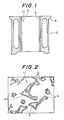
- Fig. 1 is a cross sectional view of a bore portion of a cylinder block 1 made of an aluminum alloy prepared as described above, in which a cylinder bore 2 is strengthened by a porous metal 3.
- the cylinder bore 2 in which a piston (not illustrated) is reciprocated to cause wear or scuffing, can be strengthened by the porous metal 3.
- the composition to strengthen the bore 2 can be performed simultaneously with the manufacture of the cylinder block 1, and only the bore 2 in which wear resistance is required can be constituted with the porous metal 3 while most of other portions may be constituted with an aluminum alloy 4. Accordingly, it can be manufactured easily and the material cost is not too expensive. In this case, since the squeeze casting method is used, strength of the aluminum alloy is improved and the casting defects are decreased.
- FIG. 2 is an enlarged view for the metal structure of the cylinder bore surface 11.
- dotted areas show a region of the porous metal 3
- blank areas show a region of the aluminum alloy 4 as a matrix. It can be seen, on the surface 11 of the aluminum alloy matrix composite, that the porous metal 3 is present like islands in the aluminum alloy 4 and the aluminum alloy 4 is like a small island in a relatively large porous metal 3.
- Lapping treatment is performed on the cylinder bore surface 11 by applying a lapping agent to the cylinder bore surface 11, the lapping agent generally consisting of a slurry which is prepared from a suspension of hard fine particles such as SiC in liquid such as oil.
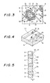
- Fig. 3 and Fig. 4 show an enlarged view for a portion of the surface 11 and an enlarged perspective view for a portion after the lapping, respectively.
- pits 13 and grooves 14 are formed preferentially in the region of the aluminum alloy 4, because the composite material comprises heterogenous phases each having different hardness, i.e., the porous metal 3 and the aluminum alloy 4, and the hardness of the region of the aluminum alloy is smaller than that of the region of the porous metal 3.
- the Vickers hardness of the porous metal consisting of nickel diffused with chromium by more than 20 weight % is about from 250 to 300 (as measured by micro Vickers hardness tester), while the Brinell hardness of the aluminum alloy, for example, AC8A specified by JIS is about 100 (about 115 when converted as Vickers hardness).
- a lapping shoe made of cast iron FC15 as specified in JIS is pressed and slid against the bore surface 11 at a pressure of 0.2 kg/cm2 under the conditions of 100 rpm of rotation and 100 mm strokes.
- a lapping agent of a slurry in which Si particles of about 400 mesh are mixed in a lubricant having 1200 cs of viscosity is dropped between the surface of the shoe and the bore surface 11.
- Si particles are rolled at the surface 11 and rub the surface 11
- a portion of the region of the aluminum alloy 4 is scratched to form pits 13 each having 1 to 10 ⁇ m depth.
- the surface 11 is slightly polished by means of a shoe made of cork or rubber to eliminate burrs which have been formed at the periphery of the aluminum alloy, thereby to form pits 13 each having 1 to 4 ⁇ m depth, the pits being dispersed uniformly in the region of the aluminum alloy 4.
- the surface 11 is scratched with SiC particles in one direction over a relatively long distance, thereby to form grooves 14.
- the pressure of the shoe is within a range of 0.05 to 1.0 kg/cm2, for forming the pits 13 and/or grooves 14 preferentially to the region of the aluminum alloy 4.
- a pressure greater than 1.0 kg/cm2 is not desired since many pits or grooves are also formed in the region of the porous metal 3.
- Fig. 5 shows a cross sectional view of the thus lapped surface 11.
- the region of the aluminum alloy 4 is scratched a little more than the region of the porous metal 3
- the region of the aluminum alloy 4 is entirely concaved on the surface 11 shown in Fig. 2 to form a recess 12 and the region of the porous metal 3 is relatively protruded.
- the pits 13 and the grooves 14 are left at the surface of the region of the aluminum alloy 4 in the recess 12.
- the recess 12 has a depth d of about 0.2 to 2.0 ⁇ m.
- lubricant forms oil films between the bore surface 11 and the surface of the piston.
- the lubricant can be effectively stored in the recesses 12, pits 13 and the groove 14, which have the function of oil pockets to maintain the oil films satisfactorily. As a result, lubricancy and scuffing resistance can be improved in the gaps.
- the region of the aluminum alloy 4 is entirely concaved as shown in Fig. 5, and it is more preferred that the pits 13 and/or grooves 14 are present in the recess 12 because the effect of storing the lubricant is further improved.
- the hard particles of 200 to 800 mesh are preferably used for the lapping. Coarse particles greater than 200 mesh are not preferred since the depth and the size of the pit or the groove are too great, which increases the consumption amount of the lubricant. Fine particles of less than 800 mesh are not preferred since the performance of forming pits or grooves is reduced.
- SiC particles 17 of hard grains are slightly embedded as small lumps into the aluminum alloy 4 as shown in Figs. 3 and 4 upon lapping, as the size of the hard particles is larger, abrasion given to the piston (opposite sliding member) is increased.
- the pressure of the shoe in the lapping is preferably less than 1.0 kg/cm2 since the amount of the embedded hard particles is reduced as the shoe pressure is lower.
- the hard particles having 400 to 800 mesh are particularly preferred for the same reasons as described above.
- the porous metal sheet After compressing a sheet material of 5 mm thickness made of a raw porous metal comprising nickel (Ni Cermet #6, manufactured by Sumitomo Denko) in one direction into 3 mm thickness, the porous metal sheet was molded into a cylindrical shape of about 100 mm inner diameter. Then, chromium was diffused into the cylindrical porous metal by chroming to have a content of 35 weight %.
- the cylindrical porous metal body was set to a die in which a molten aluminum alloy (Al-Si-Cu-Ni-Mg series alloy) AC8A (Cu: 0.8 to 1.3 wt.%, Si: 11.0 to 13.0 wt.%, Mg: 0.7 to 1.3 wt.% and Ni: 0.8 to 1.5 wt.%) as specified according to JIS was poured at a temperature of 760°C and under a pressure of 700 kg/cm2 to prepare a hollow cylindrical aluminum alloy matrix composite with the volume ratio of the porous metal of about 10 volume %. After applying so-called T6 treatment specified by JIS to the hollow cylindrical body, slight grinding treatment was applied to the inner surface of the hollow cylindrical body.
- a molten aluminum alloy Al-Si-Cu-Ni-Mg series alloy
- AC8A Cu: 0.8 to 1.3 wt.%, Si: 11.0 to 13.0 wt.%, Mg: 0.7 to 1.3 wt.% and Ni: 0.8
- the hollow cylindrical body was set to a lapping device, and a shoe made of an extremely soft cast iron (F15C specified by JIS) was pressed to the inner surface of the hollow cylindrical body under a pressure adjusted to 0.12 kg/mm2 while applying a tapping agent constituting of a slurry in which SiC particles of 600 mesh were mixed into a lubricant having 1200 cs of viscosity. Then, lapping was applied for 2 minutes under the conditions of 100 rpm of rotation and 100 mm of stroke.
- F15C specified by JIS extremely soft cast iron
- the shoe was replaced with one made of rubber and a lapping finishing was performed (without using the lapping agent) under a pressure of 0.2 kg/cm2 for 30 sec., whereby recess 12 each having about 0.2 to 0.5 ⁇ m depth were formed over the entire regions of aluminum alloy 4 mainly, and a number of pits 13 and grooves 14 each having 2 to 3 ⁇ m depth were formed at the surface of the recess 12.
- a hollow cylindrical body of the same shape as that in Example 1 was prepared by using cast iron having flaky graphite (C: 3.1 wt.%, B: 0.06 wt.%, Si: 2.0 wt.%, Mn: 0.7 wt.%, P: 0.3 wt.%, Fe: balance), and plateau honing was applied to the inner surface to a roughness of 2 to 3 ⁇ m.
- a hollow cylindrical body of the same shape as that in Example 1 was prepared by casting with an aluminum alloy (Si:17 wt.%, Cu: 4.5 wt.%, Mg: 0.5 wt.%, Al: balance) such that Si primary crystals of 50 to 70 ⁇ m were uniformly dispersed. After applying T6 treatment to the hollow cylindrical body, slight grinding was applied to the inner surface of the hollow cylindrical body. Then, the surface was finished by honing to a roughness of less then 0.5 ⁇ m. Subsequently, the inner surface was electrolytically etched in a solution of sodium nitrate, by which Si particles were embossed about 1 ⁇ m from the inner surface.
- an aluminum alloy Si:17 wt.%, Cu: 4.5 wt.%, Mg: 0.5 wt.%, Al: balance
- a hollow cylindrical body of the same shape as that in Example 1 was prepared by penetrating a molten aluminum alloy AC8A at a temperature of 760°C under a pressure of 800 kg/cm into a cylindrical molding body of Al2O3-SiO2 fibers (Al2O3 : 50%, volume ratio Vf: 9%, shot: less than 1%, manufactured by Nichias Co.). After applying T6 treatment to the hollow cylindrical body, slight grinding was applied to the inner surface of the hollow cylindrical body. Then, the surface was finished by honing to less than 1 ⁇ m roughness. Then, electrolytic etching was applied to the inner surface such that the portions of the aluminum alloy between the fibers the formed recesses of each having 2 ⁇ m depth.
- Si particles less than 3 ⁇ m were dispersed in Ni at about 3 weight % and Ni dispersion plating was applied to form a thickness of about 70 ⁇ m on the inner surface of a hollow cylindrical body made of an aluminum alloy AC8A (the same shape as in Example 1). Then, the inner surface was finished by honing to a surface roughness of 1 to 2 ⁇ m.
- Example 2 the same hollow cylindrical body was prepared under the same conditions and applied with the same treatment as those in Example 1 except for replacing the aluminum alloy in Example 1 with AC9B as specified by JIS.
- Test pieces were cut out from each of the hollow cylindrical bodies in Examples 1, 2 and Comparative Examples 1 to 4 described above, and a wear test was carried out for the test specimens by using an Ohgoshi type Wear Tester.
- the rotor of the tester having the surface to be in sliding contact with the test specimen was made of the same cast iron as in Comparative Example 1. Pressed indents were formed by a pyramid shaped weight to the circumferential sliding surface of the rotor to be in sliding contact with the test specimen.
- the abrasion amount of the rotor itself was also measured by microscopically measuring the length of the diagonal line of the indent before and after the wear test.
- the test conditions for the wear test were 570 m of friction distance, 0.12 m/sec. of friction speed, 1.9 kg of load, 3 cc/min. of the amount of dropping lubricant (SAECC grade #30).
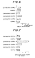
- Fig. 6 and Fig. 7 show the results of the wear test for examples 1, 2 and Comparative Examples 1 to 4.
- Fig. 6 shows the specific wear amount for each of the test specimens
- Fig. 7 shows the wear amount of the rotor measured in the wear resistance test for each of the test specimens, and normalized by the wear amount of the rotor measured in Comparative Example 1. From Figure 7, it can be seen the degree of injury given from each of the members in Examples 1, 2 and Comparative Examples 1 to 4 to the opposite sliding material. From Figs. 6 and 7, it can be seen that the specific wear amount was least in Comparative Example 3 (aluminum alloy strengthened by composing with Al2O3-SiO2 fibers) but greatest injury was given to the mating sliding member, because the fibers are extremely hard.
- Comparative Example 3 aluminum alloy strengthened by composing with Al2O3-SiO2 fibers
- Example 1 shows wear resistance as comparable with that in Comparative example 1 (cast iron material) and Comparative Example 4 (Ni-dispersion placed material), which were actually used so far with satisfactory results and that the material in Example 1 was further improved with the wear resistance as compared with the material in Example 1.
- oil pockets are formed by etching on the inner surface of the cylinder bore comprising the aluminum alloy matrix composite as described in the first embodiment.
- Etching is applied to the cylinder bore surface 11 shown in Fig. 2. Impurities are present in the region of the aluminum alloy 4 to form a phase which is different from the matrix phase of aluminum alloy.
- the etching is adapted to selectively etch the objective phase.
- the etching method can generally be classified into a following three types depending on the phases to be etched:
- an etching treatment is selected so as to etch the aluminum alloy 4 in preference to the chromium-containing porous metal 3.
- Such etching includes a chemical etching treatment using an NaOH solution or a mixed solution of H3PO4 and H2SO4.
- an etching treatment is selected so as to dissolve preferentially the phase of impurities, for example, Mg2Si in the aluminum alloy 4.
- Such etching includes a chemical etching treatment using an HNO3 solution, Cr2O3 solution or CrO3 solution.
- the method (b) is preferably applied after applying the method (a).
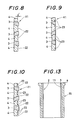
- Figs. 8 to 10 are cross sectional views for the cylinder bore surface 11 obtained by applying etching as described above.
- Fig. 8 shows the surface 11 after applying the method (a) above, in which the region of the aluminum alloy 4 is etched more than the region of the porous metal 3.
- the region of the aluminum alloy 4 is entirely concaved to form a recess 22, while the region of the porous metal 3 is relatively protruded.
- the depth d′ of the recess 22 is 1 to 4 ⁇ m.
- a desired depth d′ can be formed in the recess 22 by properly setting etching conditions (etching solution, etching time, concentration, etc.).
- Oil films are formed with a lubricant between the bore surface 11 and a piston so as to smooth the reciprocal movement of the piston in the cylinder bore 2, and the lubricant can be effectively stored in the recess 22 thus formed in the bore surface 11. Since the recess 22 has the function of oil pockets thereby maintaining the oil films satisfactorily, lubricancy and scuffing resistance can be improved in the gap. If the depth d′ of the recess 12 is excessively great, it is not preferred since the consumption amount of the lubricant is increased. Accordingly, the depth d′ for the recess 22 is preferably about from 0.3 to 5 ⁇ m.
- Fig. 9 shows the cylinder bore surface after applying the method (b) above, in which fine pits 13 are formed by dissolving impurities such as MgSi in the region of the aluminum alloy 4.
- impurities such as MgSi
- aqueous solution containing 20 weight % of HNO impurities in the aluminum alloy 3 can be removed by dissolving to form a lot of fine pits 23. Since a great number of impurities are present in the aluminum alloy 4, a number of pits 23 are formed.
- the depth d′ of the pit is about 1 to 8 ⁇ m, which will depend on the size of the impurities.
- the pits 23 have also the function as the oil pockets for the lubricant.
- Fig. 10 shows the cylinder bore surface 11 after applying the method (c) above, in which a recess 22 is formed to the surface 11 and, subsequently, the pits 23 are formed on the surface of the region of the recess 22 of the aluminum alloy 4. Formation of both of the recess 22 and the pits 23 on the surface 11 are preferred since the effect as oil pockets for the storing the lubricant is further increased.
- electrolytic etching may also be used.
- the porous metal sheet After compressing a sheet material of 5 mm thickness made of a raw porous metal comprising nickel (Ni Cermet #6, manufactured by Sumitomo Denko) in one directions into 3 mm thickness, the porous metal sheet was molded into a cylindrical shape of about 100 mm inner diameter. Then, chromium was diffused into the cylindrical porous metal by chroming to be a content of 35 weight %.
- the cylindrical porous metal body was set to a die in which a molten aluminum alloy AC8A as specified according to JIS was poured at a temperature of 760°C and under a pressure of 700 kg/cm2 to form a hollow cylindrical aluminum alloy matrix composite with the volume ratio of the porous metal about 10 volume %.
- a so-called T6 treatment as specified by JIS was applied to the hollow cylindrical body.
- the surface was finished by honing.
- etching to the inner surface such that it was immersed for 2 min. in an aqueous solution containing 10 weight % of NaOH, recesses 22 each having 0.5 to 1.5 ⁇ m depth d′ were formed on the inner surface.
- Example 4 the same hollow cylindrical body was prepared under the same conditions and applied with same treatment as those in Example 3 except for replacing the aluminum alloy in Example 3 with AC9B specified by JIS.
- Test pieces were cut out from each of the hollow cylindrical bodies in Examples 3 and 4, and a wear test was carried out for the test specimens in the same methods as those in Examples 1, 2 by an Ohgoshi type wear tester.
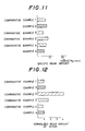
- Figs. 11 and 12 show the results of the wear test for Examples 3 and 4 in comparison with the results of Comparative Examples 1 to 4.
- Fig. 11 shows a specific wear amount for each of the test specimens and Fig. 12 shows the normalized wear amount of the rotor measured in the wear tester for each of the test specimens by being normalized with the wear amount of the rotor measured in Comparative Example 1.
- Fig. 13 shows an application example in which the aluminum alloy matrix composite according to the present invention is applied to a cylinder liner 15.
- the cylinder liner 15 is made of an aluminum alloy 4 composed with a cylindrically shaped porous metal 3 by the method as described above.
- the inner surface 11 constitutes the cylinder bore 2, and by applying the same fabrication as that described above, recesses 12, 22 and/or pits 13/23 are formed as oil pits on the inner surface 11.
- the cylinder liner 15 is fit into the cylinder bore and then secured by means of shrinkage fit or expansion fit. Since the cylinder block for the internal combustion engine can be manufactured with a cylinder liner 15 by an inexpensive casting method such as low pressure casting or die casting without the process such as plating, production cost can be reduced. If the aluminum alloy composite is made of an aluminum alloy of high Si content, the wear resistance of the cylinder liner 15 can further be improved.
- the aluminum alloy matrix composite for internal combustion engines according to the present invention can provide the advantages as described below:
Landscapes
- Engineering & Computer Science (AREA)
- Chemical & Material Sciences (AREA)
- Mechanical Engineering (AREA)
- Materials Engineering (AREA)
- Combustion & Propulsion (AREA)
- General Engineering & Computer Science (AREA)
- Manufacturing & Machinery (AREA)
- Metallurgy (AREA)
- Organic Chemistry (AREA)
- Composite Materials (AREA)
- Cylinder Crankcases Of Internal Combustion Engines (AREA)
Abstract
Description
- The present invention relates to an aluminum alloy matrix composite for internal combustion engines, comprising a porous metal composed with an aluminum alloy, which is suitable to be used for sliding portions in internal combustion engines.
- A cylinder block made of an aluminum alloy for internal combustion engines has many advantages such that the weight of the engine can be reduced remarkably as compared with a cylinder block, for example, made of cast iron, it has good heat dissipation, and noises can be decreased by reducing a gap between the cylinder block and a piston made of aluminum alloy. Accordingly, use of cylinder blocks made of aluminum alloy have been increased more and more.
- A bore in a cylinder made of an aluminum alloy in which a piston is reciprocated has been strengthened to improve of the wear resistance, generally, by the following three methods:
- (1) improvement for the aluminum alloy itself,
- (2) surface treatment applied to the bore of the cylinder,
- (3) composite strengthening for the aluminum alloy with ceramic fibers or particles.
- However, each of the foregoing methods involve the following drawbacks.
- A typical example for (1) above is an aluminum alloy A390 of high Si content available from Reynolds Co., which is widely used mainly in Europe. In this alloy, the wear resistance is improved by floating hard primary crystals of Si particles, but the high Si aluminum alloy has poor castability and poor machinability, which leads to increase the production cost.
- Further, there has also been proposed an alloy comprising aluminum alloy and graphite particles dispensed therein for the improvement of the lubricancy. Since the mechanical strength is reduced in this alloy due to mixing of graphite, it has been studied for the practical application of the alloy to use it only as a liner in the cylinder bore. The alloy is produced by a casting method or an extrusion method. In the casting method, since the surface of the graphite particles is treated by Ni plating or the like in advance in order to suppress the reaction between graphite and a molten aluminum alloy during casting, it increases the production cost. It is often difficult for the method to perform casting with uniform dispersion of the graphite particles. In the extrusion method, an aluminum powder and a graphite powder are extruded and sintered, but this method has not yet been put to practical use since it involves a problem that the graphite is extended in the extruding direction to deteriorate the wear resistance.
- The surface treatment as described in (2) above includes Cr plating, or Ni dispersion plating in which hard fine particles such as SiC or TiB are dispensed in Ni plating. It is often used for cylinders made of aluminum alloy in 2-cycle engines. However, when applying the surface treatment to a large cylinder block such as in 4-cycle gasolin engines, the cylinder block has to be dipped into a plating bath after the portions other than those applied with plating are masked. Since the masking operation is difficult and increases the cost, this is not suitable to mass production.
- The typical example of the method of composite strengthening for the aluminum alloy as described in (3) above, is a method of strengthening with inorganic fibers such as Al₂O₃ fibers, or a method of strengthening by dispersing inorganic particles such as silicon nitride into a molten aluminum alloy and then applying die casting (Japanese Patent Application No. 149166/1985). However, since fine and hard inorganic fibers or particles are present in the aluminum alloy cylinder which is strengthened by the above-mentioned method, they cause abrasion to a piston ring or a piston during use, therefore, the method has not yet been put to practical use. In addition, Japanese Patent Applications No. 102802/1986, No. 141130/1986 and No. 38542/1988 propose the use of a combination of Al₂O₃-SiO₂ fibers or Al₂O₃ fibers and C fibers as the strengthening material and the protection to the opposite sliding portions with plating or flame spraying in order to improve the wear resistance and the scuffing resistance. In a case of an aluminum alloy composite material using hard composite strengthening material such as inorganic fibers, since the hard fibers which are scatteringly protruded in the aluminum alloy composite material scratch the opposite sliding members to cause abrasion, both of the members have to be selected and combined, taking the properties of the opposite members to each other into consideration.
- The object of the present invention is to provide an aluminum alloy matrix composite for internal combustion engines capable of preventing injuries such as abrasion to opposite sliding members and capable of improving the wear resistance and the scuffing resistance of the composite.
- In order to achieve said object of the present invention, there is provided an aluminum alloy matrix composite for internal combustion engines, which is strengthened by a porous metal; and in an exposed surface of which at least a part of the aluminum alloy is scratched a little more than parts of the porous metal by lapping so that fine oil pockets are formed in the exposed surface, the porous metal containing chromium of 10 to 55 weight %, preferably 15 to 55 weight %, and the volumetric ratio of the porous metal being within a range of 6 to 30 volume %, preferably 8 to 20 volume %.
- According to another feature of the present invention, there is provided an aluminum alloy matrix composite for internal combustion engines, which is strengthened by a porous metal; and in an exposed surface of which at least a part of the aluminum alloy is removed a little more than parts of the porous metal by etching so that fine oil pockets are formed in the exposed surface, the porous metal containing chromium of 10 to 55 weight %, preferably 15 to 55 weight %, and the volumetric ratio of the porous metal being within a range of 6 to 30 volume %, preferably 8 to 20 volume %.
- The porous metal is preferably obtained by compressing a raw porous metal in one direction, the raw porous metal having 85 to 98 volume % in porosity.
- The porous metal is preferably embedded in the aluminum alloy mainly by means of squeeze casting.
- The porous metal as the composite strengthening material preferably comprises material, preferably iron or nickel harder than the aluminum alloy.
- The aluminum alloy is, preferably, Al-Cu series alloy, Al-Cu-Si series alloy, Al-Si series alloy, Al-Si-Mg series alloy, Al-Si-Cu series alloy, Al-Si-Cu-Mg series alloy, Al-Cu-Ni-Mg series alloy, Al-Mg series alloy or Al-Si-Cu-Ni-Mg series alloy.
- Since the aluminum alloy is composed with the porous metal, it is possible to apply composite strengthening only for a required portion by forming the porous metal into an objective shape.
- If the volumetric ratio of the porous metal is less than 6 volume %, since the ratio of the composite strengthening material in the aluminum alloy matrix composite is reduced, the effect of improving the wear resistance of the composite member is reduced. On the contrary, if the volumetric ratio is more than 30 volume %, penetrating property of the aluminum alloy into the porous metal is reduced upon composition.
- The chromium content necessary for the porous metal is within a range of 10 to 55 weight %. The formation of brittle intermetallic compounds can be suppressed upon composition of the aluminum alloy and the porous metal thereby increasing the strength at the boundary between the aluminum alloy and the porous metal if the chromium content is more than 10 weight %. If the brittle intermetallic compound is formed, cracks may possibly occur at the portion of the intermetallic compound. Further, in the porous metal the hardness is increased by containing chromium, thereby improving the wear resistance of the composite portion. However, if chromium content is more than 55 weight %, the wear resistance is not improved so much. Since the hardness is lower than that of the inorganic fibers or particles, there is no possibility of damage to the opposite sliding portion or the like.
- The porous metal and the aluminum alloy are exposed in the surface of the aluminum alloy matrix composite strengthened by the porous metal. Since the aluminum alloy is softer than the porous metal containing chromium, at least a part of a region of the aluminum alloy is scratched a little more than parts of the porous metal by lapping, thereby forming fine recesses, pits or grooves.
- Alternatively, at least a part of a region of the aluminum alloy is removed a little more than parts of the porous metal by etching, thereby forming fine recesses or pits.
- Since the recesses, pits or grooves constitute oil pockets for the lubricant used in an internal combustion engine, it is possible to effectively store the lubricant on the surface.
- Reference will now be made, by way of example, to the accompanying drawings in which:
- Fig. 1 is a vertical cross sectional view for a bore portion of a cylinder block for internal combustion engines made of an aluminum alloy matrix composite according to the present invention;
- Fig. 2 is an enlarged plan view of a portion of the surface of a cylinder bore portion constituted with the aluminum alloy matrix composite;
- Fig. 3 is an enlarged plan view of a portion illustrating pits and grooves formed as oil pockets by lapping on the surface of the cylinder bore portion shown in Fig. 2;
- Fig. 4 is an enlarged perspective view of a portion illustrating pits and grooves formed as oil pockets;
- Fig. 5 is a cross sectional view illustrating recesses, pits and grooves formed as oil pockets;
- Fig. 6 is a graph illustrating the specific wear amount for each of the materials in Examples 1, 2 and Comparative examples 1 to 4 measured by the wear test;
- Fig. 7 is a graph illustrating the normalized wear amount by that measured in Comparative Example 1 for each rotor portions of the wear tester, said each rotor portions being used for each of the materials in Examples 1, 2 and Comparative Examples 1 to 4 upon the wear test;
- Fig. 8 is a cross sectional view illustrating recesses formed as oil pockets by etching on the surface of the cylinder bore shown in Fig. 2;
- Fig. 9 is a cross sectional view illustrating pits formed as oil pockets;
- Fig. 10 is a cross sectional view illustrating recesses and pits formed as oil pockets;
- Fig. 11 is a graph illustrating the specific wear amount for each of the materials in Examples 3, 4 and Comparative Examples 1 to 4 measured by a wear test;
- Fig. 12 is a view illustrating the normalized wear amount by that measured in Comparative Example 1 for each of the rotor portions of the wear tester, said each of rotor portions being used for each of the materials in Examples 3, 4 and Comparative Examples 1 to 4 upon the wear test; and
- Fig. 13 is a vertical cross sectional view of a cylinder liner in a example for application.
- The present invention will now be explained by way of preferred embodiments with reference to the drawings, with the understanding that the present disclosure is not intended to limit the invention to the embodiments.
- In a first embodiment, a cylinder bore, in which the wear resistance and the scuffing resistance in the cylinder body of an internal combustion engine are required, is constituted with an aluminum alloy matrix composite according to the present invention.
- At first, as previously proposed by the present inventors in Japanese Patent Application No. 149220/1989, a plate-like raw porous metal with 85 to 98 volume % in porosity is compressed preferentially in one direction into a porous metal sheet with 6 to 30 volume %, preferably, 8 to 20 volume % of volumetric ratio Vf. The porous metal has the function of strengthening material in the composite material. The wear resistance of the composite material is improved as much as the increased volumetric ratio of the porous metal by compressing the raw porous metal. If the volumetric ratio of the porous metal is less than 6 volume %, there is less effect for improving the wear resistance. On the other hand, if it exceeds 30 volume %, the porous metal is not easily composited with the aluminum alloy. When the porous metal is compressed preferentially in one direction, the diameter of the pores in the porous metal observed in the direction of the compression does not substantially change as compared with the diameter before compression. Accordingly, the penetrability of the molten aluminum alloy into the porous metal does not substantially change as compared with that of using the raw porous metal. A method of uniform compression of the raw porous metal with hydrostatic pressure is not preferred since the volumetric ratio is increased. Since the porous metal is preferably harder than the aluminum alloy in view of wear resistance, the porous metal consists of iron, nickel or the like.
- The porous metal sheet is molded into a cylindrical shape so as to form a cylinder bore, then chromium is diffused into the cylindrical porous metal to a content from 10 to 55 weight %.
- When porous metal of iron or nickel is brought into reaction with aluminum upon composition, brittle intermetallic compounds are formed at the boundary between them. When the composited aluminum alloy material is used, for example, in a piston of an internal combustion engine, the piston undergoes thermal cycles of heating and cooling for a long period of time, and cracks may possibly occur at the portion of the brittle intermetallic compounds. The present inventors have disclosed in Japanese Patent Application No. 222239/1988 that the formation of the brittle intermetallic compound can be suppressed by using a porous metal whose surface is treated by chroming or the like to depth of 0.001 mm or more so that the porous metal contains more than 10 weight %, preferably, more than 15 weight % chromium. By containing upto 55 weight % chromium the hardness of the porous metal can be increased to improve the wear resistance of the porous metal.
- The cylindrical porous metal body is set to a die for casting a cylinder block. Then, when the cylinder block is casted by squeeze casting, a molten aluminum alloy is penetrates into the porous metal.
- Fig. 1 is a cross sectional view of a bore portion of a
cylinder block 1 made of an aluminum alloy prepared as described above, in which acylinder bore 2 is strengthened by aporous metal 3. When thecylinder block 1 is thus manufactured, the cylinder bore 2, in which a piston (not illustrated) is reciprocated to cause wear or scuffing, can be strengthened by theporous metal 3. In addition, the composition to strengthen thebore 2 can be performed simultaneously with the manufacture of thecylinder block 1, and only thebore 2 in which wear resistance is required can be constituted with theporous metal 3 while most of other portions may be constituted with analuminum alloy 4. Accordingly, it can be manufactured easily and the material cost is not too expensive. In this case, since the squeeze casting method is used, strength of the aluminum alloy is improved and the casting defects are decreased. - A surface finishing is applied to the
cylinder bore 2. Fig. 2 is an enlarged view for the metal structure of the cylinder boresurface 11. In Fig. 2, dotted areas show a region of theporous metal 3, and blank areas show a region of thealuminum alloy 4 as a matrix. It can be seen, on thesurface 11 of the aluminum alloy matrix composite, that theporous metal 3 is present like islands in thealuminum alloy 4 and thealuminum alloy 4 is like a small island in a relatively largeporous metal 3. - Lapping treatment is performed on the cylinder bore
surface 11 by applying a lapping agent to the cylinder boresurface 11, the lapping agent generally consisting of a slurry which is prepared from a suspension of hard fine particles such as SiC in liquid such as oil. Fig. 3 and Fig. 4 show an enlarged view for a portion of thesurface 11 and an enlarged perspective view for a portion after the lapping, respectively. As shown in Figs. 3 and 4, pits 13 andgrooves 14 are formed preferentially in the region of thealuminum alloy 4, because the composite material comprises heterogenous phases each having different hardness, i.e., theporous metal 3 and thealuminum alloy 4, and the hardness of the region of the aluminum alloy is smaller than that of the region of theporous metal 3. That is, the Vickers hardness of the porous metal consisting of nickel diffused with chromium by more than 20 weight % is about from 250 to 300 (as measured by micro Vickers hardness tester), while the Brinell hardness of the aluminum alloy, for example, AC8A specified by JIS is about 100 (about 115 when converted as Vickers hardness). A lapping shoe made of cast iron FC15 as specified in JIS is pressed and slid against thebore surface 11 at a pressure of 0.2 kg/cm² under the conditions of 100 rpm of rotation and 100 mm strokes. At the same time, a lapping agent of a slurry in which Si particles of about 400 mesh are mixed in a lubricant having 1200 cs of viscosity is dropped between the surface of the shoe and thebore surface 11. When the Si particles are rolled at thesurface 11 and rub thesurface 11, a portion of the region of thealuminum alloy 4 is scratched to formpits 13 each having 1 to 10 µm depth. Subsequently, thesurface 11 is slightly polished by means of a shoe made of cork or rubber to eliminate burrs which have been formed at the periphery of the aluminum alloy, thereby to formpits 13 each having 1 to 4 µm depth, the pits being dispersed uniformly in the region of thealuminum alloy 4. At the same time, thesurface 11 is scratched with SiC particles in one direction over a relatively long distance, thereby to formgrooves 14. - While the above-mentioned lapping conditions can be varied appropriately, it is desirable that the pressure of the shoe is within a range of 0.05 to 1.0 kg/cm², for forming the
pits 13 and/orgrooves 14 preferentially to the region of thealuminum alloy 4. A pressure greater than 1.0 kg/cm² is not desired since many pits or grooves are also formed in the region of theporous metal 3. - If lapping is applied for a relatively long period of time (about 0.5 to 3 minutes) under a relatively low shoe pressure, the region of the
aluminum alloy 4 is entirely concaved by scratching. Fig. 5 shows a cross sectional view of the thus lappedsurface 11. As shown in Fig. 5, since the region of thealuminum alloy 4 is scratched a little more than the region of theporous metal 3, the region of thealuminum alloy 4 is entirely concaved on thesurface 11 shown in Fig. 2 to form arecess 12 and the region of theporous metal 3 is relatively protruded. Thepits 13 and thegrooves 14 are left at the surface of the region of thealuminum alloy 4 in therecess 12. Therecess 12 has a depth d of about 0.2 to 2.0 µm. - For smoothing the reciprocal movement of the piston in the cylinder bore 2, lubricant forms oil films between the
bore surface 11 and the surface of the piston. The lubricant can be effectively stored in therecesses 12, pits 13 and thegroove 14, which have the function of oil pockets to maintain the oil films satisfactorily. As a result, lubricancy and scuffing resistance can be improved in the gaps. - In particular, when the composite material of the
aluminum alloy 4 and theporous metal 3 is used for the cylinder bore, since scuffing occurs in the regions of thesoft aluminum alloy 4, it is preferred that the region of thealuminum alloy 4 is entirely concaved as shown in Fig. 5, and it is more preferred that thepits 13 and/orgrooves 14 are present in therecess 12 because the effect of storing the lubricant is further improved. - The hard particles of 200 to 800 mesh are preferably used for the lapping. Coarse particles greater than 200 mesh are not preferred since the depth and the size of the pit or the groove are too great, which increases the consumption amount of the lubricant. Fine particles of less than 800 mesh are not preferred since the performance of forming pits or grooves is reduced. In the case that
SiC particles 17 of hard grains are slightly embedded as small lumps into thealuminum alloy 4 as shown in Figs. 3 and 4 upon lapping, as the size of the hard particles is larger, abrasion given to the piston (opposite sliding member) is increased. In addition, the pressure of the shoe in the lapping is preferably less than 1.0 kg/cm² since the amount of the embedded hard particles is reduced as the shoe pressure is lower. The hard particles having 400 to 800 mesh are particularly preferred for the same reasons as described above. - The aluminum alloy matrix composite in the first embodiment will now be explained referring to Examples 1, 2 and Comparative Examples 1 to 4.
- After compressing a sheet material of 5 mm thickness made of a raw porous metal comprising nickel (Ni Cermet #6, manufactured by Sumitomo Denko) in one direction into 3 mm thickness, the porous metal sheet was molded into a cylindrical shape of about 100 mm inner diameter. Then, chromium was diffused into the cylindrical porous metal by chroming to have a content of 35 weight %.
- Then, the cylindrical porous metal body was set to a die in which a molten aluminum alloy (Al-Si-Cu-Ni-Mg series alloy) AC8A (Cu: 0.8 to 1.3 wt.%, Si: 11.0 to 13.0 wt.%, Mg: 0.7 to 1.3 wt.% and Ni: 0.8 to 1.5 wt.%) as specified according to JIS was poured at a temperature of 760°C and under a pressure of 700 kg/cm² to prepare a hollow cylindrical aluminum alloy matrix composite with the volume ratio of the porous metal of about 10 volume %. After applying so-called T6 treatment specified by JIS to the hollow cylindrical body, slight grinding treatment was applied to the inner surface of the hollow cylindrical body. Subsequently, the hollow cylindrical body was set to a lapping device, and a shoe made of an extremely soft cast iron (F15C specified by JIS) was pressed to the inner surface of the hollow cylindrical body under a pressure adjusted to 0.12 kg/mm² while applying a tapping agent constituting of a slurry in which SiC particles of 600 mesh were mixed into a lubricant having 1200 cs of viscosity. Then, lapping was applied for 2 minutes under the conditions of 100 rpm of rotation and 100 mm of stroke. Successively, the shoe was replaced with one made of rubber and a lapping finishing was performed (without using the lapping agent) under a pressure of 0.2 kg/cm² for 30 sec., whereby
recess 12 each having about 0.2 to 0.5 µm depth were formed over the entire regions ofaluminum alloy 4 mainly, and a number ofpits 13 andgrooves 14 each having 2 to 3 µm depth were formed at the surface of therecess 12. - A hollow cylindrical body of the same shape as that in Example 1 was prepared by using cast iron having flaky graphite (C: 3.1 wt.%, B: 0.06 wt.%, Si: 2.0 wt.%, Mn: 0.7 wt.%, P: 0.3 wt.%, Fe: balance), and plateau honing was applied to the inner surface to a roughness of 2 to 3 µm.
- A hollow cylindrical body of the same shape as that in Example 1 was prepared by casting with an aluminum alloy (Si:17 wt.%, Cu: 4.5 wt.%, Mg: 0.5 wt.%, Al: balance) such that Si primary crystals of 50 to 70 µm were uniformly dispersed. After applying T6 treatment to the hollow cylindrical body, slight grinding was applied to the inner surface of the hollow cylindrical body. Then, the surface was finished by honing to a roughness of less then 0.5 µm. Subsequently, the inner surface was electrolytically etched in a solution of sodium nitrate, by which Si particles were embossed about 1 µm from the inner surface.
- A hollow cylindrical body of the same shape as that in Example 1 was prepared by penetrating a molten aluminum alloy AC8A at a temperature of 760°C under a pressure of 800 kg/cm into a cylindrical molding body of Al₂O₃-SiO₂ fibers (Al₂O₃ : 50%, volume ratio Vf: 9%, shot: less than 1%, manufactured by Nichias Co.). After applying T6 treatment to the hollow cylindrical body, slight grinding was applied to the inner surface of the hollow cylindrical body. Then, the surface was finished by honing to less than 1 µm roughness. Then, electrolytic etching was applied to the inner surface such that the portions of the aluminum alloy between the fibers the formed recesses of each having 2 µm depth.
- Si particles less than 3 µm were dispersed in Ni at about 3 weight % and Ni dispersion plating was applied to form a thickness of about 70 µm on the inner surface of a hollow cylindrical body made of an aluminum alloy AC8A (the same shape as in Example 1). Then, the inner surface was finished by honing to a surface roughness of 1 to 2µm.
- In this Example 2, the same hollow cylindrical body was prepared under the same conditions and applied with the same treatment as those in Example 1 except for replacing the aluminum alloy in Example 1 with AC9B as specified by JIS.
- Test pieces were cut out from each of the hollow cylindrical bodies in Examples 1, 2 and Comparative Examples 1 to 4 described above, and a wear test was carried out for the test specimens by using an Ohgoshi type Wear Tester. The rotor of the tester having the surface to be in sliding contact with the test specimen was made of the same cast iron as in Comparative Example 1. Pressed indents were formed by a pyramid shaped weight to the circumferential sliding surface of the rotor to be in sliding contact with the test specimen. The abrasion amount of the rotor itself was also measured by microscopically measuring the length of the diagonal line of the indent before and after the wear test. The test conditions for the wear test were 570 m of friction distance, 0.12 m/sec. of friction speed, 1.9 kg of load, 3 cc/min. of the amount of dropping lubricant (SAECC grade #30). Fig. 6 and Fig. 7 show the results of the wear test for examples 1, 2 and Comparative Examples 1 to 4.
- Fig. 6 shows the specific wear amount for each of the test specimens, and Fig. 7 shows the wear amount of the rotor measured in the wear resistance test for each of the test specimens, and normalized by the wear amount of the rotor measured in Comparative Example 1. From Figure 7, it can be seen the degree of injury given from each of the members in Examples 1, 2 and Comparative Examples 1 to 4 to the opposite sliding material. From Figs. 6 and 7, it can be seen that the specific wear amount was least in Comparative Example 3 (aluminum alloy strengthened by composing with Al₂O₃-SiO₂ fibers) but greatest injury was given to the mating sliding member, because the fibers are extremely hard. It can also be seen that the material in Examples 1 and 2 according to the present invention showed wear resistance as comparable with that in Comparative example 1 (cast iron material) and Comparative Example 4 (Ni-dispersion placed material), which were actually used so far with satisfactory results and that the material in Example 1 was further improved with the wear resistance as compared with the material in Example 1.
- In a second embodiment, oil pockets are formed by etching on the inner surface of the cylinder bore comprising the aluminum alloy matrix composite as described in the first embodiment.
- Etching is applied to the cylinder bore
surface 11 shown in Fig. 2. Impurities are present in the region of thealuminum alloy 4 to form a phase which is different from the matrix phase of aluminum alloy. The etching is adapted to selectively etch the objective phase. The etching method can generally be classified into a following three types depending on the phases to be etched: - (a) : a method of applying etching over the entire region of the
aluminum alloy 4, - (b) : a method of etching to dissolve the phase of impurities such as Mg₂Si in the region of the
aluminum alloy 4, and - (c) : a combined method of (a) and (b) above.
- In the method (a) above, an etching treatment is selected so as to etch the
aluminum alloy 4 in preference to the chromium-containingporous metal 3. Such etching includes a chemical etching treatment using an NaOH solution or a mixed solution of H₃PO₄ and H₂SO₄. - In the method (b) above, an etching treatment is selected so as to dissolve preferentially the phase of impurities, for example, Mg₂Si in the
aluminum alloy 4. Such etching includes a chemical etching treatment using an HNO₃ solution, Cr₂O₃ solution or CrO₃ solution. - In the combined method (c), the method (b) is preferably applied after applying the method (a).
- Figs. 8 to 10 are cross sectional views for the cylinder bore
surface 11 obtained by applying etching as described above. - Fig. 8 shows the
surface 11 after applying the method (a) above, in which the region of thealuminum alloy 4 is etched more than the region of theporous metal 3. Thus, in thesurface 11 shown in Fig. 2, the region of thealuminum alloy 4 is entirely concaved to form arecess 22, while the region of theporous metal 3 is relatively protruded. For instance, if thesurface 11 is applied with etching for 4 min. with an aqueous solution containing 10 weight % of NaOH, the depth d′ of therecess 22 is 1 to 4 µm. A desired depth d′ can be formed in therecess 22 by properly setting etching conditions (etching solution, etching time, concentration, etc.). Oil films are formed with a lubricant between thebore surface 11 and a piston so as to smooth the reciprocal movement of the piston in the cylinder bore 2, and the lubricant can be effectively stored in therecess 22 thus formed in thebore surface 11. Since therecess 22 has the function of oil pockets thereby maintaining the oil films satisfactorily, lubricancy and scuffing resistance can be improved in the gap. If the depth d′ of therecess 12 is excessively great, it is not preferred since the consumption amount of the lubricant is increased. Accordingly, the depth d′ for therecess 22 is preferably about from 0.3 to 5 µm. - Fig. 9 shows the cylinder bore surface after applying the method (b) above, in which fine pits 13 are formed by dissolving impurities such as MgSi in the region of the
aluminum alloy 4. For instance, by applying etching to thesurface 11 for 5 min. with an aqueous solution containing 20 weight % of HNO impurities in thealuminum alloy 3 can be removed by dissolving to form a lot of fine pits 23. Since a great number of impurities are present in thealuminum alloy 4, a number ofpits 23 are formed. The depth d′ of the pit is about 1 to 8 µm, which will depend on the size of the impurities. Thepits 23 have also the function as the oil pockets for the lubricant. - Fig. 10 shows the cylinder bore
surface 11 after applying the method (c) above, in which arecess 22 is formed to thesurface 11 and, subsequently, thepits 23 are formed on the surface of the region of therecess 22 of thealuminum alloy 4. Formation of both of therecess 22 and thepits 23 on thesurface 11 are preferred since the effect as oil pockets for the storing the lubricant is further increased. - Although chemical etching is applied in the foregoing case, electrolytic etching may also be used.
- Description will now be made to Examples 3 and 4 for the aluminum alloy matrix composite according to the second embodiment.
- After compressing a sheet material of 5 mm thickness made of a raw porous metal comprising nickel (Ni Cermet #6, manufactured by Sumitomo Denko) in one directions into 3 mm thickness, the porous metal sheet was molded into a cylindrical shape of about 100 mm inner diameter. Then, chromium was diffused into the cylindrical porous metal by chroming to be a content of 35 weight %.
- Then, the cylindrical porous metal body was set to a die in which a molten aluminum alloy AC8A as specified according to JIS was poured at a temperature of 760°C and under a pressure of 700 kg/cm² to form a hollow cylindrical aluminum alloy matrix composite with the volume ratio of the porous metal about 10 volume %. After applying a so-called T6 treatment as specified by JIS to the hollow cylindrical body, slight grinding was applied to the inner surface of the hollow cylindrical body. The surface was finished by honing. Then, by applying etching to the inner surface such that it was immersed for 2 min. in an aqueous solution containing 10 weight % of NaOH, recesses 22 each having 0.5 to 1.5 µm depth d′ were formed on the inner surface.
- In this example 4, the same hollow cylindrical body was prepared under the same conditions and applied with same treatment as those in Example 3 except for replacing the aluminum alloy in Example 3 with AC9B specified by JIS.
- Test pieces were cut out from each of the hollow cylindrical bodies in Examples 3 and 4, and a wear test was carried out for the test specimens in the same methods as those in Examples 1, 2 by an Ohgoshi type wear tester.
- Figs. 11 and 12 show the results of the wear test for Examples 3 and 4 in comparison with the results of Comparative Examples 1 to 4.
- Fig. 11 shows a specific wear amount for each of the test specimens and Fig. 12 shows the normalized wear amount of the rotor measured in the wear tester for each of the test specimens by being normalized with the wear amount of the rotor measured in Comparative Example 1.
- From Figs. 11 and 12, it can be seen that each of the materials in Examples 3 and 4 is further improved with the wear resistance like that in Examples 1 and 2.
- Fig. 13 shows an application example in which the aluminum alloy matrix composite according to the present invention is applied to a
cylinder liner 15. Thecylinder liner 15 is made of analuminum alloy 4 composed with a cylindrically shapedporous metal 3 by the method as described above. Theinner surface 11 constitutes the cylinder bore 2, and by applying the same fabrication as that described above, recesses 12, 22 and/orpits 13/23 are formed as oil pits on theinner surface 11. Thecylinder liner 15 is fit into the cylinder bore and then secured by means of shrinkage fit or expansion fit. Since the cylinder block for the internal combustion engine can be manufactured with acylinder liner 15 by an inexpensive casting method such as low pressure casting or die casting without the process such as plating, production cost can be reduced. If the aluminum alloy composite is made of an aluminum alloy of high Si content, the wear resistance of thecylinder liner 15 can further be improved. - Since the present invention has the constitution as described above, the aluminum alloy matrix composite for internal combustion engines according to the present invention can provide the advantages as described below:
- (1) Since the porous metal is used as the material for strengthening, only those portions suffering from remarkable wear can be strengthened. It is possible to select an optimum aluminum alloy in view of the characteristics of internal combustion engine.
- (2) Since porous metal having an appropriate volume ratio is used, wear resistance of the aluminum alloy matrix composite can be improved by the porous metal, and composition with the aluminum alloy can be conducted with no troubles.
- (3) Since the porous metal of an appropriate chromium content is used, brittle intermetallic compounds formed upon composition between the porous metal and the aluminum alloy can be suppressed to improve the strength at the boundary between the porous metal and the aluminum alloy, as well as the hardness of the porous metal can be increased to improve the wear resistance of the composite. In addition, since the hardness is less than that of inorganic fibers or particles as the conventional composite material, there is less possibility of damage, for example, to opposite sliding portions.
- (4) Since oil pockets capable of storing the lubricant in the internal combustion engine are formed, the lubricancy and the scuffing resistance at the portions formed with the oil pockets can be improved.
Claims (15)
Applications Claiming Priority (4)
| Application Number | Priority Date | Filing Date | Title |
|---|---|---|---|
| JP271125/89 | 1989-10-18 | ||
| JP27112589A JPH03134186A (en) | 1989-10-18 | 1989-10-18 | Composite aluminum alloy member for internal combustion engine |
| JP27112489A JP2826751B2 (en) | 1989-10-18 | 1989-10-18 | Aluminum alloy composite members for internal combustion engines |
| JP271124/89 | 1989-10-18 |
Publications (2)
| Publication Number | Publication Date |
|---|---|
| EP0424109A2 true EP0424109A2 (en) | 1991-04-24 |
| EP0424109A3 EP0424109A3 (en) | 1991-10-02 |
Family
ID=26549547
Family Applications (1)
| Application Number | Title | Priority Date | Filing Date |
|---|---|---|---|
| EP19900311345 Withdrawn EP0424109A3 (en) | 1989-10-18 | 1990-10-17 | Aluminium alloy matrix composite for internal combustion engines |
Country Status (1)
| Country | Link |
|---|---|
| EP (1) | EP0424109A3 (en) |
Cited By (4)
| Publication number | Priority date | Publication date | Assignee | Title |
|---|---|---|---|---|
| EP0463314A1 (en) * | 1990-06-26 | 1992-01-02 | Mercedes-Benz Ag | Cylinder block |
| WO1997007916A1 (en) * | 1995-08-23 | 1997-03-06 | Sintermetallwerk Krebsöge Gmbh | Moulded body made of metallic powder and process for producing the same |
| DE19634504A1 (en) * | 1996-08-27 | 1997-12-04 | Daimler Benz Ag | Manufacture of blank of a light-metal component to be incorporated into a light-metal casting |
| RU2764951C1 (en) * | 2018-11-28 | 2022-01-24 | Тпр Ко., Лтд. | Cylinder liner and method for its manufacture |
Citations (5)
| Publication number | Priority date | Publication date | Assignee | Title |
|---|---|---|---|---|
| GB992743A (en) * | 1961-10-19 | 1965-05-19 | Laystall Eng Co Ltd | Improvements relating to cylindrical bearing surfaces |
| DE1433914A1 (en) * | 1963-03-06 | 1968-11-28 | Nat Lead Co | Process for the production of a trochoidal cylinder housing for rotary piston machines consisting of a cast aluminum body |
| CH493738A (en) * | 1968-07-01 | 1970-07-15 | Sulzer Ag | Cylinder of a piston internal combustion engine |
| GB2200583A (en) * | 1987-01-29 | 1988-08-10 | Metal Leve Sa | Composite engine piston and its manufacture by casting |
| JPS63255379A (en) * | 1987-04-13 | 1988-10-21 | Mazda Motor Corp | Manufacture of sliding member |
-
1990
- 1990-10-17 EP EP19900311345 patent/EP0424109A3/en not_active Withdrawn
Patent Citations (5)
| Publication number | Priority date | Publication date | Assignee | Title |
|---|---|---|---|---|
| GB992743A (en) * | 1961-10-19 | 1965-05-19 | Laystall Eng Co Ltd | Improvements relating to cylindrical bearing surfaces |
| DE1433914A1 (en) * | 1963-03-06 | 1968-11-28 | Nat Lead Co | Process for the production of a trochoidal cylinder housing for rotary piston machines consisting of a cast aluminum body |
| CH493738A (en) * | 1968-07-01 | 1970-07-15 | Sulzer Ag | Cylinder of a piston internal combustion engine |
| GB2200583A (en) * | 1987-01-29 | 1988-08-10 | Metal Leve Sa | Composite engine piston and its manufacture by casting |
| JPS63255379A (en) * | 1987-04-13 | 1988-10-21 | Mazda Motor Corp | Manufacture of sliding member |
Non-Patent Citations (2)
| Title |
|---|
| DATABASE WPIL, AN=85-169513, Derwent Publications Ltd., London, GB; &JP-A-60 100 643 (IZUMI)(4-6-1985) * |
| PATENT ABSTRACTS OF JAPAN vol. 13, no. 63 (C-568)February 13, 1989; & JP-A-63 255 379 (MAZDA MOTOR CORP ) October 21, 1988 * |
Cited By (7)
| Publication number | Priority date | Publication date | Assignee | Title |
|---|---|---|---|---|
| EP0463314A1 (en) * | 1990-06-26 | 1992-01-02 | Mercedes-Benz Ag | Cylinder block |
| WO1997007916A1 (en) * | 1995-08-23 | 1997-03-06 | Sintermetallwerk Krebsöge Gmbh | Moulded body made of metallic powder and process for producing the same |
| DE19634504A1 (en) * | 1996-08-27 | 1997-12-04 | Daimler Benz Ag | Manufacture of blank of a light-metal component to be incorporated into a light-metal casting |
| US6074763A (en) * | 1996-08-27 | 2000-06-13 | Daimlerchrysler Ag | Light metal part activation for casting with another light metal part |
| US6286583B1 (en) | 1996-08-27 | 2001-09-11 | Daimlerchrysler Ag | Two part light metal coating and method of making same |
| RU2764951C1 (en) * | 2018-11-28 | 2022-01-24 | Тпр Ко., Лтд. | Cylinder liner and method for its manufacture |
| US11499498B2 (en) | 2018-11-28 | 2022-11-15 | Tpr Co., Ltd. | Cylinder liner and manufacturing method for same |
Also Published As
| Publication number | Publication date |
|---|---|
| EP0424109A3 (en) | 1991-10-02 |
Similar Documents
| Publication | Publication Date | Title |
|---|---|---|
| US4696866A (en) | Fiber reinforced metal composite material | |
| EP0907023B1 (en) | Sliding member made of sintered aluminum alloy and oil pump | |
| JP4736920B2 (en) | Sliding material | |
| US7543557B2 (en) | Scuff resistant aluminum piston and aluminum cylinder bore combination and method of making | |
| US4817578A (en) | Internal combustion engine | |
| EP0577062B1 (en) | Oil pump made of aluminum alloys | |
| EP1070207B1 (en) | Sliding-contact bearings | |
| EP0841413A1 (en) | Composite chromium plating film and sliding member covered thereof | |
| EP0841414B1 (en) | Composite chromium plating film and sliding member covered thereof | |
| EP0424109A2 (en) | Aluminium alloy matrix composite for internal combustion engines | |
| JPH08229664A (en) | Composite casting cylinder or cylinder block | |
| JP2003013163A (en) | Sliding member made from powder aluminum alloy, and combination of cylinder and piston ring | |
| US6428909B2 (en) | Aluminum alloy member and production method thereof | |
| JPH06218521A (en) | Piston of internal combustion engine | |
| EP0624657A1 (en) | A slide member made of an aluminium alloy | |
| JP2826751B2 (en) | Aluminum alloy composite members for internal combustion engines | |
| JPH07310588A (en) | Piston for internal combustion engine and its manufacture | |
| JPH0119456B2 (en) | ||
| DE19851424A1 (en) | Piston ring used for I.C. engines consists of a multiphase material in the region of the ring outer surface containing finely divided hard material particles in a matrix | |
| JPS6050863B2 (en) | Wear-resistant sintered aluminum alloy | |
| JPH11107848A (en) | Cylinder liner made of powder aluminum alloy | |
| CN211082061U (en) | Cylinder liner | |
| JPS62255591A (en) | Combination of sliding members | |
| JPH03134186A (en) | Composite aluminum alloy member for internal combustion engine | |
| JPH06235096A (en) | Sliding member |
Legal Events
| Date | Code | Title | Description |
|---|---|---|---|
| PUAI | Public reference made under article 153(3) epc to a published international application that has entered the european phase |
Free format text: ORIGINAL CODE: 0009012 |
|
| AK | Designated contracting states |
Kind code of ref document: A2 Designated state(s): DE FR GB IT SE |
|
| PUAL | Search report despatched |
Free format text: ORIGINAL CODE: 0009013 |
|
| AK | Designated contracting states |
Kind code of ref document: A3 Designated state(s): DE FR GB IT SE |
|
| 17P | Request for examination filed |
Effective date: 19920307 |
|
| 17Q | First examination report despatched |
Effective date: 19931027 |
|
| STAA | Information on the status of an ep patent application or granted ep patent |
Free format text: STATUS: THE APPLICATION IS DEEMED TO BE WITHDRAWN |
|
| 18D | Application deemed to be withdrawn |
Effective date: 19940308 |