EP0423913A2 - Method and device for correcting frame adjustment errors - Google Patents
Method and device for correcting frame adjustment errors Download PDFInfo
- Publication number
- EP0423913A2 EP0423913A2 EP90250262A EP90250262A EP0423913A2 EP 0423913 A2 EP0423913 A2 EP 0423913A2 EP 90250262 A EP90250262 A EP 90250262A EP 90250262 A EP90250262 A EP 90250262A EP 0423913 A2 EP0423913 A2 EP 0423913A2
- Authority
- EP
- European Patent Office
- Prior art keywords
- film
- image
- error
- stored
- values
- Prior art date
- Legal status (The legal status is an assumption and is not a legal conclusion. Google has not performed a legal analysis and makes no representation as to the accuracy of the status listed.)
- Withdrawn
Links
Images


Classifications
-
- G—PHYSICS
- G03—PHOTOGRAPHY; CINEMATOGRAPHY; ANALOGOUS TECHNIQUES USING WAVES OTHER THAN OPTICAL WAVES; ELECTROGRAPHY; HOLOGRAPHY
- G03B—APPARATUS OR ARRANGEMENTS FOR TAKING PHOTOGRAPHS OR FOR PROJECTING OR VIEWING THEM; APPARATUS OR ARRANGEMENTS EMPLOYING ANALOGOUS TECHNIQUES USING WAVES OTHER THAN OPTICAL WAVES; ACCESSORIES THEREFOR
- G03B21/00—Projectors or projection-type viewers; Accessories therefor
- G03B21/14—Details
- G03B21/32—Details specially adapted for motion-picture projection
- G03B21/43—Driving mechanisms
- G03B21/44—Mechanisms transmitting motion to film-strip feed; Mechanical linking of shutter and intermittent feed
- G03B21/46—Mechanisms transmitting motion to film-strip feed; Mechanical linking of shutter and intermittent feed affording adjustment for framing
-
- G—PHYSICS
- G03—PHOTOGRAPHY; CINEMATOGRAPHY; ANALOGOUS TECHNIQUES USING WAVES OTHER THAN OPTICAL WAVES; ELECTROGRAPHY; HOLOGRAPHY
- G03B—APPARATUS OR ARRANGEMENTS FOR TAKING PHOTOGRAPHS OR FOR PROJECTING OR VIEWING THEM; APPARATUS OR ARRANGEMENTS EMPLOYING ANALOGOUS TECHNIQUES USING WAVES OTHER THAN OPTICAL WAVES; ACCESSORIES THEREFOR
- G03B21/00—Projectors or projection-type viewers; Accessories therefor
- G03B21/14—Details
- G03B21/32—Details specially adapted for motion-picture projection
- G03B21/50—Control devices operated by the film strip during the run
Definitions
- the invention relates to methods for correcting height image error in the playback of intermittently transported, perforated motion picture films according to the preamble of claim 1 film transport devices for performing the method.
- a film transport device is known with a film transport sprocket driven intermittently by an electric motor, the teeth of which engage in the perforation of the film and transport it step by step.
- a control device controls the drive motor of the film transport sprocket so that it advances the film by one frame width.
- the film transport is divided into an acceleration phase, a deceleration phase and a position control or end positioning phase by a current profile supplied to the drive motor of the film transport sprocket at each image step.
- a mark detector is provided for final positioning, which scans marks on the film which are in a fixed spatial relationship to the individual film images and generates control signals for the drive motor therefrom, so that the film continues to move forwards or backwards depending on the position of the deviation of the film-fixed mark from a predetermined desired value position is transported. The deviation from the setpoint position is then detected again and, if necessary, the end positioning of the film is repeated until the setpoint position is reached.
- the perforation holes in the film or markings exposed on the film serve as film-proof markings.
- a film transport device with a gripper switching mechanism driven by a drive motor is known, the transport and locking grippers of which engage with play in the perforation of the film and Advance the film one frame width at a time and position it at the image window.
- the final positioning of the film images to be projected takes place either using the film image to be reproduced itself or using a reference marking assigned to the film image.
- each image step in the known film transport devices requires a time span of only 10 milliseconds, with an image sequence of 24 frames per second, which corresponds to approximately 41 milliseconds, there is a time of 31 milliseconds for the exposure or projection of a film image, which results in great image brightness and image quality is ensured.
- film-fixed markings such as perforation holes in the film or markings exposed on the film are required in order to correct deviations in the image position and to avoid image jumps.
- This additional positioning aid in the form of film-fixed markings is necessary, although the electronic positioning of a film transport sprocket as in the subject of DE-PS 27 22 378 is very precisely possible via an angle encoder disk, a position controller and a DC power amplifier.
- the single image correction known from DE-PS 27 22 378 and DE-PS 32 17 014 also has the disadvantage that the film-proof marking for single image correction must be detected very precisely and must be clearly identifiable even when used frequently.
- various interferences affect the perforation holes of the film or film-fixed markings exposed on the film, since, for example, the perforation hole edge can be roughened, deformed or soiled or a different degree of reflection can only inaccurately identify an exposed marking.
- the object of the present invention is to provide methods and devices for correcting elevation error in the playback of intermittently transported, perforated motion picture films, which minimize elevation error in a simple manner without additional electromechanical repositioning and, when used, the detection of film-fixed markings and their measurement inaccuracies caused by external interference is not required.
- This object is achieved in that the image positions with a geometrically exact measuring film Measured over a large number of images, the respective image position positions are stored and the position of the angle transmitter device is changed by a correction value relative to the film transport sprocket.
- the solution according to the invention enables high-precision positioning of the film images to the exclusion of device-specific image position errors, without the need for end positioning devices and film-fixed markings with their possible interference.
- the solution according to the invention is based on the consideration that the electronic positioning of the film transport sprocket via an angle encoder device, a position controller, a DC power amplifier and a highly dynamic DC motor is possible very precisely, the exact transfer of the end position of each film frame by a slow, aperiodic drawing of the film against one Film friction can be reached.
- the film is firmly attached to the tooth flank, which is necessary because of the inevitable play between the tooth and the perforation.
- Another periodic error that also repeats with every nth film frame, where n film frames correspond to one revolution of the film transport sprocket, is that due to the variation of the film channel between the film transport sprocket and a film pressure skid during one rotation, caused by out-of-roundness and eccentricities of Motor shaft and toothed drum, the film rests more or less on the film transport sprocket during one revolution and can therefore also rest on a tooth flank of the film transport sprocket at a different height.
- this further error is not a constant, device-specific, but an operation-dependent variable.
- Influencing factors on this second periodic error are the type of film, since, for example, a thin film moves in the film channel with more latitude than a thick film, a stiffer film behaves differently in the variable film channel than a soft film, wear on the film transport sprocket, on the film channel and on Motor bearings, contamination of the angle encoder device, etc.
- a method for correcting the second, possible periodic image position error consists in storing error tables for image position errors occurring in the projection mode, measuring the image position positions continuously or at freely selectable points in time and comparing the measured values recorded with the values stored in the error tables and optimally measuring the values representative error table is determined and a correction table belonging to this error table is selected, the correction values of which are output to the control device.
- An alternative method for reducing the second periodic error is that the image stand positions tion can be measured continuously by capturing a film-proof mark, a stored error table is continuously corrected with the continuous measurement values, and the deviations of the actual position of the image position from a setpoint value representing the correct image stop position are summed up over a large number of images and the summed difference values divided by the number of measured values as Average value for correction of the control device is supplied.
- the constant measurement of the image position correction only after averaging over several images or a comparison with a fixed error table has the essential advantage over a single image correction that the perforation measurements or recordings of film-fixed markings, which are affected by the various interfering influences, are not directly used for the final positioning of the individual image and thus a more precise image positioning is practically possible by averaging the errors.
- the method for reducing the device-specific image position error can be combined with the two methods for reducing the second periodic error, so that both technical manufacturing inaccuracies of the mechanical film positioning elements and Operation-dependent variables are also taken into account in the final positioning of the individual film images, so that the height image errors due to these influencing variables are sufficiently minimized without the need for an additional electromechanical repositioning device, the accuracy of which depends on the size of the disturbing influences during perforation measurement or recording of film-fixed markings.
- FIG. 1 The schematic perspective view of the essential drive parts of the film projector according to the invention shown in FIG. 1 shows the film transport device 2, the pre-winding and post-winding devices 3, 4, which are driven by a common drive device 5, the winding devices 6, 7 carrying the film spools, and in a simplified schematic perspective view Representation of the film loop channels 9, 10 used to hold the film loops on both sides of the image window 8.
- the film transport device 2 contains a main motor 21, which consists of a highly dynamic DC servo motor, which transmits its rotary motion to the film 1 via a directly driven film sprocket 22.
- the main motor 21 is fixedly connected via a shaft 23 to an angle encoder disk 24 of a sensor 26, which detects and transmits the exact position of the main motor 21 by means of an optoelectronic position sensing device 25.
- the pre-winding and post-winding devices 3, 4 contain a drive shaft 31, 41, which are firmly connected to a toothed drum 32, 42 and continuously transport the inserted film.
- the drive shafts 31, 41 are connected via belts 56, 57 to drive rollers 52 of the drive device 5, which is rigidly coupled via a shaft to a drive motor 51, which consists of a regulated DC motor, the speed of which is proportional to the set frame rate is regulated.
- An angle encoder disk 53 which is fixedly connected to the motor shaft and which, together with an optoelectronic scanning device 54, forms a sensor 55 for the speed and position detection of the drive motor 51.
- the winding devices 6, 7 for receiving the film reels contain a winding plate 62, 72, which are each connected via a shaft to a winding motor 61, 71, which is designed as a DC motor.
- An angle encoder disk 63, 73 which is fixedly connected to the shaft of the respective winding motor 61, 71 and which, together with an optoelectronic scanning device 64, 74, forms a sensor device 65, 75, serves to record the speed and direction of rotation of the winding motors 61, 71.
- the film loop channels 9, 10 serve to receive the film loops formed on both sides of the image window 8, in the present case only one loop measuring device 11 being provided in the film loop channel 9 arranged to the left of the image window 8 due to the special design of the control and regulating device.
- the loop measuring device 11 can consist of a reflection light barrier or a light-emitting diode in connection with an opposite phototransistor.
- the winding plates 62, 72 serve to receive the film spools, wherein the film can optionally be unwound from the left winding plate 62 and moved through the film channel described below to the right winding plate 72 or vice versa.
- movie 1 can also can be placed on the winding plate 62, 72 in any manner.
- the image window 8 and the film transport device 2 with the film toothed roller 22 are arranged between the pre-winding and post-winding devices 3, 4.
- the image window 8 is part of a film laying rail which has a curved film runner in the region of the film toothed roller 22, the curvature of which is adapted to the diameter of the film toothed roller 22.
- a higher-level control, regulation and monitoring system 15 is connected to an input keyboard 16 for entering desired film projector functions such as image transport forward and backward with variable transport speed, search run, fast forward and backward run or the like. It preferably has a microprocessor which is connected to a memory for storing any functions of the film projector.
- the higher-level control, regulating and monitoring system 15 is connected on the output side to the electronic control and regulating parts 20, 50, 60, 70 for the individual drive parts of the film projector.
- the outputs of the electronic control and regulating parts 20, 50, 60, 70 are connected via downstream DC power amplifiers 29, 59, 69, 79 with the main motor 21 of the film transport device 2, the drive motor 51 of the drive device 5 and the left winding motor 61 and right winding motor 71 of the two winding devices 6, 7 connected.
- the coupled to the motor shafts sensors 25 and 55 of the main motor 21 and the drive motor 51 give corre sponding Position, speed and / or direction of rotation signals to the inputs of the associated control and regulating parts 20, 50 and to the higher-level control, regulating and monitoring system.
- the sensors 65, 75 coupled to the motor shafts of the winding motors 61, 71 emit output signals exclusively to one input of the higher-level control, regulation and monitoring system 15.
- the signal emitted by the loop measuring device is also applied to an input of the control, regulating and monitoring system 15.
- FIG. 2 through a film transport device shows a film transport sprocket provided with 2 ring gears 4, 5, which is firmly coupled to the shaft of a drive motor 2, on the shaft of which an angle encoder disk 3 is also arranged for exact positioning of the drive motor 2.
- the upper and lower ring gear 4, 5 of the film transport sprocket 1 engages in corresponding rows of perforations 61, 62 of a film 6, the engagement being brought about by a guide (not shown) in the form of a film skid or the like.
- the teeth of the film transport sprocket engage in the film perforation over a circumferential region of the film transport sprocket that is dependent on the film path, so that several teeth of each ring gear 4, 5 of the film transport sprocket 1 simultaneously engage in corresponding perforation holes in the film perforation.
- the teeth of the film transport sprocket 1 engage in the film perforation while maintaining a certain clearance, i.e. the tooth thickness of the teeth of the film transport sprocket 1 is less than the perforation width. In this way it is avoided that the teeth of the film transport sprocket 1 rest on both sides of the perforation flanks, which would lead to damage to the film perforation and to an increased noise level due to the film tension.
- the movement of the film 6 before the projection of a film image is adjusted so that the in Direction of rotation of the film transport sprocket 1 front flank of a tooth 10 to 14 of the film transport sprocket 1 rests on the front edge of at least one perforation hole of the film perforation at the moment of the projection of a film image.
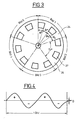
- FIG. 3 shows a top view of an angle encoder disk 24 for equipping the shaft rotation angle by means of a pho toelectronic scanning device, which consists of a light source and a light sensor, which are arranged on both sides of the angle encoder disc 24 in the region of the slots or openings 25 and the webs 26 located therebetween.
- a pho toelectronic scanning device which consists of a light source and a light sensor, which are arranged on both sides of the angle encoder disc 24 in the region of the slots or openings 25 and the webs 26 located therebetween.
- the angle encoder disk 24 shown in FIG. 3 has ten openings 25 and ten webs 26 located between them.
- a rotation angle of 72 ° corresponding to two openings 25 and two webs 26 corresponds to the film transport of a film image, so that five images are positioned with a complete rotation of the angle encoder disc 24.
- the light source and the light sensor of the angle transmitter device By appropriate positioning of the light source and the light sensor of the angle transmitter device, for example, when the center of the light beam rests on an edge of an opening 25, an image is centered on the film relative to the image window 8 according to FIG. 1. In this position, half of the light beam falls through the opening 25, while the other half is covered by a web 26 of the angle encoder disc 24. In this position, the DC power amplifier 29 connected to the light sensor is adjusted to a zero output signal.
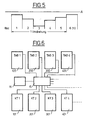
- the DC power amplifier 29 As soon as the electric motor 21 rotates the angle encoder disk 24 according to FIG. 1, the DC power amplifier 29 generates an approximately sinusoidal output signal shown in FIG. 4, which consists of two positive and two negative half-waves.
- fer occurs at the end of an image step technical inaccuracies of the angle encoder disc, the film transport sprocket and due to eccentricities of the motor shaft, a deviation of the film image in the image position from the setpoint position. This error repeats every time the film sprocket is rotated.
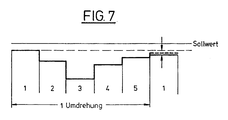
- FIG. 5 shows a schematic representation of the deviations of the individual image stand positions of the film images 1 to 5 during one revolution of the film transport sprocket from a setpoint position A, which corresponds to the correct positioning of a film image in front of the image window.
- the relevant value is then called up for each projection of a film image and specified as a setpoint correction, so that the relevant film image is finally positioned by this correction value.
- the angle encoder disk is offset by a predetermined amount each time a film image is positioned, so that the sensor device detects an exact positioning and stops the film. In this way, device-specific inaccuracies and the resulting device-specific image position errors for each film frame are eliminated and exact picture positioning is ensured.
- the second periodic, operational error which also occurs repeatedly with every fifth film frame, is due to variations in the film channel between the film transport sprocket and the film pressure skid during one revolution caused by non-roundness and eccentricities of the motor shaft and film transport sprocket and is determined by the film type (thin / thick film , stiff / soft film), signs of wear of film transport sprocket, film channel and motor bearings, contamination of the angle encoder disc, etc. affected.
- error tables are stored for the various cases occurring in operation, for example depending on the different types of film.
- an error table is determined that most closely matches the measured values.
- a correction table assigned to this error table is then determined as the optimal correction table and used to correct the image positioning.
- FIG. 6 schematically shows the memory organization in connection with a higher-level control and regulating device, which is preferably designed as a processor.
- the memory assigned to the processor 15 contains a multiplicity of tables 100 to 400 which contain different errors which occur during operation. These errors can depend, for example, on the type of film.
- a measuring device 16 connected to the processor 15 constantly detects the film standstill positions and outputs the detected values to the processor 15. This leads you Comparison of the measured values recorded with the values stored in the various tables 100 to 400 and in this way determines the error table which comes closest to the deviations recorded by the measuring device 16.
- a correction table 101 to 401 belonging to the relevant error table is then selected by the processor 15 as the optimal correction table and used to correct the image positioning by figuratively speaking, the angle encoder disk is correspondingly shifted with each image positioning.
- the standstill positions of the film images are continuously measured by a perforation reading and a stored error table is continuously corrected.
- the measured inaccuracies are summed up over a large number of images and subtracted by the number of measured images, so that an average value is supplied to the position controller for correction.
- FIG. 7 shows a schematic representation of the averaging of the image positioning over a large number of measured images, by averaging a positional deviation of the film image to be positioned during a full revolution of the film transport sprocket in accordance with the dashed representation.
- the embodiment of the invention is not limited to the preferred exemplary embodiment specified above. Rather, a number of variants are conceivable which make use of the solution shown, even in the case of fundamentally different types.
- the implementation is not limited to implementation with discrete logic modules, but can also advantageously be implemented with programmed logic, preferably using a microprocessor.
Landscapes
- Physics & Mathematics (AREA)
- General Physics & Mathematics (AREA)
- Projection-Type Copiers In General (AREA)
- Controlling Rewinding, Feeding, Winding, Or Abnormalities Of Webs (AREA)
Abstract
Description
Die Erfindung betrifft Verfahren zur Korrektur von Höhenbildstandsfehlern bei der Wiedergabe von intermittierend transportierten, perforierten Laufbildfilmen nach dem Oberbegriff des Anspruchs 1 Filmtransportvorrichtungen zur Durchführung der Verfahren.The invention relates to methods for correcting height image error in the playback of intermittently transported, perforated motion picture films according to the preamble of
Aus der DE-PS 27 22 378 ist eine Filmtransportvorrichtung mit einer von einem Elektromotor intermittierend angetriebenen Filmtransportzahnrolle bekannt, deren Zähne in die Perforation des Filmes eingreifen und diesen schrittweise transportieren. Eine Steuervorrichtung steuert den Antriebsmotor der Filmtransportzahnrolle so an, daß dieser den Film um jeweils eine Bildbreite vorschiebt.From DE-PS 27 22 378 a film transport device is known with a film transport sprocket driven intermittently by an electric motor, the teeth of which engage in the perforation of the film and transport it step by step. A control device controls the drive motor of the film transport sprocket so that it advances the film by one frame width.
Der Filmtransport wird durch ein dem Antriebsmotor der Filmtransportzahnrolle zugeführtes Stromprofil bei jedem Bildschritt in eine Beschleunigungsphase, in eine Verzögerungsphase und in eine Positionsregel- bzw. Endpositionierungsphase unterteilt.The film transport is divided into an acceleration phase, a deceleration phase and a position control or end positioning phase by a current profile supplied to the drive motor of the film transport sprocket at each image step.
Zur Endpositionierung ist ein Markierungsdetektor vorgesehen, der in fester räumlicher Beziehung zu den einzelnen Filmbildern stehende Markierungen auf dem Film abtastet und daraus Steuersignale für den Antriebsmotor erzeugt, so daß der Film je nach Lage der Abweichung der filmfesten Markierung von einer vorgegebenen Sollwertposition weiter vorwärts oder rückwärts transportiert wird. Daran anschließend wird die Abweichung von der Sollwertposition erneut detektiert und ggf. das Endpositionieren des Films wiederholt, bis die Sollwertposition erreicht ist. Als filmfeste Markierung dienen die Perforationslöcher des Films oder auf den Film aufbelichtete Markierungen.A mark detector is provided for final positioning, which scans marks on the film which are in a fixed spatial relationship to the individual film images and generates control signals for the drive motor therefrom, so that the film continues to move forwards or backwards depending on the position of the deviation of the film-fixed mark from a predetermined desired value position is transported. The deviation from the setpoint position is then detected again and, if necessary, the end positioning of the film is repeated until the setpoint position is reached. The perforation holes in the film or markings exposed on the film serve as film-proof markings.
Aus der DE-OS 32 17 014 ist eine Filmtransportvorrichtung mit einem von einem Antriebsmotor angetriebenen Greiferschaltwerk bekannt, dessen Transport- und Sperrgreifer mit Spiel in die Perforation des Filmes eingreifen und den Film schrittweise um jeweils eine Bildbreite vorschieben und am Bildfenster endpositionieren. Die Endpositionierung der zu projizierenden Filmbilder erfolgt entweder unter Verwendung des wiederzugebenden Filmbildes selbst oder unter Verwendung einer dem Filmbild zugeordneten Referenzmarkierung.From DE-OS 32 17 014 a film transport device with a gripper switching mechanism driven by a drive motor is known, the transport and locking grippers of which engage with play in the perforation of the film and Advance the film one frame width at a time and position it at the image window. The final positioning of the film images to be projected takes place either using the film image to be reproduced itself or using a reference marking assigned to the film image.
Da jeder Bildschritt bei den bekannten Filmtransportvorrichtungen eine Zeitspanne von nur 10 Millisekunden benötigt, bleibt bei einer Bildfolge von 24 Bildern pro Sekunde, was etwa 41 Millisekunden entspricht, eine Zeit von 31 Millisekunden zur Belichtung bzw. Projektion eines Filmbildes, wodurch eine große Bildhelligkeit und Bildqualität sichergestellt wird.Since each image step in the known film transport devices requires a time span of only 10 milliseconds, with an image sequence of 24 frames per second, which corresponds to approximately 41 milliseconds, there is a time of 31 milliseconds for the exposure or projection of a film image, which results in great image brightness and image quality is ensured.
Bei beiden bekannten Vorrichtungen zur Korrektur von Höhenbildstandsfehlern sind filmfeste Markierungen wie Perforationslöcher des Films oder auf den Film aufbelichtete Markierungen erforderlich, um Bildstandsabweichungen zu korrigieren und Bildsprünge zu vermeiden. Diese zusätzliche Positionierungshilfe in Form von filmfesten Markierungen ist erforderlich, obwohl die elektronische Positionierung einer Filmtransportzahnrolle wie beim Gegenstand der DE-PS 27 22 378 über eine Winkelgeberscheibe, einen Positionsregler und einen Gleichstromleistungsverstärker sehr genau möglich ist.In both known devices for correcting height image error, film-fixed markings such as perforation holes in the film or markings exposed on the film are required in order to correct deviations in the image position and to avoid image jumps. This additional positioning aid in the form of film-fixed markings is necessary, although the electronic positioning of a film transport sprocket as in the subject of DE-PS 27 22 378 is very precisely possible via an angle encoder disk, a position controller and a DC power amplifier.
Trotz dieser elektromechanisch exakten Positionierung der Filmtransportzahnrolle und einer notwendigen kraftschlüssigen Kopplung zwischen den Zähnen der Filmtransportzahnrolle und den Perforationslöchern treten in der Praxis noch merkliche Bildstandsschwankungen auf. Diese sind zum einen auf fertigungstechnische Ungenauigkeiten der mechanischen Filmpositionierungselemente sowie auf betriebsabhängige Einflußgrößen wie Filmart, Abnutzung der Filmtransportzahnrolle, des den Film führenden Filmkanals, des Motorlagers sowie auf Verunreinigungen der Winkelgebereinrichtung zurückzuführen.Despite this electromechanically exact positioning of the film transport sprocket and a necessary non-positive coupling between the teeth of the film transport sprocket and the perforation holes occur in practice still noticeable fluctuations in image position. These are due on the one hand to manufacturing inaccuracies of the mechanical film positioning elements and to operational-dependent influencing variables such as film type, wear of the film transport sprocket, the film channel carrying the film, the motor mount and contamination of the angle encoder device.
Die aus der DE-PS 27 22 378 sowie der DE-PS 32 17 014 bekannte Einzelbildkorrektur weist zudem den Nachteil auf, daß die filmfeste Markierung zur Einzelbildkorrektur sehr exakt erfaßt werden und auch bei häufigem Betrieb eindeutig identifizierbar sein muß. Verschiedene Störeinflüsse beeinträchtigen jedoch die Perforationslöcher des Films oder filmfester, auf den Film aufbelichteter Markierungen, da beispielsweise die Perforationslochkante aufgerauht, deformiert oder verschmutzt sein kann oder ein unterschiedlicher Reflektionsgrad eine aufbelichtete Markierung nur ungenau erkennen läßt.The single image correction known from DE-PS 27 22 378 and DE-PS 32 17 014 also has the disadvantage that the film-proof marking for single image correction must be detected very precisely and must be clearly identifiable even when used frequently. However, various interferences affect the perforation holes of the film or film-fixed markings exposed on the film, since, for example, the perforation hole edge can be roughened, deformed or soiled or a different degree of reflection can only inaccurately identify an exposed marking.
Aufgabe der vorliegenden Erfinung ist es, Verfahren sowie Vorrichtungen zur Korrektur von Höhenbildstandsfehlern bei der Wiedergabe von intermittierend transportierten, perforierten Laufbildfilmen anzugeben, die Höhenbildstandsfehler auf einfache Weise ohne zusätzliche elektromechanische Nachpositionierungen minimieren und bei deren Anwendung die Erfassung filmfester Markierungen und deren durch äußere Störeinflüsse bedingte Meßungenauigkeiten nicht erforderlich ist.The object of the present invention is to provide methods and devices for correcting elevation error in the playback of intermittently transported, perforated motion picture films, which minimize elevation error in a simple manner without additional electromechanical repositioning and, when used, the detection of film-fixed markings and their measurement inaccuracies caused by external interference is not required.
Diese Aufgabe wird erfindungsgemäß dadurch gelöst, daß die Bildstandspositionen mit einem geometrisch exakten Meßfilm über eine Vielzahl Bilder gemessen, die jeweiligen Bildstandspositionene gespeichert und die Stellung der Winkelgebereinrichtung um einen Korrekturwert gegenüber der Filmtransportzahnrolle verändert wird.This object is achieved in that the image positions with a geometrically exact measuring film Measured over a large number of images, the respective image position positions are stored and the position of the angle transmitter device is changed by a correction value relative to the film transport sprocket.
Die erfindungsgemäße Lösung ermöglicht eine hochgenaue Positionierung der Filmbilder unter Ausschluß gerätespezifischer Bildstandsfehler, ohne daß Endpositionierungseinrichtungen und filmfeste Markierungen mit ihren möglichen Störeinflüssen erforderlich sind.The solution according to the invention enables high-precision positioning of the film images to the exclusion of device-specific image position errors, without the need for end positioning devices and film-fixed markings with their possible interference.
Der erfindungsgemäßen Lösung liegt die Überlegung zugrunde, daß die elektronische Positionierung der Filmtransportzahnrolle über eine Winkelgebereinrichtung, einen Positionsregler, einen Gleichstromleistungsverstärker und einen hochdynamischen Gleichstrommotor sehr genau möglich ist, wobei die exakte Übertragung der Endposition jedes Filmbildes durch ein langsames, aperiodisches Einziehen des Films gegen eine Filmreibkraft zu erreichen ist. Damit liegt der Film fest an der Zahnflanke an, was wegen des unvermeidlichen Spiels zwischen Zahn und Perforierung notwendig ist.The solution according to the invention is based on the consideration that the electronic positioning of the film transport sprocket via an angle encoder device, a position controller, a DC power amplifier and a highly dynamic DC motor is possible very precisely, the exact transfer of the end position of each film frame by a slow, aperiodic drawing of the film against one Film friction can be reached. The film is firmly attached to the tooth flank, which is necessary because of the inevitable play between the tooth and the perforation.
Trotz dieser elektromechanischen exakten Positionierung der Filmtransportzahnrolle und der kraftschlüssigen Filmkopplung treten in der Praxis noch merkliche Bildstandsschwankungen auf. Wegen der sehr hohen Drehbeschleunigung der Filmtransportzahnrolle ist es aus physikalischen Gründen erforderlich, eine Filmtransportzahnrolle mit einem solchen Durchmesser zu verwenden, daß bereits ein Bruchteil einer Umdrehung einer Filmvorschubbewegung eines Bildes entspricht.Despite this precise electromechanical positioning of the film transport sprocket and the frictional film coupling, there are still noticeable fluctuations in image position in practice. Because of the very high rotational acceleration of the film transport sprocket, it is necessary for physical reasons to use a film transport sprocket with a diameter such that a fraction of a revolution corresponds to a film feed movement of an image.
Durch fertigungstechnische Ungenauigkeiten der mechanischen Filmpositionierungselemente wie Winkelgebescheibe, Filmtransportzahnrolle und Exzentrizitäten des gemeinsamen Drehmittelpunktes werden die einzelnen Filmbilder innerhalb einer Umdrehung eine Abweichung von der Sollposition aufweisen. Bei jeder Umdrehung wird sich dieser Bildstandsfehler wiederholen.Due to manufacturing inaccuracies of the mechanical film positioning elements such as angular sheave, film transport sprocket and eccentricities of the common center of rotation, the individual film images will deviate from the desired position within one revolution. With every turn this image error will repeat itself.
Ist eine Umdrehung der Filmtransportzahnrolle mit der Projektion von n Bildern gleichzusetzen, so steht jedes n-te Bild wieder an derselben Position. Dieser periodischsystematische Fehler ist eine konstante, gerätespezifische Größe, die nachfolgend als gerätespezifischer Bildstandsfehler bezeichnet wird.If one revolution of the film transport sprocket equates to the projection of n images, then every nth image is again in the same position. This periodic systematic error is a constant, device-specific variable, which is referred to below as a device-specific image position error.
Da es sich um eine reproduzierbare Größe handelt, kann erfindungsgemäß durch einmalige Messung der Bildstandspositionen über eine größere Anzahl von Bildern beispielsweise durch einfache Perforationslesung mittels eines geometrisch exakten Meßfilmes, eine feste Speicherung z.B. in einem EPROM und eine Korrektur der Sollage um den entsprechenden Betrag der gerätespezifische Bildstandsfehler eliminiert werden.Since it is a reproducible size, according to the invention, one-time measurement of the image position over a larger number of images, for example by simple perforation reading using a geometrically exact measuring film, a fixed storage e.g. in an EPROM and a correction of the target position by the corresponding amount of the device-specific image error are eliminated.
Ein weiterer periodischer Fehler, der sich ebenfalls mit jedem n-ten Filmbild wiederholt, wobei n Filmbilder einer Umdrehung der Filmtransportzahnrolle entsprechen, besteht darin, daß aufgrund der Variation des Filmkanals zwischen der Filmtransportzahnrolle und einer Filmandruckkufe während einer Umdrehung, verursacht durch Unrundheiten und Exzentrizitäten von Motorwelle und Zahntrommel, der Film bei einer Umdrehung mehr oder weniger auf der Filmtransportzahnrolle aufliegt und somit auch auf einer unterschiedliche Höhe auf einer Zahnflanke der Filmtransportzahnrolle aufliegen kann.Another periodic error that also repeats with every nth film frame, where n film frames correspond to one revolution of the film transport sprocket, is that due to the variation of the film channel between the film transport sprocket and a film pressure skid during one rotation, caused by out-of-roundness and eccentricities of Motor shaft and toothed drum, the film rests more or less on the film transport sprocket during one revolution and can therefore also rest on a tooth flank of the film transport sprocket at a different height.
Bei diesem nachstehend als zweiten periodischen Fehler bezeichneten weiteren Fehler handelt es sich jedoch nicht um eine konstante, gerätespezifische sondern um eine betriebsabhängige Größe.However, this further error, referred to below as the second periodic error, is not a constant, device-specific, but an operation-dependent variable.
Einflußgrößen auf diesen zweiten periodischen Fehler sind die Filmart, da sich beispielsweise ein dünner Film im Filmkanal mit mehr Spielraum bewegt als ein dicker Film, ein steiferer Film sich im variablen Filmkanal anders verhält als ein weicher Film, Abnutzungen an der Filmtransportzahnrolle, am Filmkanal und am Motorlager, Verschmutzungen der Winkelgebereinrichtung usw.Influencing factors on this second periodic error are the type of film, since, for example, a thin film moves in the film channel with more latitude than a thick film, a stiffer film behaves differently in the variable film channel than a soft film, wear on the film transport sprocket, on the film channel and on Motor bearings, contamination of the angle encoder device, etc.
Ein Verfahren zur Korrektur des zweiten, möglichen periodischen Bildstandsfehlers besteht erfindungsgemäß darin, daß Fehlertabellen für im Projektionsbetrieb vorkommende Bildstandsfehler gespeichert werden, die Bildstandspositionen kontinuierlich oder zu frei wählbaren Zeitpunkten gemessen und die erfaßten Meßwerte mit den in den Fehlertabellen gespeicherten Werten verglichen und eine die Meßwerte optimal repräsentierende Fehlertabelle ermittelt und eine zu dieser Fehlertabelle gehörige Korrekturtabelle ausgewählt wird, deren Korrekturwerte an die Regeleinrichtung abgegeben werden.According to the invention, a method for correcting the second, possible periodic image position error consists in storing error tables for image position errors occurring in the projection mode, measuring the image position positions continuously or at freely selectable points in time and comparing the measured values recorded with the values stored in the error tables and optimally measuring the values representative error table is determined and a correction table belonging to this error table is selected, the correction values of which are output to the control device.
Ein alternatives Verfahren zur Reduzierung des zweiten periodischen Fehlers besteht darin, daß die Bildstandsposi tionen kontinuierlich durch Erfassen einer filmfesten Markierung gemessen werden, mit den fortlaufenden Meßwerten eine gespeicherte Fehlertabelle fortlaufend korrigiert wird und die Abweichungen der Istwertpositionen des Bildstandes von einer die korrekte Bildstillstandsposition wiedergenden Sollwertvorgabe über eine Vielzahl Bilder summiert und die summierten Differenzwerte dividiert durch die Anzahl gemessener Werte als Mittelwert zur Korrektur der Regeleinrichtung zugeführt wird.An alternative method for reducing the second periodic error is that the image stand positions tion can be measured continuously by capturing a film-proof mark, a stored error table is continuously corrected with the continuous measurement values, and the deviations of the actual position of the image position from a setpoint value representing the correct image stop position are summed up over a large number of images and the summed difference values divided by the number of measured values as Average value for correction of the control device is supplied.
Mit beiden Verfahren können Höhenbildstandfehler auf sehr einfache Weise ausreichend minimiert werden, ohne daß zusätzliche elektromechanische Nachpositionierungseinrichtungen erforderlich sind, die zusätzlichen Störeinflüssen unterliegen.With both methods, height image standing errors can be minimized in a very simple manner without additional electromechanical repositioning devices being required, which are subject to additional interference.
Die ständige Messung der Bildpositionskorrektur erst nach Mittelung über mehrere Bilder oder ein Vergleich mit einer festen Fehlertabelle weist gegenüber einer Einzelbildkorrektur den wesentlichen Vorteil auf, daß die mit den verschiedenen Störeinflüssen behafteten Perforierungsmessungen oder Erfassungen filmfester Markierungen nicht direkt beim einzelnen Bild zur Endpositionierung herangezogen werden und somit praktisch durch die Ausmittelung der Fehler eine genauere Bildpositionierung möglich ist.The constant measurement of the image position correction only after averaging over several images or a comparison with a fixed error table has the essential advantage over a single image correction that the perforation measurements or recordings of film-fixed markings, which are affected by the various interfering influences, are not directly used for the final positioning of the individual image and thus a more precise image positioning is practically possible by averaging the errors.
Schließlich kann das Verfahren zur Reduzierung des gerätespezifischen Bildstandsfehlers mit den beiden Verfahren zur Reduzierung des zweiten periodischen Fehlers kombiniert werden, so daß sowohl fertigungstechnische Ungenauigkeiten der mechanischen Filmpositionierungselemente als auch betriebsabhängige Größen bei der Endpositionierung der einzelnen Filmbilder berücksichtigt werden, so daß die auf diese Einflußgrößen zurückzuführenden Höhenbildstandsfehler ausreichend minimiert werden, ohne daß eine zusätzliche elektromechanische Nachpositionierungseinrichtung erforderlich ist, deren Genauigkeit von der Größe der Störeinflüsse bei der Perforierungsmessung oder Erfassung filmfester Markierungen abhängig ist.Finally, the method for reducing the device-specific image position error can be combined with the two methods for reducing the second periodic error, so that both technical manufacturing inaccuracies of the mechanical film positioning elements and Operation-dependent variables are also taken into account in the final positioning of the individual film images, so that the height image errors due to these influencing variables are sufficiently minimized without the need for an additional electromechanical repositioning device, the accuracy of which depends on the size of the disturbing influences during perforation measurement or recording of film-fixed markings.
Anhand eines in der Zeichnung dargestellten Ausführungsbeispieles soll der der Erfindung zugrundeliegenden Gedanke näher erläutert werden. Es zeigen:
Figur 1 eine schematische Darstellung der einzelnen Antriebsteile eines Filmprojektors;Figur 2 einen Querschnitt durch eine Filmtransporteinrichtung mit einer Filmtransportzahnrolle;Figur 3 eine Draufsicht auf eine Winkelgeberscheibe einer Winkelgebereinrichtung;Figur 4 eine zeitliche Darstellung des von der Winkelgebereinrichtung erfaßten Meßsignals;Figur 5 eine schematische Darstellung der Abweichung der einzelnen Filmbilder von einer exakten Sollwertlage bei einer Umdrehung der Filmtransportzahnrolle;Figur 6 ein Blockschaltbild der Speicherorganisation der Regeleinrichtung zur Positionierung der Filmtransportzahnrolle und- Figur 7 eine schematische Darstellung der Methode zur Korrektur eines zweiten periodischen Fehlers.
- Figure 1 is a schematic representation of the individual drive parts of a film projector;
- FIG. 2 shows a cross section through a film transport device with a film transport sprocket;
- FIG. 3 shows a plan view of an angle encoder disk of an angle encoder device;
- FIG. 4 shows a time representation of the measurement signal detected by the angle encoder device;
- FIG. 5 shows a schematic illustration of the deviation of the individual film images from an exact desired value position during one revolution of the film transport sprocket;
- Figure 6 is a block diagram of the memory organization of the control device for positioning the film transport sprocket and
- Figure 7 is a schematic representation of the method for correcting a second periodic error.
Die in Figur 1 dargestellte schematische perspektivische Ansicht der wesentlichen Antriebsteile des erfindungsgemäßen Filmprojektors zeigt die Filmtransporteinrichtung 2, die Vor- und Nachwickeleinrichtungen 3, 4, die von einer gemeinsamen Antriebseinrichtung 5 angetrieben werden, die die Filmspulen tragenden Wickeleinrichtungen 6, 7 sowie in vereinfachter schematischer perspektivischer Darstellung die zur Aufnahme der Filmschleifen zu beiden Seiten des Bildfensters 8 dienenden Filmschleifenkanäle 9, 10.The schematic perspective view of the essential drive parts of the film projector according to the invention shown in FIG. 1 shows the
Die Filmtransporteinrichtung 2 enhält einen Hauptmotor 21, der aus einem hochdynamischen Gleichstromservomotor besteht, der seine Drehbewegung über eine direkt angetriebene Filmzahnrolle 22 auf den Film 1 überträgt. Über eine Welle 23 ist der Hauptmotor 21 fest mit einer Winkelgeberscheibe 24 eines Sensors 26 verbunden, der mittels einer opto-elektronischen Positions-Abtasteinrichtung 25 die exakte Stellung des Hauptmotors 21 erfaßt und weiterleitet.The
Die Vor- und Nachwickeleinrichtungen 3, 4 enthalten eine Antriebswelle 31, 41, die fest mit je einer Zahntrommel 32, 42 verbunden sind und den eingelegten Film kontinuierlich transportieren. Die Antriebswellen 31, 41 sind über Riemen 56, 57 mit Antriebsrollen 52 der Antriebseinrichtung 5 verbunden, die über eine Welle starr mit einem Antriebsmotor 51 gekoppelt ist, der aus einem geregelten Gleichstrommotor besteht, dessen Drehzahl proportional zur eingestellten Bildfrequenz geregelt wird. Zur Drehzahlund Positionserfassung des Antriebsmotors 51 dient eine fest mit der Motorwelle verbundene Winkelgeberscheibe 53, die zusammen mit einer optoelektronischen Abtasteinrichtung 54 einen Sensor 55 bildet.The pre-winding and
Die Wickeleinrichtungen 6, 7 zur Aufnahme der Filmspulen enthalten einen Wickelteller 62, 72, die über eine Welle mit je einem Wickelmotor 61, 71 verbunden sind, der als Gleichstrommotor ausgebildet ist. Zur Drehzahl- und Drehrichtungserfassung der Wickelmotoren 61, 71 dient eine fest mit der Welle des jeweiligen Wickelmotors 61, 71 verbundene Winkelgeberscheibe 63, 73, die zusammen mit einer optoelektronischen Abtasteinrichtung 64, 74 eine Sensoreinrichtung 65, 75 bildet.The
Die Filmschleifenkanäle 9, 10 dienen zur Aufnahme der zu beiden Seiten des Bildfensters 8 gebildeten Filmschleifen, wobei im vorliegenden Fall aufgrund der speziellen Ausgestaltung der Steuer- und Regeleinrichtung nur eine Schleifenmeßeinrichtung 11 in dem links vom Bildfenster 8 angeordneten Filmschleifenkanal 9 vorgesehen ist. Die Schleifenmeßeinrichtung 11 kann aus einer Reflexionslichtschranke oder einer Leuchtdiode in Verbindung mit einem gegenüberliegenden Fototransistor bestehen.The film loop channels 9, 10 serve to receive the film loops formed on both sides of the image window 8, in the present case only one
Die Wickelteller 62, 72 dienen zur Aufnahme der Filmspulen, wobei der Film wahlweise vom linken Wickelteller 62 abgewickelt und durch den nachstehend beschriebenen Filmkanal zum rechten Wickelteller 72 oder umgekehrt bewegt werden kann. Nach Wahl des Benutzers kann der Film 1 auch in beliebiger Weise auf die Wickelteller 62, 72 aufgelegt werden.The
Zwischen den Vor- und Nachwickeleinrichtungen 3, 4 ist das Bildfenster 8 und die Filmtransporteinrichtung 2 mit der Filmzahnrolle 22 angeordnet. Das Bildfenster 8 ist Teil einer Filmanlegeschiene, die im Bereich der Filmzahnrolle 22 eine gebogene Filmkufe aufweist, deren Krümmung dem Durchmesser der Filmzahnrolle 22 angepaßt ist.The image window 8 and the
Ein übergeordnetes Steuer-, Regel- und Überwachungssystem 15 ist mit einer Eingabetastatur 16 zur Eingabe gewünschter Filmprojektorfunktionen wie Bildtransport vorwärts und rückwärts mit variabler Transportgeschwindigkeit, Suchlauf, schneller Vor- und Rücklauf oder dergleichen verbunden. Sie weist vorzugsweise einen Mikroprozessor auf, der mit einem Speicher zur Speicherung beliebiger Funktionen des Filmprojektors verbunden ist.A higher-level control, regulation and
Das übergeordnete Steuer-, Regel- und Überwachungssystem 15 ist ausgangsseitig mit den elektronischen Steuer- und Regelteilen 20, 50, 60, 70 für die einzelnen Antriebsteile des Filmprojektors verbunden. Die Ausgänge der elektronischen Steuer- und Regelteile 20, 50, 60, 70 sind über nachgeschaltete Gleichstrom-Leistungsverstärker 29, 59, 69, 79 mit dem Hauptmotor 21 der Filmtransporteinrichtung 2, dem Antriebsmotor 51 der Antriebseinrichtung 5 sowie dem linken Wickelmotor 61 und rechten Wickelmotor 71 der beiden Wickeleinrichtungen 6, 7 verbunden.The higher-level control, regulating and
Die mit den Motorwellen gekoppelten Sensoren 25 und 55 des Hauptmotors 21 und des Antriebsmotors 51 geben entspre chende Positions-, Drehzahl- und/oder Drehrichtungssignale an die Eingänge der zugeordneten Steuer- und Regelteile 20, 50 sowie an das übergeordnete Steuer-, Regel- und Überwachungssystem ab. Die mit den Motorwellen der Wickelmotoren 61, 71 gekoppelten Sensoren 65, 75 geben Ausgangssignale ausschließlich an jeweils einen Eingang des übergeordneten Steuer-, Regel- und Überwachungssystems 15 ab.The coupled to the
Das von der Schleifenmeßeinrichtung abgegebene Signal wird ebenfalls an einen Eingang des Steuer-, Regel- und Überwachungssystems 15 gelegt.The signal emitted by the loop measuring device is also applied to an input of the control, regulating and
Der in Figur 2 dargestellte Querschnitt durch eine Filmtransporteinrichtung zeigt eine mit 2 Zahnkränze 4, 5 versehene Filmtransportzahnrolle, die fest mit der Welle eines Antriebsmotors 2 gekoppelt ist, auf dessen Welle auch eine Winkelgeberscheibe 3 zur exakten Positionierung des Antriebsmotors 2 angeordnet ist. Der obere und untere Zahnkranz 4, 5 der Filmtransportzahnrolle 1 greift in entsprechende Perforationsreihen 61, 62 eines Films 6 ein, wobei der Eingriff durch eine nicht näher dargestellte Führung in Form einer Filmkufe oder dergleichen herbeigeführt wird.The cross section shown in FIG. 2 through a film transport device shows a film transport sprocket provided with 2 ring gears 4, 5, which is firmly coupled to the shaft of a
Dabei erfolgt der Eingriff der Zähne der Filmtransportzahnrolle in die Filmperforation über einen von der Filmbahn abhängigen Umfangsbereich der Filmtranportzahnrolle, so daß mehrere Zähne jedes Zahnkranzes 4, 5 der Filmtransportzahnrolle 1 gleichzeitig in entsprechende Perforationslöcher der Filmperforation eingreifen. Üblicherweise greifen gleichzeitig 4 bis 6 Zähne der Filmtransportzahnrolle 1 in die Filmperforation ein.The teeth of the film transport sprocket engage in the film perforation over a circumferential region of the film transport sprocket that is dependent on the film path, so that several teeth of each
Der Eingriff der Zähne der Filmtransportzahnrolle 1 in die Filmperforation erfolgt dabei unter Einhaltung eines bestimmten Spiels, d.h., die Zahndicke der Zähne der Filmtransportzahnrolle 1 ist geringer als die Perforationsweite. Auf diese Weise wird vermieden, daß die Zähne der Filmtransportzahnrolle 1 an den Perforationsflanken beidseitig anliegen, was wegen der Filmspannung zu einer Beschädigung der Filmperforation und zu einem erhöhten Geräuschpegel führen würde.The teeth of the
Dieses Spiel zwischen den Zähnen der Filmtransportzahnrolle 1 und der Filmperforation führt aber auch bei Einhaltung einer vorbestimmten Filmspannung zu ungenauer Positionierung der einzelnen Filmbilder vor dem Bildfenster 8, so daß der Vorteil einer exakten Positionierung mit Hilfe eines Winkelgebersystems für den Antriebsmotor 2 durch diese ungenaue Führung des Films 6 beseitigt wird.This play between the teeth of the
Um die genaue Positionierung des Films, die durch die Verwendung eines Antriebsmotors für die Filmtransportzahnrolle mit einem Winkelgebersystem geschaffen wird, auf die Positionierung des Films vor dem Bildfenster zu übertragen, wird die Bewegung des Films 6 vor der Projektion eines Filmbildes so eingestellt, daß die in Drehrichtung der Filmtransportzahnrolle 1 vordere Flanke eines Zahns 10 bis 14 der Filmtransportzahnrolle 1 an der Vorderkante mindestens eines Perforationslochs der Filmperforation im Augenblick der Projektion eines Filmbildes anliegt.In order to transfer the exact positioning of the film created by the use of a drive motor for the film transport sprocket with an angle encoder system to the positioning of the film in front of the image window, the movement of the
Figur 3 zeigt eine Draufsicht auf eine Winkelgeberscheibe 24 zur Bestückung des Wellendrehwinkels mittels einer pho toelektronischen Abtasteinrichtung, die aus einer Lichtquelle und einem Lichtsensor besteht, die auf beiden Seiten der Winkelgeberscheibe 24 im Bereich der Schlitze bzw. Öffnungen 25 und der dazwischen befindlichen Stege 26 angeordnet sind.FIG. 3 shows a top view of an
Die in Figur 3 dargestellte Winkelgeberscheibe 24 weist zehn Öffnungen 25 sowie zehn dazwischen befindliche Stege 26 auf. Ein Drehwinkel von 72° entsprechend zwei Öffnungen 25 und zwei Stegen 26 entspricht dem Filmtransport eines Filmbildes, so daß bei einer vollständigen Umdrehung der Winkelgeberscheibe 24 fünf Bilder positioniert werden.The
Durch entsprechende Positionierung der Lichtquelle und des Lichtsensors der Winkelgebereinrichtung wird beispielsweise dann, wenn die Lichtstrahlmitte an einer Kante einer Öffnung 25 anliegt, ein Bild auf dem Film gegenüber dem Bildfenster 8 gemäß Figur 1 zentriert ist. In dieser Stellung fällt die Hälfte des Lichtstrahles durch die Öffnung 25, während die andere Hälfte durch einen Steg 26 der Winkelgeberscheibe 24 abgedeckt ist. In dieser Position ist der an den Lichtsensor angeschlossene Gleichstromleistungsverstärker 29 auf ein Null-Ausgangssignal justiert.By appropriate positioning of the light source and the light sensor of the angle transmitter device, for example, when the center of the light beam rests on an edge of an
Sobald der Elektromotor 21 gemäß Figur 1 die Winkelgeberscheibe 24 dreht, erzeugt der Gleichstromleistungsverstärker 29 ein in Figur 4 dargestelltes annähernd sinusförmiges Ausgangssignal, das aus jeweils zwei positiven und zwei negativen Halbwellen besteht.As soon as the
Wie der zeitlichen Darstellung gemäß der Figur 4 zu entnehmen ist, tritt am Ende eines Bildschrittes infolge fer tigungstechnischer Ungenauigkeiten der Winkelgeberscheibe, der Filmtransportzahnrolle sowie aufgrund von Exzentrizitäten der Motorwelle eine Abweichung des Filmbildes beim Bildstand von der Sollwertposition auf. Dieser Fehler wiederholt sich bei jeder Umdrehung der Filmtransportzahnrolle.As can be seen from the time representation according to FIG. 4, fer occurs at the end of an image step technical inaccuracies of the angle encoder disc, the film transport sprocket and due to eccentricities of the motor shaft, a deviation of the film image in the image position from the setpoint position. This error repeats every time the film sprocket is rotated.
Bei Verwendung einer Winkelgeberscheibe gemäß Figur 3, der fünf Filmbilder bei einer Umdrehung der Winkelgeberscheibe positioniert werden, steht somit jedes fünfte Bild wieder an derselben Position. Diese Abweichung der Istposition jedes Filmbildes von der korrekten Sollposition ist darauf zurückzuführen, daß mit der Positionierungseinrichtung letztendlich nicht korrekt das Bild vor dem Bildfenster sondern die Winkelgeberscheibe positioniert wird, so daß mechanische Abweichungen zwischen der Winkelgeberscheibe und der Filmtransportzahnrolle bei definierter Anlage des Film an den Zähnen der Filmtransportzahnrolle zu Höhenbildstandsfehlern führen müssen.When using an angle encoder disc according to FIG. 3, which five film images are positioned with one revolution of the angle encoder disc, every fifth image is again at the same position. This deviation of the actual position of each film image from the correct target position is due to the fact that the positioning device ultimately does not correctly position the image in front of the image window, but rather the angle encoder disk, so that mechanical deviations between the angle encoder disk and the film transport sprocket when the film is applied to the teeth in a defined manner the film feed sprocket must lead to height error.
Figur 5 zeigt in schematischer Darstellung die Abweichungen der einzelnen Bildstandspositionen der Filmbilder 1 bis 5 bei einer Umdrehung der Filmtransportzahnrolle von einer Sollwertposition A, die der korrekten Positionierung eines Filmbildes vor dem Bildfenster entspricht.FIG. 5 shows a schematic representation of the deviations of the individual image stand positions of the
Diese in Figur 5 völlig unterschiedlichen Abweichungen, die jedoch teilweise auch miteinander übereinstimmen können, werden erfindungsgemäß mit einem äußerst exakten Meßfilm, der geometrische Filmfehler ausschließt, über eine Vielzahl von Bildern beispielsweise durch eine Perfora tionslesung einmalig gemessen und in einem projektoreigenen Speicher, beispielsweise einem EPROM, abgespeichert. Die Messung erfolgt dabei in beiden Drehrichtungen der Filmtransportvorrichtung, so daß beispielsweise bei einer Filmtransportzahnrolle mit am Umfang gleichmäßig verteilten zwanzig Zähnen vierzig Korrekturwerte gespeichert werden.These deviations, which are completely different in FIG. 5, but which in some cases can also coincide with one another, are achieved according to the invention with an extremely precise measuring film, which excludes geometric film errors, over a large number of images, for example through a perforation tion reading measured once and stored in a projector-specific memory, for example an EPROM. The measurement is carried out in both directions of rotation of the film transport device, so that for example in a film transport sprocket with twenty teeth evenly distributed around the circumference, forty correction values are stored.
Bei der Projektion eines beliebigen Filmes wird dann bei jeder Projektion eines Filmbildes der betreffende Wert abgerufen und als Sollwertkorrektur vorgegeben, so daß eine Endpositionierung des betreffenden Filmbildes um diesen Korrekturwert erfolgt.When projecting any film, the relevant value is then called up for each projection of a film image and specified as a setpoint correction, so that the relevant film image is finally positioned by this correction value.
Bildlich ausgedrückt wird die Winkelgeberscheibe bei jeder Positionierung eines Filmbildes um einen vorgegebenen Betrag versetzt, so daß die Sensoreinrichtung eine exakte Positionierung erfaßt und den Film stillsetzt. Auf diese Weise werden gerätespezifische Ungenauigkeiten und daraus resultierende gerätespezifische Bildstandsfehler für jedes Filmbild eliminiert und eine exakte Bildpositionierung sichergestellt.Expressed figuratively, the angle encoder disk is offset by a predetermined amount each time a film image is positioned, so that the sensor device detects an exact positioning and stops the film. In this way, device-specific inaccuracies and the resulting device-specific image position errors for each film frame are eliminated and exact picture positioning is ensured.
Der zweite periodische, betriebsabhängige Fehler, der ebenfalls wiederholend mit jedem fünften Filmbild auftritt, ist auf Variationen des Filmkanals zwischen der Filmtransportzahnrolle und der Filmandruckkufe während einer Umdrehung verursacht durch Unrundheiten und Exzentrizitäten von Motorwelle und Filmtransportzahnrolle zurückzuführen und wird von der Filmart (dünner/dicker Film, steifer/weicher Film), Abnutzungserscheinungen von Film transportzahnrolle, Filmkanal und Motorlager, Verschmut zung der Winkelgeberscheibe usw. beeinflußt.The second periodic, operational error, which also occurs repeatedly with every fifth film frame, is due to variations in the film channel between the film transport sprocket and the film pressure skid during one revolution caused by non-roundness and eccentricities of the motor shaft and film transport sprocket and is determined by the film type (thin / thick film , stiff / soft film), signs of wear of film transport sprocket, film channel and motor bearings, contamination of the angle encoder disc, etc. affected.
Zur Verringerung dieses Höhenbildstandsfehlers wird eine zusätzliche Bildstandskorrektur durchgeführt, die auf zwei Arten erfolgen kann.To reduce this height image error, an additional image correction is carried out, which can be done in two ways.
In einem ersten Verfahren zur Minimierung des betriebsabhängigen Höhenbildstandsfehlers werden für die verschiedenen im Betrieb vorkommenden Fälle, beispielsweise abhängig von den verschiedenen Filmarten, Fehlertabellen gespeichert. Durch ständiges Messen der Filmstillstandspositionen und Vergleichen der ermittelten Abweichungen von einer gewünschten Sollwertposition mit den gespeicherten Fehlertabellen wird eine Fehlertabelle ermittelt, die mit den gemessenen Werten am meisten übereinstimmt. Eine dieser Fehlertabelle zugeordnete Korrekturtabelle wird dann als optimale Korrekturtabelle ermittelt und zur Korrektur der Bildpositionierung herangezogen.In a first method for minimizing the operation-dependent height image error, error tables are stored for the various cases occurring in operation, for example depending on the different types of film. By continuously measuring the film standstill positions and comparing the determined deviations from a desired setpoint position with the stored error tables, an error table is determined that most closely matches the measured values. A correction table assigned to this error table is then determined as the optimal correction table and used to correct the image positioning.
Figur 6 zeigt schematisch die Speicherorganisation in Verbindung mit einer übergeordneten Steuer- und Regeleinrichtung, die vorzugsweise als Prozessor ausgebildet ist. Der dem Prozessor 15 zugeordnete Speicher enthält eine Vielzahl von Tabellen 100 bis 400, die unterschiedliche, im Betrieb vorkommende Fehler enthalten. Diese Fehler können beispielsweise vom Filmtyp abhängen.FIG. 6 schematically shows the memory organization in connection with a higher-level control and regulating device, which is preferably designed as a processor. The memory assigned to the
Eine mit dem Prozessor 15 verbundene Meßeinrichtung 16 erfaßt ständig die Filmstillstandspositionen und gibt die erfaßten Werte an den Prozessor 15 ab. Dieser führt einen Vergleich der erfaßten Meßwerte mit den in den verschiedenen Tabellen 100 bis 400 gespeicherten Werten durch und ermittelt auf diese Weise diejenige Fehlertabelle, die den durch die Meßeinrichtung 16 erfaßten Abweichungen am nächsten kommt.A measuring
Eine zu der betreffenden Fehlertabelle gehörende Korrekturtabelle 101 bis 401 wird anschließend vom Prozessor 15 als optimale Korrekturtabelle ausgewählt und zur Korrektur der Bildpositionierung herangezogen, indem bildlich gesprochen die Winkelgeberscheibe bei jeder Bildpositionierung entsprechend verschoben wird.A correction table 101 to 401 belonging to the relevant error table is then selected by the
In einem alternativen Verfahren zur Korrektur betriebsabhängiger Höhenbildstandsfehler werden die Stillstandspositionen der Filmbilder durch eine Perforierungslesung ständig gemessen und eine eingespeicherte Fehlertabelle fortlaufend korrigiert. Die gemessenen Ungenauigkeiten werden über eine Vielzahl von Bildern summiert und durch die Anzahl der gemessenen Bilder subtrahiert, so daß ein Mittelwert zur Korrektur dem Positionsregler zugeführt wird.In an alternative method for correcting operational image height errors, the standstill positions of the film images are continuously measured by a perforation reading and a stored error table is continuously corrected. The measured inaccuracies are summed up over a large number of images and subtracted by the number of measured images, so that an average value is supplied to the position controller for correction.
Figur 7 zeigt in schematischer Darstellung die Mittelung der Bildpositionierung über eine Vielzahl gemessener Bilder, indem eine Lageabweichung des zu positionierenden Filmbildes bei einer vollen Umdrehung der Filmtransportzahnrolle entsprechend der gestrichelten Darstellung gemittelt wird.FIG. 7 shows a schematic representation of the averaging of the image positioning over a large number of measured images, by averaging a positional deviation of the film image to be positioned during a full revolution of the film transport sprocket in accordance with the dashed representation.
Mit einer Kombination der Bildstandskorrektur gemäß Figur mit der Bildstandskorrektur gemäß den Figuren 6 oder 7 können somit Höhenbildstandsfehler optimal korrigiert werden ohne daß zusätzliche, mit zusätzlichen Fehlern behaftete elektromechanische Nachpositionierungseinrichtungen erforderlich sind. Insbesondere wird eine ungenaue Perforantionslesung vermieden, so daß bei der Projektion eines Films mit stark schwankenden Perforationslochabständen nicht zusätzliche Fehler bei der Höhenbildstandspositionierung infolge einer ungenauen Perforationsmessung hinzugefügt werden.With a combination of the image position correction according to FIG. With the image position correction according to FIGS. 6 or 7 can thus be optimally corrected for image height errors without the need for additional electromechanical repositioning devices with additional errors. In particular, an inaccurate perforation reading is avoided, so that when projecting a film with widely fluctuating perforation hole spacings, additional errors in the height image position positioning due to an inaccurate perforation measurement are not added.
Die Erfindung beschränkt sich in ihrer Ausführung nicht auf das vorstehend angegebene bevorzugte Ausführungsbeispiel. Vielmehr ist eine Anzahl von Varianten denkbar, welche von der dargestellten Lösung auch bei grundsätzlich anders gearteten Ausführungen Gebrauch machen. Insbesondere beschränkt sich die Ausführung nicht auf die Realisierung mit diskreten logischen Baugruppen, sondern läßt sich vorteilhaft auch mit programmierter Logik - vorzugsweise unter Verwendung eines Mikroprozessors - realisieren.The embodiment of the invention is not limited to the preferred exemplary embodiment specified above. Rather, a number of variants are conceivable which make use of the solution shown, even in the case of fundamentally different types. In particular, the implementation is not limited to implementation with discrete logic modules, but can also advantageously be implemented with programmed logic, preferably using a microprocessor.
Claims (8)
dadurch gekennzeichnet,
daß die Bildstandspositionen mit einem geometrisch exakten Meßfilm über eine Vielzahl Bilder gemessen, die jeweiligen Bildstandspositionen gespeichert und die Stellung der Winkelgeberscheibe (24) um einen Korrekturwert gegenüber der Filmtransportzahnrolle (22) verändert werden.1. A method for correcting elevation error in the reproduction of an intermittently transported, perforated motion picture film by means of a film transport sprocket which engages in the film perforation and which is driven by an electric motor, the rotor of which is connected to an angle encoder device which sends position signals corresponding to the angular position of the rotor to the electric motor delivers controlling control device,
characterized,
that the image position is measured with a geometrically exact measuring film over a large number of images, the respective image position is stored and the position of the angle encoder disc (24) is changed by a correction value in relation to the film transport sprocket (22).
dadurch gekennzeichnet,
daß Fehlertabellen (100 bis 400) für im Projektionsbetrieb vorkommende Bildstandsfehler gespeichert werden,
daß die Bildstandspositionen gemessen und die erfaßten Meßwerte mit den in den Fehlertabellen (100 bis 400) gespeicherten Werten verglichen werden,
und daß eine die Meßwerte optimal repräsentierende Fehlertabelle (100 bzw. 200 bzw. 300 bzw. 400) ermittelt und eine zu dieser Fehlertabelle gehörige Korrekturtabelle (101 bis 401) ausgewählt wird, deren Korrekturwerte an die Regeleinrichtung (15) abgegeben werden.4. A method for correcting height image error in the reproduction of an intermittently transported, perforated motion picture film by means of a film transport sprocket which engages in the film perforation and which is driven by an electric motor, the rotor of which is connected to an angle transmitter device which sends position signals corresponding to the angular position of the rotor to the electric motor delivers controlling control device,
characterized,
that error tables (100 to 400) are stored for image status errors occurring in projection operation,
that the image stand positions are measured and the recorded measured values are compared with the values stored in the error tables (100 to 400),
and that an error table (100 or 200 or 300 or 400) optimally representing the measured values is determined and a correction table (101 to 401) belonging to this error table is selected, the correction values of which are output to the control device (15).
dadurch gekennzeichnet,
daß die Bildstandspositionen kontinuierlich durch Erfassen einer filmfesten Markierung gemessen werden,
daß mit den fortlaufenden Meßwerten eine gespeicherte Fehlertabelle fortlaufend korrigiert wird und daß die Abweichungen der Istwertpositionen des Bildstandes von einer die korrekte Bildstillstandsposition wiedergenden Sollwertvorgabe über eine Vielzahl Bilder summiert und die summierten Differenzwerte dividiert durch die Anzahl gemessener Werte als Mittelwert zur Korrektur der Regeleinrichtung (15) zugeführt wird.6. A method for correcting elevation error in the reproduction of an intermittently transported, perforated motion picture film by means of a film transport sprocket which engages in the film perforation and which is driven by an electric motor, the rotor of which is connected to an angle encoder device which transmits position signals corresponding to the angular position of the rotor to an electric motor delivers controlling control device,
characterized,
that the image position is continuously measured by capturing a film-proof mark,
that a stored error table is continuously corrected with the continuous measured values and that the deviations of the actual value positions of the image position from a setpoint value representation representing the correct image standstill position are summed up over a plurality of images and the summed difference values divided by the number of measured values are supplied as a mean value for the correction of the control device (15).
dadurch gekennzeichnet,
daß die Bildstandspositionen mit einem Meßfilm über eine Vielzahl Bilder gemessen, die jeweiligen Bildstandspositionen gespeichert und die Stellung der Winkelgebereinrichtung um einen Korrekturwert gegenüber der Filmtransportzahnrolle verändert wird,
daß Fehlertabellen für im Projektionsbetrieb vorkommende Bildstandsfehler gespeichert werden,
daß die Bildstandspositionen kontinuierlich gemessen und die erfaßten Meßwerte mit den in den Fehlertabellen gespeicherten Werten verglichen werden,
und daß eine die Meßwerte optimal repräsentierende Fehlertabelle ermittelt und eine zu dieser Fehlertabelle gehörige Korrekturtabelle ausgewählt wird, deren Korrekturwerte an die Regeleinrichtung abgegeben werden.7. A method for correcting elevation error in the reproduction of an intermittently transported, perforated motion picture film by means of a film transport sprocket which engages in the film perforation and which is driven by an electric motor, the rotor of which is connected to an angle encoder device which sends position signals corresponding to the angular position of the rotor to the electric motor delivers controlling control device,
characterized,
that the image stand positions are measured with a measuring film over a large number of images, the respective image stand positions are stored and the position of the angle encoder device is changed by a correction value in relation to the film transport sprocket,
that error tables for image status errors occurring in projection operation are stored,
that the image stand positions are measured continuously and the recorded measured values are compared with the values stored in the error tables,
and that an error table optimally representing the measured values is determined and a correction table belonging to this error table is selected, the correction values of which are output to the control device.
dadurch gekennzeichnet,
daß die Bildstandspositionen mit einem Meßfilm über eine Vielzahl Bilder gemessen, die jeweiligen Bildstandspositionen gespeichert und die Stellung der Winkelgebereinrichtung um einen Korrekturwert gegenüber der Filmtransportzahnrolle verändert wird,
daß die Bildstandspositionen kontinuierlich durch Erfassen einer filmfesten Markierung gemessen werden,
daß mit den fortlaufenden Meßwerten eine gespeicherte Fehlertabelle fortlaufend korrigiert wird
und daß die Abweichungen der Istwertpositionen des Bildstandes von einer die korrekte Bildstillstandsposition wiedergebenden Sollwertvorgabe über eine Vielzahl Bilder summiert und die summierten Differenzwerte dividiert durch die Anzahl gemessener Werte als Mittelwert zur Korrektur der Regeleinrichtung zugeführt wird.8. A method for correcting elevation error in the reproduction of an intermittently transported, perforated motion picture film by means of a film transport sprocket which engages in the film perforation and which is driven by an electric motor, the rotor of which is connected to an angle transmitter device which sends position signals corresponding to the angular position of the rotor to the electric motor delivers controlling control device,
characterized,
that the image stand positions are measured with a measuring film over a large number of images, the respective image stand positions are stored and the position of the angle encoder device is changed by a correction value in relation to the film transport sprocket,
that the image position is continuously measured by capturing a film-proof mark,
that a stored error table is continuously corrected with the continuous measured values
and that the deviations of the actual value positions of the image position from the correct image standstill position reproducing setpoint value summed over a large number of images and the summed difference values divided by the number of measured values is supplied as a mean value for correcting the control device.
Applications Claiming Priority (2)
| Application Number | Priority Date | Filing Date | Title |
|---|---|---|---|
| DE3934420 | 1989-10-14 | ||
| DE3934420A DE3934420A1 (en) | 1989-10-14 | 1989-10-14 | METHOD AND DEVICE FOR CORRECTING HEIGHT DETECTION ERRORS |
Publications (2)
| Publication Number | Publication Date |
|---|---|
| EP0423913A2 true EP0423913A2 (en) | 1991-04-24 |
| EP0423913A3 EP0423913A3 (en) | 1992-04-22 |
Family
ID=6391529
Family Applications (1)
| Application Number | Title | Priority Date | Filing Date |
|---|---|---|---|
| EP19900250262 Withdrawn EP0423913A3 (en) | 1989-10-14 | 1990-10-11 | Method and device for correcting frame adjustment errors |
Country Status (3)
| Country | Link |
|---|---|
| US (1) | US5082357A (en) |
| EP (1) | EP0423913A3 (en) |
| DE (1) | DE3934420A1 (en) |
Cited By (1)
| Publication number | Priority date | Publication date | Assignee | Title |
|---|---|---|---|---|
| FR2746517A1 (en) * | 1996-03-19 | 1997-09-26 | D2A | Cinematographic film transport mechanism for projection and/or subtitles |
Families Citing this family (8)
| Publication number | Priority date | Publication date | Assignee | Title |
|---|---|---|---|---|
| JP3638034B2 (en) * | 1995-02-14 | 2005-04-13 | ソニー株式会社 | Video display device |
| DE19617291C2 (en) * | 1996-04-30 | 1999-03-04 | Raytheon Anschuetz Gmbh | Method and device for reducing the image error in the projection of films |
| JPH1115077A (en) * | 1997-06-26 | 1999-01-22 | Sony Corp | Film processor and film processing method |
| WO2007025010A2 (en) * | 2005-08-25 | 2007-03-01 | The General Hospital Corporation | Angle indicator |
| US7487562B2 (en) * | 2005-11-30 | 2009-02-10 | Hill-Rom Services, Inc. | Hospital bed having head angle alarm |
| US20110083271A1 (en) * | 2009-10-09 | 2011-04-14 | Bhai Aziz A | Head of bed angle mounting, calibration, and monitoring system |
| US9836942B2 (en) | 2015-04-24 | 2017-12-05 | Hill-Rom Services, Inc. | Estimation and monitoring of patient torso angle |
| EP3776077B1 (en) * | 2018-04-03 | 2024-04-03 | Digital Check Corp | Film transport apparatus controller and related methods |
Citations (4)
| Publication number | Priority date | Publication date | Assignee | Title |
|---|---|---|---|---|
| FR2371701A1 (en) * | 1976-11-22 | 1978-06-16 | Field Roger | Film position detector for camera or projector - uses extra perforations or exposed marks for detection by light emitter and photodiode on passage through gate |
| JPS5677835A (en) * | 1979-11-28 | 1981-06-26 | Sanwa Denki Kk | Motion picture framing regulator of projector |
| DE3217014A1 (en) * | 1982-05-06 | 1983-11-10 | Thiele, Heinz, Dip.-Ing., 2053 Schwarzenbek | Methods and arrangements for reducing vertical image movements in the case of cine reproduction units such as projectors, viewers, copying machines |
| DE3808106C1 (en) * | 1988-03-11 | 1989-06-01 | Arnold & Richter Cine Technik Gmbh & Co Betriebs Kg, 8000 Muenchen, De |
Family Cites Families (5)
| Publication number | Priority date | Publication date | Assignee | Title |
|---|---|---|---|---|
| US2192987A (en) * | 1935-11-12 | 1940-03-12 | Rca Corp | Motion picture framing device |
| US3565521A (en) * | 1968-11-26 | 1971-02-23 | Lawrence W Butler | Variable size film framing and transport system |
| US3622235A (en) * | 1969-12-17 | 1971-11-23 | Masayoshi Yamada | Framing adjustment device for use in projectors |
| US4022525A (en) * | 1975-09-29 | 1977-05-10 | Eprad Incorporated | Intermittent film drive for motion picture projector |
| DE3736790A1 (en) * | 1987-10-30 | 1989-05-11 | Broadcast Television Syst | METHOD FOR AUTOMATICALLY CORRECTING IMAGE ERRORS IN FILM SCANNING |
-
1989
- 1989-10-14 DE DE3934420A patent/DE3934420A1/en active Granted
-
1990
- 1990-10-11 US US07/596,061 patent/US5082357A/en not_active Expired - Lifetime
- 1990-10-11 EP EP19900250262 patent/EP0423913A3/en not_active Withdrawn
Patent Citations (4)
| Publication number | Priority date | Publication date | Assignee | Title |
|---|---|---|---|---|
| FR2371701A1 (en) * | 1976-11-22 | 1978-06-16 | Field Roger | Film position detector for camera or projector - uses extra perforations or exposed marks for detection by light emitter and photodiode on passage through gate |
| JPS5677835A (en) * | 1979-11-28 | 1981-06-26 | Sanwa Denki Kk | Motion picture framing regulator of projector |
| DE3217014A1 (en) * | 1982-05-06 | 1983-11-10 | Thiele, Heinz, Dip.-Ing., 2053 Schwarzenbek | Methods and arrangements for reducing vertical image movements in the case of cine reproduction units such as projectors, viewers, copying machines |
| DE3808106C1 (en) * | 1988-03-11 | 1989-06-01 | Arnold & Richter Cine Technik Gmbh & Co Betriebs Kg, 8000 Muenchen, De |
Non-Patent Citations (1)
| Title |
|---|
| PATENT ABSTRACTS OF JAPAN vol. 5, no. 142 (P-79)(814) 8. September 1981 & JP-A-56 077 835 ( SANWA DENKI ) 26. Juni 1981 * |
Cited By (1)
| Publication number | Priority date | Publication date | Assignee | Title |
|---|---|---|---|---|
| FR2746517A1 (en) * | 1996-03-19 | 1997-09-26 | D2A | Cinematographic film transport mechanism for projection and/or subtitles |
Also Published As
| Publication number | Publication date |
|---|---|
| DE3934420C2 (en) | 1993-03-11 |
| DE3934420A1 (en) | 1991-04-25 |
| US5082357A (en) | 1992-01-21 |
| EP0423913A3 (en) | 1992-04-22 |
Similar Documents
| Publication | Publication Date | Title |
|---|---|---|
| DE69903903T2 (en) | Device and method for automatic alignment in a friction drive device | |
| DE2418015C2 (en) | Feed mechanism for moving a web of flat material | |
| DE69513557T2 (en) | Method and device for lateral registration control when printing colors | |
| DE19800455C2 (en) | Multi-track position encoder system | |
| DE69201762T2 (en) | Screen printing device with continuous position control of the rotating screen. | |
| DE3789847T2 (en) | Device for feeding and monitoring strips. | |
| EP0276451A1 (en) | Device for accurately positioning a magnetic head | |
| DE2530731C2 (en) | Device for controlling the track position of a rotary magnetic head on a magnetic tape | |
| DE69617136T2 (en) | Correction of clock-conveyed register-accurate material webs | |
| EP0423913A2 (en) | Method and device for correcting frame adjustment errors | |
| DE2548572A1 (en) | DEVICE FOR SERVO CONTROL OF THE TRACKING OF THE ROTATING MAGNETIC HEAD OF A MAGNETIC TAPE UNIT | |
| DE2246066B2 (en) | Device for the automatic positioning of master copies | |
| DE69411994T2 (en) | Method and device for controlling a film drive | |
| DE2533512B2 (en) | Device for presetting the track position of the rotary magnetic head and the sensing gain of a magnetic tape recorder | |
| EP0048382B1 (en) | X-ray exposure apparatus with a film holder movable from a parked position to an exposure position | |
| DE2525689A1 (en) | DEVICE FOR KEEPING THE POSITION OF A MAGNETIC TAPE ON A ROTATING MAGNETIC HEAD | |
| DE2722378C2 (en) | Process for the step-by-step transport of a motion picture film and a film transport system for carrying out this process | |
| EP0141391A1 (en) | Continuous film strip copier and method of monitoring the synchrony of the film movement and the film data in a continnous film strip copier | |
| DE3808106C1 (en) | ||
| DE2445831C3 (en) | Device for determining extreme density values | |
| DE3217014C2 (en) | ||
| DE2615653A1 (en) | TELEVISION FILM SCREEN | |
| DE69423578T2 (en) | Automatic print gap setting device for a printer | |
| EP1188099B1 (en) | Method and device for measuring linearity | |
| EP0393155B1 (en) | Film transport device |
Legal Events
| Date | Code | Title | Description |
|---|---|---|---|
| PUAI | Public reference made under article 153(3) epc to a published international application that has entered the european phase |
Free format text: ORIGINAL CODE: 0009012 |
|
| AK | Designated contracting states |
Kind code of ref document: A2 Designated state(s): AT CH DE FR GB IT LI |
|
| PUAL | Search report despatched |
Free format text: ORIGINAL CODE: 0009013 |
|
| AK | Designated contracting states |
Kind code of ref document: A3 Designated state(s): AT CH DE FR GB IT LI |
|
| 17P | Request for examination filed |
Effective date: 19920915 |
|
| STAA | Information on the status of an ep patent application or granted ep patent |
Free format text: STATUS: THE APPLICATION IS DEEMED TO BE WITHDRAWN |
|
| 18D | Application deemed to be withdrawn |
Effective date: 19940501 |