EP0423897A1 - Fuse - Google Patents
Fuse Download PDFInfo
- Publication number
- EP0423897A1 EP0423897A1 EP90202757A EP90202757A EP0423897A1 EP 0423897 A1 EP0423897 A1 EP 0423897A1 EP 90202757 A EP90202757 A EP 90202757A EP 90202757 A EP90202757 A EP 90202757A EP 0423897 A1 EP0423897 A1 EP 0423897A1
- Authority
- EP
- European Patent Office
- Prior art keywords
- housing
- fuse
- cylindrical
- outer diameter
- ridge
- Prior art date
- Legal status (The legal status is an assumption and is not a legal conclusion. Google has not performed a legal analysis and makes no representation as to the accuracy of the status listed.)
- Granted
Links
Images
Classifications
-
- H—ELECTRICITY
- H01—ELECTRIC ELEMENTS
- H01H—ELECTRIC SWITCHES; RELAYS; SELECTORS; EMERGENCY PROTECTIVE DEVICES
- H01H85/00—Protective devices in which the current flows through a part of fusible material and this current is interrupted by displacement of the fusible material when this current becomes excessive
- H01H85/02—Details
- H01H85/04—Fuses, i.e. expendable parts of the protective device, e.g. cartridges
- H01H85/05—Component parts thereof
- H01H85/165—Casings
- H01H85/175—Casings characterised by the casing shape or form
-
- H—ELECTRICITY
- H01—ELECTRIC ELEMENTS
- H01H—ELECTRIC SWITCHES; RELAYS; SELECTORS; EMERGENCY PROTECTIVE DEVICES
- H01H85/00—Protective devices in which the current flows through a part of fusible material and this current is interrupted by displacement of the fusible material when this current becomes excessive
- H01H85/02—Details
- H01H85/04—Fuses, i.e. expendable parts of the protective device, e.g. cartridges
- H01H85/05—Component parts thereof
- H01H85/143—Electrical contacts; Fastening fusible members to such contacts
- H01H85/157—Ferrule-end contacts
Abstract
Description
- The invention relates to a fuse comprising a fuse element arranged in a substantially cylindrical envelope or housing between two terminals, said fuse element essentially consisting of or being built up from a suitable electrically conductive material and being on opposite ends in contact with the respective terminals.
- Such a fuse is known from European Patent Application No. 0.199.401. In the known fuse the envelope or housing is practically completely cylindrical exteriorly, except for a pair of grooves provided round about at a minor distance from the end, to be engaged by the inwardly turned edges of the terminals formed as end caps. In fuses of this type, in particular those where, as is descridgeed in the publication mentioned above, ablative material is used in the housing, it is desirable that the terminals are mounted over the ends of the housing to form a perfect seal fit and that, further, the attachment is such that when the fuse is interrupted, which may involve great forces, inter alia as a result of an onset of arcing, the terminals are not released or even "popped" from the housing. Although the known construction already possesses a high degree of solidity, it is not sure that all wishes mentioned are satisfied under all conditions.
- It is an object of the invention to provide a fuse wherein, more than in the known fuse, the wish of gas-tightness and solidity of the attachment to the terminals is satisfied. This object is accomplished according to the invention by providing a fuse wherein the substantially cylindrical housing comprises a central, substantially cylindrical portion, which central portion, at opposite ends thereof in the vicinity of, but spaced away from said ends, merges with an end portion of an at least initially greater outer diameter than the diameter of the central portion, which end portion of said at least initially greater diameter has, in the direction of the end, a first portion which is of cylindrical configuration or forms an outward ridge and a remaining portion of substantially conical configuration.
- The particular construction of the ends of the otherwise substantially cylindrical housing of the fuse according to the invention enables the terminals to be mounted even better than in the known fuse.
- In a suitable embodiment of the fuse according to the invention, the terminals have the shape of end caps, known per se, for instance from the publication mentioned hereinabove, which end caps are each fitted over the corresponding end portion of the housing of at least initially greater outer diameter and extend at least in part above the central portion of the housing and have that portion extending above the central portion folded or turned in the direction of the axis of the housing. Such turning or folding, for that matter, need not satisfy many requirements. A 4-point bead, for instance, is already sufficient. Turning or folding the edge of the end cap provides an improved solidity of the attachment, which makes it virtually impossible for the cap to be "popped" under any conditions. To further strengthen the construction, a plate of a suitable material may be mounted on the bottom of each cap to substantially cover said bottom.
- Preferably, in the fuse according to the invention, the cylindrical or ridge-shaped portion of the end portions of at least initially greater outer diameter than the housing has a length of approximately 10% of the total length of the end portion. The cylindrical or ridge-shaped portion of the externally at least initially thicker end portion of the housing should have at least a certain length in order that the terminals can be fitted over the thicker end portion to form a perfect seal.
- Preferably, in the fuse according to the invention, each terminal is pressed-fitted in the form of an end cap over the cylindrical or ridge-shaped portion of the corresponding portion of greater outer diameter of the housing, said greater outer diameter of the cylindrical or ridge-shaped portion being greater than the inner diameter of the corresponding end cap. Thus, mounting the end cap causes a slight distortion of the thicker cylindrical or ridge-shaped portion. The length of the thicker portion should be such that said distortion can occur with controllable forces. In a fuse built up in this manner, at any rate the desired sealing is obtained.
- It is observed that using at the end of a fuse an end portion of conical configuration onto which a beaded contact cap is mounted, is known per se, for instance from Netherlands Patent Specification 59,893. That specification, however, concerns the "large-size" fuse as used in households, having a housing of porcelain or suchlike material. It does not involve a thicker cylindrical or ridge-shaped portion behind the conical portion, followed by a "thinner" central cylindrical portion.
- It is further observed that GB patent specifications 1,464,695 and 1,502,485 disclose a fuse whose ends of the housing are tapered to facilitate mounting an end cap.
- Mounting the fuse element in the fuse according to the invention can be accomplished, as in the case of the fuse known from European Patent Application 0,199,401, in virtue of the fact that the ends of the wire or wires which form the fuse element are folded about the edge of the housing before the end cap is fitted over it, so that those ends are kept clamped between the end cap and the housing.
- It has been found that with the construction according to the invention a very reliable fuse can be realized, which, also after aging, undergoing temperature cycli and the like, does not exhibit any, at least no noticeable, change of properties. It has further been found that the construction and the conventional techniques for automatic fabrication go together very well.
- The invention will now be further explained and illustrated with reference to the accompanying drawings, in which:
- Fig. 1 is a sectional view of the housing of an embodiment of the fuse according to the invention;
- Fig. 2 is a sectional view of an embodiment of the fuse according to the invention; and
- Fig. 3 is a sectional view of the housing of another embodiment of the fuse according to the invention.
- In the drawings, like or comparable parts are indicated by the same reference numerals.
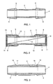
- Fig. 1 shows the housing 1 of an embodiment of the fuse according to the invention. The housing 1, which for instance consists of a suitable plastic material, has a substantially cylindrical shape. In this embodiment the inner diameter of the housing 1 is substantially constant throughout the length of the housing, but this is not a prerequisite. Optionally, the inner diameter may vary along the length of the housing, both in shape and in size. The housing 1 comprises a central
cylindrical portion 2 with an outer diameter that is substantially constant throughout, which centralcylindrical portion 2 spans more than half the length of the housing 1. On opposite ends in the vicinity of the ends of the housing 1 the centralcylindrical portion 2 merges with thickercylindrical portions cylinder portions cylindrical portion 2 to the thickercylindrical portions cylinder portion 3 is theconical end portion 5 extending towards the end of the housing 1 and adjacent to thecylinder portion 4 is theconical end portion 6 extending towards the opposite end of the housing 1. The outer diameter of theconical end portions cylindrical portion 2 of the housing 1. - A housing as shown in Fig. 1 is particularly suitable for a fuse of the miniature or subminiature type, as descridgeed in the above-mentioned European Patent Application 0,199,401. The housing may likewise consist of a plastic material with ablative properties, as is explained in said publication for the fuse descridgeed therein. As to the dimensions of the fuse according to the invention, it can be stated that in a housing 1 as shown in Fig. 1 and serving as an example, the total length of the housing 1 was approximately 18 mm, while the length of the central cylindrical portion was approximately 10 mm. The thicker
cylindrical portions conical end portions cylindrical portions - Fig. 2 shows an embodiment of the fuse according to the inventions wherein a housing 1 as descridgeed with reference to Fig. 1 is used. Arranged in the housing 1 is a
fuse element 7, here in the form of a simple fuse wire, extending diagonally across the housing 1. Theends fuse wire 7 are bent around the ends of the housing 1 and, at the outer side of the housing 1, clamped between (at one end) theconical end portion 5 and theend cap 10 of a suitable metal press-fitted onto theend portion 5 and the thickercylindrical portion 3, and (at the other end) theconical end portion 6 and theend cap 11, likewise of a suitable metal, press-fitted onto theconical end portion 6 and the thickercylindrical portion 4. A gas-tight sealing is accomplished in virtue of the fact that theend caps cylindrical portions - The
edge 12 of theend cap 10 is folded or turned towards the centralcylindrical portion 2 beyond the thickercylindrical portion 3. Similarly, theedge 13 of theend cap 11 is folded or turned towards the centralcylindrical portion 2 beyond the thickercylindrical portion 4. Thus, theend caps - At the bottom of the end cap 10 a
plate 14 of a suitable material, for instance metal, may be arranged for strengthening the construction. Similarly, asuitable plate 19 may be provided at the bottom of theend cap 11. - Suitable materials which can be used for the housing 1, the
end caps fuse element 7 are the same materials as those mentioned in the above-mentioned European Patent Application 0,199,401, and others. - Fig. 3 shows the housing 1 of another embodiment of the fuse according to the invention. This housing 1 consists for instance of a suitable plastic material and has a substantially cylindrical form. The inner diameter of the housing 1 is substantially constant throughout the length of the housing, although this is not a requisite, as has already been explained in the discussion of Fig. 1. In this embodiment, too, the housing 1 comprises a central
cylindrical portion 2 with an outer diameter that is substantially constant throughout, which centralcylindrical portion 2 spans more than half the length of the housing 1. On opposite ends of the centralcylindrical portion 2 of the housing 1grooves portion 2. Directly adjacent thegrooves cylindrical portion 2 merges with an initially thicker portion of the housing 1, formed (on the side of the groove 17) by theconvex ridge 15 and theconical portion 5, and (on the side of the groove 18) by theconvex ridge 16 and theconical portion 6. In the embodiment shown, onlyridges cylindrical portion 2 of the housing 1. The outer diameter of theconical end portions portion 2 at theridges - In a housing of the shape as shown in Fig. 3, as in the embodiment shown in Fig. 2, the end caps can be press-fitted over the conical ends, enabling a gas-tight sealing to be accomplished. Preferably, the inner diameter of the end caps to be used will to that end be smaller than the greatest diameter of the
ridges convex ridges grooves
Claims (5)
Applications Claiming Priority (2)
| Application Number | Priority Date | Filing Date | Title |
|---|---|---|---|
| NL8902572A NL8902572A (en) | 1989-10-17 | 1989-10-17 | MELT SAFETY. |
| NL8902572 | 1989-10-17 |
Publications (2)
| Publication Number | Publication Date |
|---|---|
| EP0423897A1 true EP0423897A1 (en) | 1991-04-24 |
| EP0423897B1 EP0423897B1 (en) | 1995-08-09 |
Family
ID=19855469
Family Applications (1)
| Application Number | Title | Priority Date | Filing Date |
|---|---|---|---|
| EP19900202757 Expired - Lifetime EP0423897B1 (en) | 1989-10-17 | 1990-10-16 | Fuse |
Country Status (3)
| Country | Link |
|---|---|
| EP (1) | EP0423897B1 (en) |
| DE (1) | DE69021493T2 (en) |
| NL (1) | NL8902572A (en) |
Cited By (6)
| Publication number | Priority date | Publication date | Assignee | Title |
|---|---|---|---|---|
| WO1994003915A2 (en) * | 1992-08-10 | 1994-02-17 | Littelfuse, Inc. | Solderless cartridge fuse |
| GB2278743A (en) * | 1993-06-01 | 1994-12-07 | Soc Corp | Chip fuse |
| US6774760B2 (en) * | 2001-06-05 | 2004-08-10 | Cooper Technologies Company | Fuse element positioning body |
| US7417526B2 (en) | 2002-09-28 | 2008-08-26 | Wickmann-Werke Gmbh | Self-configuring component by means of arcing |
| US20110298577A1 (en) * | 2010-06-04 | 2011-12-08 | Littelfuse, Inc. | Fuse with counter-bore body |
| US11101093B2 (en) * | 2019-01-21 | 2021-08-24 | Littelfuse, Inc. | Fuses and methods of forming fuses |
Families Citing this family (1)
| Publication number | Priority date | Publication date | Assignee | Title |
|---|---|---|---|---|
| US9117615B2 (en) | 2010-05-17 | 2015-08-25 | Littlefuse, Inc. | Double wound fusible element and associated fuse |
Citations (8)
| Publication number | Priority date | Publication date | Assignee | Title |
|---|---|---|---|---|
| NL59893C (en) * | 1941-05-02 | 1900-01-01 | ||
| GB706206A (en) * | 1951-06-18 | 1954-03-24 | Revo Electric Co Ltd | Improvements connected with electric cartridge fuses |
| FR1364445A (en) * | 1963-07-24 | 1964-06-19 | Legrand Ets | Cartridge circuit breaker improvements |
| GB1474695A (en) * | 1974-09-27 | 1977-05-25 | Beswick Ltd K | Cartridge fuse-links |
| GB1562485A (en) * | 1976-11-01 | 1980-03-12 | Beswick Ltd K | Cartridge fuses |
| US4563809A (en) * | 1982-12-09 | 1986-01-14 | Littelfuse, Inc. | Fuse with centered fuse filament and method of making the same |
| EP0199401A1 (en) * | 1985-04-04 | 1986-10-29 | Littelfuse Tracor B.V. | Fuse |
| US4646053A (en) * | 1985-12-30 | 1987-02-24 | Gould Inc. | Electric fuse having welded fusible elements |
-
1989
- 1989-10-17 NL NL8902572A patent/NL8902572A/en not_active Application Discontinuation
-
1990
- 1990-10-16 EP EP19900202757 patent/EP0423897B1/en not_active Expired - Lifetime
- 1990-10-16 DE DE1990621493 patent/DE69021493T2/en not_active Expired - Fee Related
Patent Citations (8)
| Publication number | Priority date | Publication date | Assignee | Title |
|---|---|---|---|---|
| NL59893C (en) * | 1941-05-02 | 1900-01-01 | ||
| GB706206A (en) * | 1951-06-18 | 1954-03-24 | Revo Electric Co Ltd | Improvements connected with electric cartridge fuses |
| FR1364445A (en) * | 1963-07-24 | 1964-06-19 | Legrand Ets | Cartridge circuit breaker improvements |
| GB1474695A (en) * | 1974-09-27 | 1977-05-25 | Beswick Ltd K | Cartridge fuse-links |
| GB1562485A (en) * | 1976-11-01 | 1980-03-12 | Beswick Ltd K | Cartridge fuses |
| US4563809A (en) * | 1982-12-09 | 1986-01-14 | Littelfuse, Inc. | Fuse with centered fuse filament and method of making the same |
| EP0199401A1 (en) * | 1985-04-04 | 1986-10-29 | Littelfuse Tracor B.V. | Fuse |
| US4646053A (en) * | 1985-12-30 | 1987-02-24 | Gould Inc. | Electric fuse having welded fusible elements |
Cited By (12)
| Publication number | Priority date | Publication date | Assignee | Title |
|---|---|---|---|---|
| WO1994003915A2 (en) * | 1992-08-10 | 1994-02-17 | Littelfuse, Inc. | Solderless cartridge fuse |
| WO1994003915A3 (en) * | 1992-08-10 | 1994-04-28 | Littelfuse Inc | Solderless cartridge fuse |
| GB2278743A (en) * | 1993-06-01 | 1994-12-07 | Soc Corp | Chip fuse |
| GB2278743B (en) * | 1993-06-01 | 1997-05-14 | Soc Corp | Chip fuse |
| US5642090A (en) * | 1993-06-01 | 1997-06-24 | Soc Corporation | Chip fuse |
| US5726620A (en) * | 1993-06-01 | 1998-03-10 | Soc Corporation | Chip fuse |
| US6774760B2 (en) * | 2001-06-05 | 2004-08-10 | Cooper Technologies Company | Fuse element positioning body |
| US7417526B2 (en) | 2002-09-28 | 2008-08-26 | Wickmann-Werke Gmbh | Self-configuring component by means of arcing |
| US20110298577A1 (en) * | 2010-06-04 | 2011-12-08 | Littelfuse, Inc. | Fuse with counter-bore body |
| US9224564B2 (en) * | 2010-06-04 | 2015-12-29 | Littelfuse, Inc. | Fuse with counter-bore body |
| US11101093B2 (en) * | 2019-01-21 | 2021-08-24 | Littelfuse, Inc. | Fuses and methods of forming fuses |
| US11521818B2 (en) | 2019-01-21 | 2022-12-06 | Littelfuse, Inc. | Fuses and methods of forming fuses |
Also Published As
| Publication number | Publication date |
|---|---|
| DE69021493T2 (en) | 1996-02-01 |
| NL8902572A (en) | 1991-05-16 |
| EP0423897B1 (en) | 1995-08-09 |
| DE69021493D1 (en) | 1995-09-14 |
Similar Documents
| Publication | Publication Date | Title |
|---|---|---|
| CA1050592A (en) | Miniature plug-in fuse and method of making same | |
| EP0370572A1 (en) | Fuse | |
| US4344060A (en) | Enclosed plug-in fuse assembly | |
| US5975964A (en) | Female terminal fitting | |
| EP0657962B1 (en) | Terminal for high-voltage resistant electrical cable | |
| US4603278A (en) | Electric lamp with insulating base | |
| US4999751A (en) | Innovative structure of christmas light assembly | |
| EP0423897B1 (en) | Fuse | |
| EP0145192A3 (en) | Fusible electrical connector | |
| US4343529A (en) | Terminal block with self locking terminal | |
| EP0035378B1 (en) | Electrical connector | |
| US5681192A (en) | Male terminal metal fixture | |
| US4295076A (en) | Electric lamp with cementless attached base | |
| JPH08213063A (en) | Pressure contact joint connector | |
| US4056884A (en) | Method of making a miniature plug-in fuse | |
| AU708118B2 (en) | Connection structure and method for electric wire and terminal | |
| US5947774A (en) | Press-connecting connector | |
| CA1041151A (en) | Electron tube base and socket | |
| US5381070A (en) | Lamp base locking clip | |
| US4136923A (en) | Unitary hooded electrical contact | |
| US5695352A (en) | Female Terminal fitting | |
| US4849670A (en) | Electric lamp having a pinch supported in a sleeve-shared cap | |
| EP0599624B1 (en) | Lamp base inner shell | |
| US6102551A (en) | Christmas lamp assembly | |
| GB2062981A (en) | Miniature electric fuse |
Legal Events
| Date | Code | Title | Description |
|---|---|---|---|
| PUAI | Public reference made under article 153(3) epc to a published international application that has entered the european phase |
Free format text: ORIGINAL CODE: 0009012 |
|
| AK | Designated contracting states |
Kind code of ref document: A1 Designated state(s): BE CH DE FR GB IT LI LU NL |
|
| 17P | Request for examination filed |
Effective date: 19910925 |
|
| 17Q | First examination report despatched |
Effective date: 19930702 |
|
| RAP1 | Party data changed (applicant data changed or rights of an application transferred) |
Owner name: LITTELFUSE B.V. |
|
| GRAA | (expected) grant |
Free format text: ORIGINAL CODE: 0009210 |
|
| AK | Designated contracting states |
Kind code of ref document: B1 Designated state(s): BE CH DE FR GB IT LI LU NL |
|
| REF | Corresponds to: |
Ref document number: 69021493 Country of ref document: DE Date of ref document: 19950914 |
|
| ET | Fr: translation filed | ||
| ITF | It: translation for a ep patent filed |
Owner name: SOCIETA' ITALIANA BREVETTI S.P.A. |
|
| PLBE | No opposition filed within time limit |
Free format text: ORIGINAL CODE: 0009261 |
|
| STAA | Information on the status of an ep patent application or granted ep patent |
Free format text: STATUS: NO OPPOSITION FILED WITHIN TIME LIMIT |
|
| 26N | No opposition filed | ||
| PGFP | Annual fee paid to national office [announced via postgrant information from national office to epo] |
Ref country code: LU Payment date: 20001006 Year of fee payment: 11 |
|
| PGFP | Annual fee paid to national office [announced via postgrant information from national office to epo] |
Ref country code: FR Payment date: 20001010 Year of fee payment: 11 Ref country code: CH Payment date: 20001010 Year of fee payment: 11 |
|
| PGFP | Annual fee paid to national office [announced via postgrant information from national office to epo] |
Ref country code: GB Payment date: 20001013 Year of fee payment: 11 |
|
| PGFP | Annual fee paid to national office [announced via postgrant information from national office to epo] |
Ref country code: BE Payment date: 20001120 Year of fee payment: 11 |
|
| PGFP | Annual fee paid to national office [announced via postgrant information from national office to epo] |
Ref country code: DE Payment date: 20001221 Year of fee payment: 11 |
|
| PGFP | Annual fee paid to national office [announced via postgrant information from national office to epo] |
Ref country code: NL Payment date: 20001231 Year of fee payment: 11 |
|
| PG25 | Lapsed in a contracting state [announced via postgrant information from national office to epo] |
Ref country code: LU Free format text: LAPSE BECAUSE OF NON-PAYMENT OF DUE FEES Effective date: 20011016 Ref country code: GB Free format text: LAPSE BECAUSE OF NON-PAYMENT OF DUE FEES Effective date: 20011016 |
|
| PG25 | Lapsed in a contracting state [announced via postgrant information from national office to epo] |
Ref country code: BE Free format text: LAPSE BECAUSE OF NON-PAYMENT OF DUE FEES Effective date: 20011031 Ref country code: LI Free format text: LAPSE BECAUSE OF NON-PAYMENT OF DUE FEES Effective date: 20011031 Ref country code: CH Free format text: LAPSE BECAUSE OF NON-PAYMENT OF DUE FEES Effective date: 20011031 |
|
| REG | Reference to a national code |
Ref country code: GB Ref legal event code: IF02 |
|
| BERE | Be: lapsed |
Owner name: LITTELFUSE B.V. Effective date: 20011031 |
|
| PG25 | Lapsed in a contracting state [announced via postgrant information from national office to epo] |
Ref country code: NL Free format text: LAPSE BECAUSE OF NON-PAYMENT OF DUE FEES Effective date: 20020501 |
|
| GBPC | Gb: european patent ceased through non-payment of renewal fee |
Effective date: 20011016 |
|
| REG | Reference to a national code |
Ref country code: CH Ref legal event code: PL |
|
| PG25 | Lapsed in a contracting state [announced via postgrant information from national office to epo] |
Ref country code: FR Free format text: LAPSE BECAUSE OF NON-PAYMENT OF DUE FEES Effective date: 20020628 |
|
| NLV4 | Nl: lapsed or anulled due to non-payment of the annual fee |
Effective date: 20020501 |
|
| PG25 | Lapsed in a contracting state [announced via postgrant information from national office to epo] |
Ref country code: DE Free format text: LAPSE BECAUSE OF NON-PAYMENT OF DUE FEES Effective date: 20020702 |
|
| REG | Reference to a national code |
Ref country code: FR Ref legal event code: ST |
|
| PG25 | Lapsed in a contracting state [announced via postgrant information from national office to epo] |
Ref country code: IT Free format text: LAPSE BECAUSE OF NON-PAYMENT OF DUE FEES Effective date: 20051016 |