EP0423715A2 - Synchronisation de l'accès au réseau dans un système de communication à évasion de fréquence - Google Patents
Synchronisation de l'accès au réseau dans un système de communication à évasion de fréquence Download PDFInfo
- Publication number
- EP0423715A2 EP0423715A2 EP90119817A EP90119817A EP0423715A2 EP 0423715 A2 EP0423715 A2 EP 0423715A2 EP 90119817 A EP90119817 A EP 90119817A EP 90119817 A EP90119817 A EP 90119817A EP 0423715 A2 EP0423715 A2 EP 0423715A2
- Authority
- EP
- European Patent Office
- Prior art keywords
- frequency
- signals
- signal
- synchronization
- synchronizing
- Prior art date
- Legal status (The legal status is an assumption and is not a legal conclusion. Google has not performed a legal analysis and makes no representation as to the accuracy of the status listed.)
- Granted
Links
Images

Classifications
-
- H—ELECTRICITY
- H04—ELECTRIC COMMUNICATION TECHNIQUE
- H04B—TRANSMISSION
- H04B1/00—Details of transmission systems, not covered by a single one of groups H04B3/00 - H04B13/00; Details of transmission systems not characterised by the medium used for transmission
- H04B1/69—Spread spectrum techniques
- H04B1/713—Spread spectrum techniques using frequency hopping
- H04B1/7156—Arrangements for sequence synchronisation
-
- H—ELECTRICITY
- H04—ELECTRIC COMMUNICATION TECHNIQUE
- H04B—TRANSMISSION
- H04B1/00—Details of transmission systems, not covered by a single one of groups H04B3/00 - H04B13/00; Details of transmission systems not characterised by the medium used for transmission
- H04B1/69—Spread spectrum techniques
- H04B1/707—Spread spectrum techniques using direct sequence modulation
- H04B1/709—Correlator structure
-
- H—ELECTRICITY
- H04—ELECTRIC COMMUNICATION TECHNIQUE
- H04B—TRANSMISSION
- H04B1/00—Details of transmission systems, not covered by a single one of groups H04B3/00 - H04B13/00; Details of transmission systems not characterised by the medium used for transmission
- H04B1/69—Spread spectrum techniques
- H04B1/713—Spread spectrum techniques using frequency hopping
- H04B1/7156—Arrangements for sequence synchronisation
- H04B2001/71563—Acquisition
Definitions
- the field of the invention relates to communication systems, and in particular, to synchronization for entry to a frequency hopping communication network.
- Modem high frequency communication systems commonly utilize frequency hopping spread spectrum waveforms to achieve a high degree of resistance to jamming.
- the frequency hopping waveform must hop quickly among many frequencies in a pseudo-random fashion.
- the pseudo-random frequency pattern is conventionally locked to the system timing since frequency hopping is essentially a time-frequency coded technique.
- the hop rate is made fast enough to prevent a jammer from tracking each hop.
- all units in the network must have the same timing.
- the network transceiver must initially synchronize with the rapid frequency hopping code of the network in order to communicate with the network.
- the transceiver must also maintain accurate timing with low time drift in order to maintain synchronization with the network.
- Some conventional synchronization techniques use long preambles which allow a receiver to correct its time.
- Other conventional synchronization techniques use shorter preambles, but still longer than the uncertainty time.
- these techniques use parallel processing of multiple channels.
- a feature of the present invention to provide a network synchronization arrangement for frequency hopping communication systems that corrects for large initial time errors, and that continuously or periodically updates system timing.
- Another feature of the invention is the provision of a network synchronization arrangement that does not use long preambles or special broadcasts.
- a network entry synchronization system wherein, when two transceivers A and B are communicating, a third unnetworked transceiver C extracts the network entry code pattern from the A-B transmission in order to enter the network.
- the invention employs hidden network entry synchronization codes.
- transceiver A transmits a known pattern as a hidden part of the communication which allows transceiver C to enter the A-B network.
- This hidden code pattern permits rapid synchronization and correction of large initial time errors, and permits correction of time drift from then on.
- the communication system thus provides for network entry synchronization without a conventional synchronizing preamble. Synchronization is facilitated by embedding synchronization codes in the frequency hopping sequence and, as a result, eliminating the conventional preamble.
- the frequency hopping communication system of the present invention com strictlyprises a transmitter section and a receiver section.
- the transmitter section includes a controller that is adapted to generate a sequence of control signals for each of a plurality of frames of communication information.
- the sequence of control signals includes at least one synchronization control signal (and typically two) intermixed with a plurality of data control signals.
- a frequency synthesizer is employed to convert the control signals into a sequence of pseudo-random frequency signals including a synchronization frequency signal and a plurality of data frequency signals.
- the transmitter section is coupled to the frequency synthesizer that is employed to transmit the synchronization frequency signal and the plurality of data frequency signals.
- the receiver section in accordance with the invention is implemented with a frequency detector which is adapted to generate a sequence of frequency signals in response to receipt of the synchronization frequency signal and the plurality of data frequency signals.
- a correlator is coupled to the frequency detector and is adapted to detect and correlate the synchronization frequency signal to generate a correlator signal. Detection of a peak in the correlator signal is indicative of syiichronization of the receiver section with the network.
- the correlator is adapted to control a synchronizing clock that maintains the correct timing to keep the receiver networked.
- the present invention initially synchronizes the transceiver for access to the network in the presence of relatively large time errors and maintains synchronization with the network in the presence of relatively high time drift rates. It is particularly appropriate for transceivers that are tolerant to jamming and for high performance modems.
- the present invention provides rapid initial network synchronization and continuous network resynchronization even in the presence of large initial time errors, large time drifts, jamming, multipath fading, and other communication conditions. It does not use a preamble, and does not require a special preamble broadcast.
- the present invention uses a small percentage of the frequency hopping waveform energy to provide continuous user time network entry so that any user can perform network synchronization whenever necessary. Thus, the synchronization process is continuous and reception is most likely, since the receiver can achieve synchronization at any time and repeat the process as many times as is necessary.
- a system of network entry synchronization which allows unnetworked transceivers having large initial time error to enter a network by aligning their timing with network time. Such a process is essential to establishing a frequency hopping communications network.
- the principles of the present invention may be applied to all frequency hopping networks, but they are particularly useful for protecting against communication network jamming, and multipath fading such as is found in the HF communication band.
- the present invention provides a system of network entry synchronization which uses a very short code pattern but still allows the receiver to correct for large initial time errors.
- the present invention also provides for continuous monitoring and correction of timing errors to prevent the timing of the transceivers from drifting apart.
- the key features of this invention are that time hopping of the code pattern not only transmits energy pulses to allow energy detection at the receiver, but also provides differential encoding of the time segment information to identify the transmitter timing segment.
- unit C when two units A and B are communicating, and a third unit C is attempting to enter the A-B network, unit C extracts the network entry code pattern from the A-B transmission in order to gain access to the network. That is, as a part of the communication between the two units A and B, unit A transmits a known pattern which allows unit C to enter the A-B network.
- FIG. 1 of the drawings there is shown a schematic diagram of a communications network 110 comprising three radio transceivers: user A 112, user B 113, and user C 114.
- user A 112 is communicating with user B 113 over a communications link 116 which is represented as bouncing off of a layer 118 which may be the ionosphere.
- User C 114 which desires to enter the network of user A 112 and user D 113, is monitoring the transmissions between user A 112 and user B 113 for the purpose of extracting the network entry code pattern from the A-B transmission.
- user A 112 generates a frequency hopping transmission having data signals interleaved or intermixed or embedded with synchronization signals. This may be considered to be preamble-less synchronization.
- User C 114 processes the synchronization signals to initially achieve synchronization and to maintain synchronization.
- the received synchronization codes are also utilized to continuously resynchronize user B 113 and the received data codes are for communication.
- New user C 114 that is not yet synchronized, and hence is not yet in the network, receives synchronization codes and data codes transmitted by user A 112.
- the synchronization codes are utilized to initially synchronize user C, but the received data codes are not utilized because user C 114 is not yet synchronized. However, after synchronization has been achieved, the received data codes are utilized by user C 114.
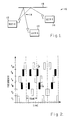
- FIG. 2 there is shown an example of interleaved data and synchronization codes.
- Certain frequencies in this example two frequencies f M , f N (shown in black in FIG. 2), are selected as synchronization frequencies and the remaining 62 frequencies are available for data encoding.
- FIG. 2 For simplicity, only a few of the 64 frequencies for data are shown in FIG. 2.
- a pseudo-random code sequence is shown for each frame in this example, which sequences from f2, to f1, to f k , to f M , to f N , and to f64.
- a synchronizing correlator (not shown) is tuned to a synchronizing code (f M , f N ) signature.
- a data correlator (not shown) is tuned to the data code (f2, f1, f k , and f64) signature.
- the synchronization frequency code and the data frequency code are interleaved and transmitted continuously.
- the synchronizing code is a very short code, less than the length of the uncertainty time compared with conventional preambles.
- the synchronization code is interleaved within the data transmission in contrast to conventional long preambles preceding the data transmission.
- the transmitter 300 comprises a digital controller 302, a synthesizer 314 coupled to the ROM 312, an RF transmitter 318 coupled to the output of the synthesizer 31 4, and an antenna 320 coupled to the output of the RF transmitter 318.
- the digital controller 302 includes a counter 310 and a read only memory (ROM) 312.
- the digital controller 302 is adapted to generate a pseudo-random code which is converted to a sequence of frequencies for transmission by the synthesizer 314.
- the counter 310 is adapted to generate sequential addresses 311 to the ROM 312.
- the ROM 312 stores a sequence of frequency codes having a pseudo-random signature and provides an output a pseudo-random signature signal 313.
- the signature signal 313 is coupled to the frequency synthesizer 314 which generates frequency signals 315 in response to the frequency codes in the signature signal 313.
- the frequency signals 315 are transmitted by the RF transmitter 318 and antenna 320 as a transmitter signal 322.
- Each frequency signal 315 may be modulated with data, such as with differential phase shift keyed (DPSK) modulation, for example.
- DPSK differential phase shift keyed
- the frequency signals 315 are also modulated by the synthesizer 314 in response to communication or data signals 324 applied thereto.
- the transmitter 300 described above is implemented with a ROM-based digital controller 302 having a pseudo-random sequence of frequency codes stored therein including interleaved data codes and synchronization codes, such as the frequency sequence shown in FIG. 2. Sequential accessing of the stored codes from the ROM 312 and generation of frequencies by the frequency synthesizer 314 in response thereto generates the frequency hopping pseudo-random signature for transmission as transmitter signal 322.
- a frequency hopping receiver 400 of the user C 114 for example, constructed in accordance with the present invention.
- This is a multiple channel receiver 400 having a separate channel for each synchronization frequency, of which two channels f M , f N of the 64 channels are shown.
- the receiver 400 comprises an RF front end 412, or preprocessor, which is coupled to two channels 405,406 that are adapted to preprocess the f M and f N frequency signals.
- Each channel 405,406 comprises a detector 414,415 whose respective outputs are coupled to a correlator 418,419, whose respective outputs are coupled to a synchronizing clock 422.
- the antenna 411 and RF front end 412 are adapted to receive and preprocess the transmitter signal 322 and generate a received signal 413 that is coupled to the multiple synchronization channels f M , f N .
- the f M frequency detector 4,14 and the f N frequency detector 415 respectively detect the f M and f N frequencies and generate f M and f N frequency detector signals 416,417.
- the respective outputs of the frequency detectors 414,415 comprise amplitude signals, indicative of the occurrence of a particular frequency component (f M , f N ), and modulation signals comprising the modulation on the detected frequency component.
- the amplitude signal may be a single bit digital signal or a multiple bit digital signal that is indicative of detection of the frequency component or magnitude of the frequency component.
- the modulation signal may be a single bit digital signal or a multiple bit digital signal that is indicative of detection or magnitude of the frequency component.
- the amplitude signal is a single bit digital signal that is in a one-state when the frequency component is detected and is in a zero-state when the frequency component is not detected.
- the modulation signal is a two phase DPSK single bit digital signal that is in a one-state when the DPSK modulation has a first phase condition and is in a zero-state when the DPSK modulation has a second phase condition.
- the f M correlator 418 for the f M frequency channel correlates the occurrences of the f M frequency detector signal 416 to determine when the occurrences are consistent with the signature for the f M frequency component.
- the f M correlator 418 generate an f M correlator output signal 420 in response to these detected occurrences.
- the f N frequency detector 415 detects the f N frequency and generates an f N frequency detector signal 417 in response thereto.
- the f N correlator 419 correlates the occurrences of the f N frequency detector signal 417 to determine when the occurrences are consistent with the signature for the f N frequency component and generates an f N correlator output signal 421 in response thereto.
- the correlator output signals 420, 421 synchronize the receiver 400, such as by resetting the synchronization clock 422.
- Correlator taps are typically placed having a spacing that is consistent with occurrence of the selected frequency components.
- the spacing of the f M frequency component in the transmitted signal should be consistent with the spacing of the taps from the shift register 510 for the f M channel.
- the spacing of the f N frequency component in the transmitted signal should be consistent with the spacing of the taps from the shift register for the f N channel.
- the correlator 418 comprises a shift register 510 which has two sections, namely a magnitude section and a modulation section.
- the shift register 510 has a plurality of taps 512, 525 for each section.
- the taps 525 of the modulation section are respectively coupled to a time decode circuit 524.
- the taps 512 of the magnitude section are coupled by way of respective summers 518 to a peak detector 520.
- the peak detector 520 is coupled to the time decode circuit 524 and is adapted to provide enabling signals thereto.
- the correlator 418 operates as a time domain correlator, for example, and is implemented by the shift register 510 having the plurality of spaced apart taps 512, 525.
- the f M frequency signal 416 comprising frequency magnitude detector signal 514 and modulation detector signal 522 are shifted through the shift register 510 and are provided at each of the taps 512, 525.
- a first magnitude signal is provided at a first magnitude signal tap 530 and a corresponding first modulation signal, is provided at a first modulation signal tap 531.
- a second magnitude signal is provided at a second magnitude signal tap 532 and a corresponding second modulation signal, is provided at a second modulation signal tap 533, and so forth for all taps in the shift register 510.
- the plurality of summers 518 are connected to the magnitude signal taps 512 to sample and sum energy that is delayed by the shift register 510. If the received signal timing and the tap spacing are aligned, the summed energy and the output signal 523 from the correlator taps 512 is large and hence a high correlation output signal 523 is generated. If the timing and the taps are not aligned tie energy at the correlator taps 512 is small due to the randomness of the hidden pattern and hence a low correlation output signal 523 is generated.
- the peak detector circuit 520 (or threshold detector circuit) detects a peak of the sum signal 523 that is indicative of a correlation peak and occurrence of synchronization and generates an output signal 521 to enable a time decode circuit 524 to resynchronize the clock 422 shown in FIG. 4.
- the time decode circuit 524 processes the modulation signals from the modulation taps 525 to generate resynchronization signals 420 to resynchronize the clock 422 of FIG. 4.
- synchronization code sequence using frequencies f M and f N is hidden in the time hopping sequence, and transmitted on a subset (two frequencies) of the full spectrum of frequencies (64 frequencies).
- synchronization codes may be easily changed on-line during system operation to use different frequencies in different pseudo-random signature sequences. This may be achieved by selecting different sequences in the ROM 312 with the address counter 310 in transmitter 300, and by selecting corresponding frequencies with the detectors 414,415 and corresponding signatures with the correlators 418,419 in the receiver 400.
- synchronization codes in accordance with the present invention are difficult to detect by an unauthorized user, are difficult to jam, and provide a significant degree of tolerance to fading.
- Programmable frequency detectors and programmable correlators 418, 419 permit taps to be changed to accommodate changes in the signatures of the synchronization signals.
- An array processor may be employed to perform a fast Fourier transform generating a spectrum of frequency signals, then to perform frequency domain correlation on each of the synchronization frequencies, and then to detect a peak condition to reset the clock as being indicative of synchronization.
- Programmability facilitates changing of synchronization frequencies and signatures on-line and hence provides greater tolerance to jammers.
Applications Claiming Priority (2)
| Application Number | Priority Date | Filing Date | Title |
|---|---|---|---|
| US07/422,257 US5121408A (en) | 1989-10-16 | 1989-10-16 | Synchronization for entry to a network in a frequency hopping communication system |
| US422257 | 1989-10-16 |
Publications (3)
| Publication Number | Publication Date |
|---|---|
| EP0423715A2 true EP0423715A2 (fr) | 1991-04-24 |
| EP0423715A3 EP0423715A3 (en) | 1992-08-12 |
| EP0423715B1 EP0423715B1 (fr) | 1996-07-17 |
Family
ID=23674066
Family Applications (1)
| Application Number | Title | Priority Date | Filing Date |
|---|---|---|---|
| EP90119817A Expired - Lifetime EP0423715B1 (fr) | 1989-10-16 | 1990-10-16 | Synchronisation de l'accès au réseau dans un système de communication à évasion de fréquence |
Country Status (4)
| Country | Link |
|---|---|
| US (1) | US5121408A (fr) |
| EP (1) | EP0423715B1 (fr) |
| DE (1) | DE69027830T2 (fr) |
| IL (1) | IL95819A (fr) |
Cited By (8)
| Publication number | Priority date | Publication date | Assignee | Title |
|---|---|---|---|---|
| FR2696602A1 (fr) * | 1992-10-02 | 1994-04-08 | Motorola Inc | Procédé et appareil permettant l'application de sauts de fréquence à une voie de signalisation dans un système de télécommunications. |
| EP0669068A1 (fr) * | 1993-08-25 | 1995-08-30 | Motorola, Inc. | Procede et appareil destines a fonctionner avec un canal de commande de saut de frequence dans un systeme de telecommunications |
| WO1999049591A1 (fr) * | 1998-03-23 | 1999-09-30 | Armstrong Satellite Research Limited | Systeme de telecommunication par satellite transmettant des paquets de donnees |
| US6359924B1 (en) | 1998-04-17 | 2002-03-19 | Alcatel | Wireless telecommunications system, base station and mobile user terminal that exchange radio signals according to a frequency hopping sequences |
| EP1202589A2 (fr) * | 1993-10-25 | 2002-05-02 | TELEFONAKTIEBOLAGET L M ERICSSON (publ) | Transfer d'information de sauts de fréquence dans un système cellulaire de communication radio |
| EP2003791A1 (fr) * | 2007-06-11 | 2008-12-17 | Broadcom Corporation | Synchronisation rapide et réception de données pour systèmes de communication sans fil de saut de fréquences |
| WO2014151516A1 (fr) * | 2013-03-15 | 2014-09-25 | Qualcomm Incorporated | Schéma de signalisation basse énergie pour des applications de clôture de balise |
| US11187783B2 (en) | 2018-08-14 | 2021-11-30 | Nxp B.V. | Radar systems and methods for operating radar systems |
Families Citing this family (68)
| Publication number | Priority date | Publication date | Assignee | Title |
|---|---|---|---|---|
| US7606575B2 (en) * | 1988-08-04 | 2009-10-20 | Broadcom Corporation | Remote radio data communication system with data rate switching |
| US20010050943A1 (en) * | 1989-08-03 | 2001-12-13 | Mahany Ronald L. | Radio frequency communication network having adaptive communication parameters |
| JP2850569B2 (ja) * | 1990-06-01 | 1999-01-27 | セイコーエプソン株式会社 | 選択呼出受信機 |
| US7558557B1 (en) * | 1991-11-12 | 2009-07-07 | Broadcom Corporation | Low-power messaging in a network supporting roaming terminals |
| US6374311B1 (en) * | 1991-10-01 | 2002-04-16 | Intermec Ip Corp. | Communication network having a plurality of bridging nodes which transmit a beacon to terminal nodes in power saving state that it has messages awaiting delivery |
| US7415548B2 (en) * | 1991-05-13 | 2008-08-19 | Broadcom Corporation | Communication network having a plurality of bridging nodes which transmits a polling message with backward learning technique to determine communication pathway |
| DE69233608T2 (de) * | 1991-10-01 | 2007-03-01 | Broadcom Corp., Irvine | Lokales Funkfrequenznetzwerk |
| US6407991B1 (en) * | 1993-05-06 | 2002-06-18 | Intermec Ip Corp. | Communication network providing wireless and hard-wired dynamic routing |
| US5517675A (en) * | 1991-10-04 | 1996-05-14 | Motorola, Inc. | Signal transmission synchronization in a communication system |
| US5533046A (en) * | 1992-10-08 | 1996-07-02 | Lund; Vanmetre | Spread spectrum communication system |
| US5396541A (en) * | 1992-10-23 | 1995-03-07 | At&T Corp. | Call handoff in a wireless telephone system |
| US7917145B2 (en) * | 1992-11-02 | 2011-03-29 | Broadcom Corporation | Radio frequency local area network |
| US5546429A (en) * | 1992-11-09 | 1996-08-13 | Motorola, Inc. | Frequency hopping code division multiple access radio communication unit |
| US5493698A (en) * | 1993-02-26 | 1996-02-20 | Hitachi Denshi Kabushiki Kaisha | Radio apparatus for simulataneously transmitting and receiving signals using a simple frequency |
| US5394433A (en) * | 1993-04-22 | 1995-02-28 | International Business Machines Corporation | Frequency hopping pattern assignment and control in multiple autonomous collocated radio networks |
| US5412687A (en) * | 1993-10-15 | 1995-05-02 | Proxim Incorporated | Digital communications equipment using differential quaternary frequency shift keying |
| US5442659A (en) * | 1993-10-22 | 1995-08-15 | International Business Machines Corporation | Radio communications system with fault tolerant frequency hopping synchronization |
| US6292508B1 (en) | 1994-03-03 | 2001-09-18 | Proxim, Inc. | Method and apparatus for managing power in a frequency hopping medium access control protocol |
| AU1974795A (en) | 1994-03-03 | 1995-09-18 | Proxim, Inc. | Frequency hopping medium access control protocol |
| US5446769A (en) * | 1994-03-04 | 1995-08-29 | Motorola, Inc. | Method for providing hand-offs in a frequency hopping communication system |
| US5511099A (en) * | 1994-03-30 | 1996-04-23 | Samsung Electronics Co., Ltd. | Passband sync block recovery |
| US5428637A (en) * | 1994-08-24 | 1995-06-27 | The United States Of America As Represented By The Secretary Of The Army | Method for reducing synchronizing overhead of frequency hopping communications systems |
| US5519717A (en) * | 1994-08-24 | 1996-05-21 | The United States Of America As Represented By The Secretary Of The Army | Method for time drift reduction of frequency hopping network clock |
| KR0142949B1 (ko) * | 1995-06-16 | 1998-08-01 | 김광호 | 이동국과 기지국간의 초기 동기 맞춤시간을 최소화한 주파수 운용 방법 |
| US5875179A (en) * | 1996-10-29 | 1999-02-23 | Proxim, Inc. | Method and apparatus for synchronized communication over wireless backbone architecture |
| US5910956A (en) * | 1996-11-05 | 1999-06-08 | Northrop Gruman Corporation | Random time interval generator |
| US5978379A (en) | 1997-01-23 | 1999-11-02 | Gadzoox Networks, Inc. | Fiber channel learning bridge, learning half bridge, and protocol |
| US5896425A (en) * | 1997-02-24 | 1999-04-20 | At&T Wireless Services Inc | Non-uniformly spaced tones for synchronization waveform |
| US5936972A (en) * | 1997-06-18 | 1999-08-10 | Motorola, Inc. | Syndrome-based channel quality or message structure determiner |
| US7224713B2 (en) * | 1998-04-09 | 2007-05-29 | Andrzej Partyka | Telemetry system with authentication |
| US6246713B1 (en) | 1998-06-08 | 2001-06-12 | Telefonaktiebolaget Lm Ericsson (Publ) | Frequency-hopping in a bandwidth-on-demand system |
| US6442190B1 (en) | 1998-11-10 | 2002-08-27 | The Board Of Regents Of The University Of Nebraska | Method and system for self-encoding a sequential string of data symbols for transmission via communication systems |
| US7430171B2 (en) | 1998-11-19 | 2008-09-30 | Broadcom Corporation | Fibre channel arbitrated loop bufferless switch circuitry to increase bandwidth without significant increase in cost |
| US6549784B1 (en) * | 1998-12-28 | 2003-04-15 | At&T Corp. | Method and apparatus for implementing measurement based dynamic frequency hopping in wireless communication systems |
| US6434184B2 (en) * | 1998-12-30 | 2002-08-13 | International Business Machines Corporation | Orthogonal frequency hopping using skip zones |
| US6897697B2 (en) * | 1999-06-28 | 2005-05-24 | Broadcom Corporation | Current-controlled CMOS circuit using higher voltage supply in low voltage CMOS process |
| US6911855B2 (en) * | 1999-06-28 | 2005-06-28 | Broadcom Corporation | Current-controlled CMOS circuit using higher voltage supply in low voltage CMOS process |
| US6424194B1 (en) * | 1999-06-28 | 2002-07-23 | Broadcom Corporation | Current-controlled CMOS logic family |
| US6424177B1 (en) * | 1999-06-28 | 2002-07-23 | Broadcom Corporation | Universal single-ended parallel bus |
| US6967974B1 (en) | 1999-09-30 | 2005-11-22 | Andrzej Partyka | Transmission of urgent messages in telemetry system |
| US6377792B1 (en) * | 1999-10-22 | 2002-04-23 | Motorola, Inc. | Method and apparatus for network-to-user verification of communication devices based on time |
| US6894975B1 (en) * | 2000-01-15 | 2005-05-17 | Andrzej Partyka | Synchronization and access of the nodes in a communications network |
| US6340899B1 (en) * | 2000-02-24 | 2002-01-22 | Broadcom Corporation | Current-controlled CMOS circuits with inductive broadbanding |
| US6925105B1 (en) | 2000-05-01 | 2005-08-02 | Andrzej Partyka | Overhead reduction in system for intermittent transmission |
| MXPA03000916A (es) * | 2000-08-01 | 2003-10-14 | Itron Inc | Sistema de espectro propagado de salto de frecuencia con rastreo de alta sensibilidad y sincronizacion con senales inestables de frecuencia. |
| US7209495B2 (en) | 2000-09-28 | 2007-04-24 | Andrzej Partyka | Urgent messages and power-up in frequency hopping system for intemittent transmission |
| US6864558B2 (en) | 2001-05-17 | 2005-03-08 | Broadcom Corporation | Layout technique for C3MOS inductive broadbanding |
| US7212534B2 (en) | 2001-07-23 | 2007-05-01 | Broadcom Corporation | Flow based congestion control |
| US6624699B2 (en) * | 2001-10-25 | 2003-09-23 | Broadcom Corporation | Current-controlled CMOS wideband data amplifier circuits |
| US7295555B2 (en) * | 2002-03-08 | 2007-11-13 | Broadcom Corporation | System and method for identifying upper layer protocol message boundaries |
| GB0206766D0 (en) * | 2002-03-22 | 2002-05-01 | Koninkl Philips Electronics Nv | Method of, and apparatus for, determining position |
| US7555013B2 (en) * | 2002-08-12 | 2009-06-30 | Harris Corporation | Method and system for the blind determination of frequency hopping system characteristics and synchronization thereto |
| US7934021B2 (en) * | 2002-08-29 | 2011-04-26 | Broadcom Corporation | System and method for network interfacing |
| US7346701B2 (en) * | 2002-08-30 | 2008-03-18 | Broadcom Corporation | System and method for TCP offload |
| US8180928B2 (en) * | 2002-08-30 | 2012-05-15 | Broadcom Corporation | Method and system for supporting read operations with CRC for iSCSI and iSCSI chimney |
| WO2004021626A2 (fr) * | 2002-08-30 | 2004-03-11 | Broadcom Corporation | Systeme et procede de manipulation de trames qui ne fonctionnent pas |
| US7313623B2 (en) * | 2002-08-30 | 2007-12-25 | Broadcom Corporation | System and method for TCP/IP offload independent of bandwidth delay product |
| US20040141616A1 (en) * | 2003-01-17 | 2004-07-22 | Ibm Corporation | Security object with encrypted, spread spectrum data communications |
| US7598811B2 (en) * | 2005-07-29 | 2009-10-06 | Broadcom Corporation | Current-controlled CMOS (C3MOS) fully differential integrated wideband amplifier/equalizer with adjustable gain and frequency response without additional power or loading |
| US7362174B2 (en) * | 2005-07-29 | 2008-04-22 | Broadcom Corporation | Current-controlled CMOS (C3MOS) wideband input data amplifier for reduced differential and common-mode reflection |
| KR100867319B1 (ko) * | 2005-08-08 | 2008-11-06 | 삼성전자주식회사 | 무선통신시스템에서 비동기 송신 검출 장치 및 방법 |
| US7598788B2 (en) * | 2005-09-06 | 2009-10-06 | Broadcom Corporation | Current-controlled CMOS (C3MOS) fully differential integrated delay cell with variable delay and high bandwidth |
| US7769074B2 (en) * | 2006-03-08 | 2010-08-03 | Renesas Technology Corporation | Detecting and synchronizing to frequency hopped packets |
| US8165101B2 (en) * | 2006-09-29 | 2012-04-24 | Microsoft Corporation | Automatic detection of hidden networks |
| US7852745B2 (en) | 2007-03-02 | 2010-12-14 | Signalink Technologies Inc. | Non-orthogonal frequency-division multiplexed communication through a non-linear transmission medium |
| CN103401583B (zh) * | 2013-06-25 | 2015-12-09 | 北京溢美四方软件技术有限公司 | 一种基于伪随机序列特征识别的时钟恢复及校准实现方法 |
| WO2019154518A1 (fr) * | 2018-02-12 | 2019-08-15 | Intel IP Corporation | Procédés et dispositifs de communications de dispositif à dispositif |
| EP3972141A1 (fr) * | 2020-09-22 | 2022-03-23 | Rohde & Schwarz GmbH & Co. KG | Réseau de communication et procédé de transmission de données et de la voix à synchronisation temporelle |
Citations (1)
| Publication number | Priority date | Publication date | Assignee | Title |
|---|---|---|---|---|
| GB2100944A (en) * | 1981-06-24 | 1983-01-06 | Racal Res Ltd | Synchronisation circuits |
Family Cites Families (3)
| Publication number | Priority date | Publication date | Assignee | Title |
|---|---|---|---|---|
| IL67379A (en) * | 1982-12-01 | 1985-11-29 | Tadiran Israel Elect Ind Ltd | Real-time frequency management system for hf communication networks |
| US4761796A (en) * | 1985-01-24 | 1988-08-02 | Itt Defense Communications | High frequency spread spectrum communication system terminal |
| US4677617A (en) * | 1985-10-04 | 1987-06-30 | Hughes Aircraft Company | Rapid frequency-hopping time synchronization |
-
1989
- 1989-10-16 US US07/422,257 patent/US5121408A/en not_active Expired - Lifetime
-
1990
- 1990-09-26 IL IL9581990A patent/IL95819A/en not_active IP Right Cessation
- 1990-10-16 DE DE69027830T patent/DE69027830T2/de not_active Expired - Lifetime
- 1990-10-16 EP EP90119817A patent/EP0423715B1/fr not_active Expired - Lifetime
Patent Citations (1)
| Publication number | Priority date | Publication date | Assignee | Title |
|---|---|---|---|---|
| GB2100944A (en) * | 1981-06-24 | 1983-01-06 | Racal Res Ltd | Synchronisation circuits |
Non-Patent Citations (1)
| Title |
|---|
| IEE PROCEEDINGS F. COMMUNICATIONS, RADAR & SIGNAL PROCESSING vol. 129, no. 3, June 1982, STEVENAGE,GB pages 213 - 222; P.J.MUNDAY & M.C.PINCHES: 'JAGUAR-V FREQUENCY-HOPPING RADIO SYSTEM' * |
Cited By (17)
| Publication number | Priority date | Publication date | Assignee | Title |
|---|---|---|---|---|
| FR2696602A1 (fr) * | 1992-10-02 | 1994-04-08 | Motorola Inc | Procédé et appareil permettant l'application de sauts de fréquence à une voie de signalisation dans un système de télécommunications. |
| EP0669068A1 (fr) * | 1993-08-25 | 1995-08-30 | Motorola, Inc. | Procede et appareil destines a fonctionner avec un canal de commande de saut de frequence dans un systeme de telecommunications |
| EP0669068A4 (fr) * | 1993-08-25 | 1999-05-06 | Motorola Inc | Procede et appareil destines a fonctionner avec un canal de commande de saut de frequence dans un systeme de telecommunications. |
| EP1202589A2 (fr) * | 1993-10-25 | 2002-05-02 | TELEFONAKTIEBOLAGET L M ERICSSON (publ) | Transfer d'information de sauts de fréquence dans un système cellulaire de communication radio |
| EP1202589A3 (fr) * | 1993-10-25 | 2003-05-07 | TELEFONAKTIEBOLAGET L M ERICSSON (publ) | Transfer d'information de sauts de fréquence dans un système cellulaire de communication radio |
| WO1999049591A1 (fr) * | 1998-03-23 | 1999-09-30 | Armstrong Satellite Research Limited | Systeme de telecommunication par satellite transmettant des paquets de donnees |
| US6359924B1 (en) | 1998-04-17 | 2002-03-19 | Alcatel | Wireless telecommunications system, base station and mobile user terminal that exchange radio signals according to a frequency hopping sequences |
| US8249130B2 (en) | 2007-06-11 | 2012-08-21 | Broadcom Corporation | Method and system for fast synchronization and data reception for frequency hopping wireless communication systems |
| EP2003791A1 (fr) * | 2007-06-11 | 2008-12-17 | Broadcom Corporation | Synchronisation rapide et réception de données pour systèmes de communication sans fil de saut de fréquences |
| US8831065B2 (en) | 2007-06-11 | 2014-09-09 | Broadcom Corporation | Method and system for fast synchronization and data reception for frequency hopping wireless communication systems |
| WO2014151516A1 (fr) * | 2013-03-15 | 2014-09-25 | Qualcomm Incorporated | Schéma de signalisation basse énergie pour des applications de clôture de balise |
| US8958455B2 (en) | 2013-03-15 | 2015-02-17 | Qualcomm Incorporated | Low energy signaling scheme for beacon fencing applications |
| CN105009469A (zh) * | 2013-03-15 | 2015-10-28 | 高通股份有限公司 | 用于信标围栏应用的低能量信令方案 |
| US9276630B2 (en) | 2013-03-15 | 2016-03-01 | Qualcomm Incorporated | Low energy signaling scheme for beacon fencing applications |
| JP2016519463A (ja) * | 2013-03-15 | 2016-06-30 | クアルコム,インコーポレイテッド | ビーコンフェンシングアプリケーションのための低エネルギー信号発信スキーム |
| CN105009469B (zh) * | 2013-03-15 | 2016-11-30 | 高通股份有限公司 | 用于信标围栏应用的低能量信令方案 |
| US11187783B2 (en) | 2018-08-14 | 2021-11-30 | Nxp B.V. | Radar systems and methods for operating radar systems |
Also Published As
| Publication number | Publication date |
|---|---|
| IL95819A0 (en) | 1991-06-30 |
| EP0423715B1 (fr) | 1996-07-17 |
| IL95819A (en) | 1994-08-26 |
| EP0423715A3 (en) | 1992-08-12 |
| DE69027830T2 (de) | 1996-11-28 |
| US5121408A (en) | 1992-06-09 |
| DE69027830D1 (de) | 1996-08-22 |
Similar Documents
| Publication | Publication Date | Title |
|---|---|---|
| EP0423715B1 (fr) | Synchronisation de l'accès au réseau dans un système de communication à évasion de fréquence | |
| US4532635A (en) | System and method employing two hop spread spectrum signal transmissions between small earth stations via a satellite and a large earth station and structure and method for synchronizing such transmissions | |
| US6700920B1 (en) | Frequency hopping system for intermittent transmission | |
| US4599732A (en) | Technique for acquiring timing and frequency synchronization for modem utilizing known (non-data) symbols as part of their normal transmitted data format | |
| US4280222A (en) | Receiver and correlator switching method | |
| US7224713B2 (en) | Telemetry system with authentication | |
| US5396515A (en) | Asymmetric spread spectrum correlator | |
| US5748687A (en) | Spreading code sequence acquisition system and method that allows fast acquisition in code division multiple access (CDMA) systems | |
| US5022047A (en) | Spread spectrum correlator | |
| US5151920A (en) | Radio LAN station with improved frame delimiter detection in a spread spectrum environment | |
| US7463709B2 (en) | Method and apparatus for generating a synchronization sequence in a spread spectrum communications transceiver | |
| USRE38523E1 (en) | Spreading code sequence acquisition system and method that allows fast acquisition in code division multiple access (CDMA) systems | |
| US7386026B1 (en) | Method and system for synchronizing and selectively addressing multiple receivers in a wireless, spread spectrum communication system | |
| US4752939A (en) | Hidden preamble for frequency hopped synchronization | |
| US4617674A (en) | Synchronizing system for spread spectrum transmissions between small earth stations by satellite via an intermediate hop to a large earth station | |
| US5719900A (en) | Dual-threshold spread spectrum correlator | |
| US4597087A (en) | Frequency hopping data communication system | |
| WO1996041437A1 (fr) | Systeme d'alarme sans fil | |
| US7301986B2 (en) | Frequency hopping system for intermittent transmission | |
| US7313164B1 (en) | Method and system for switching and detecting PN codes for fast acquisition of burst signal | |
| US6870875B1 (en) | Transmission of urgent messages in frequency hopping system for intermittent transmission | |
| EP1050116A1 (fr) | Systeme de transmission de donnees discretes avec des signaux de bande large a caractere de bruit | |
| US7831002B2 (en) | System, apparatus and method for synchronizing a spreading sequence transmitted during a plurality of time slots | |
| US6728293B1 (en) | Hopping pattern generation method in frequency hopping system for intermittent transmission | |
| US7209495B2 (en) | Urgent messages and power-up in frequency hopping system for intemittent transmission |
Legal Events
| Date | Code | Title | Description |
|---|---|---|---|
| PUAI | Public reference made under article 153(3) epc to a published international application that has entered the european phase |
Free format text: ORIGINAL CODE: 0009012 |
|
| AK | Designated contracting states |
Kind code of ref document: A2 Designated state(s): DE FR GB |
|
| PUAL | Search report despatched |
Free format text: ORIGINAL CODE: 0009013 |
|
| AK | Designated contracting states |
Kind code of ref document: A3 Designated state(s): DE FR GB |
|
| 17P | Request for examination filed |
Effective date: 19930202 |
|
| 17Q | First examination report despatched |
Effective date: 19950203 |
|
| GRAH | Despatch of communication of intention to grant a patent |
Free format text: ORIGINAL CODE: EPIDOS IGRA |
|
| GRAH | Despatch of communication of intention to grant a patent |
Free format text: ORIGINAL CODE: EPIDOS IGRA |
|
| GRAA | (expected) grant |
Free format text: ORIGINAL CODE: 0009210 |
|
| AK | Designated contracting states |
Kind code of ref document: B1 Designated state(s): DE FR GB |
|
| REF | Corresponds to: |
Ref document number: 69027830 Country of ref document: DE Date of ref document: 19960822 |
|
| ET | Fr: translation filed | ||
| PLBE | No opposition filed within time limit |
Free format text: ORIGINAL CODE: 0009261 |
|
| STAA | Information on the status of an ep patent application or granted ep patent |
Free format text: STATUS: NO OPPOSITION FILED WITHIN TIME LIMIT |
|
| 26N | No opposition filed | ||
| REG | Reference to a national code |
Ref country code: GB Ref legal event code: 732E |
|
| REG | Reference to a national code |
Ref country code: FR Ref legal event code: TP Ref country code: FR Ref legal event code: CD Ref country code: FR Ref legal event code: CA |
|
| REG | Reference to a national code |
Ref country code: GB Ref legal event code: IF02 |
|
| PGFP | Annual fee paid to national office [announced via postgrant information from national office to epo] |
Ref country code: DE Payment date: 20091026 Year of fee payment: 20 |
|
| PGFP | Annual fee paid to national office [announced via postgrant information from national office to epo] |
Ref country code: GB Payment date: 20091022 Year of fee payment: 20 Ref country code: FR Payment date: 20091110 Year of fee payment: 20 |
|
| REG | Reference to a national code |
Ref country code: GB Ref legal event code: PE20 Expiry date: 20101015 |
|
| PG25 | Lapsed in a contracting state [announced via postgrant information from national office to epo] |
Ref country code: GB Free format text: LAPSE BECAUSE OF EXPIRATION OF PROTECTION Effective date: 20101015 |
|
| PG25 | Lapsed in a contracting state [announced via postgrant information from national office to epo] |
Ref country code: DE Free format text: LAPSE BECAUSE OF EXPIRATION OF PROTECTION Effective date: 20101016 |