EP0422685A2 - Photoelectric switch - Google Patents
Photoelectric switch Download PDFInfo
- Publication number
- EP0422685A2 EP0422685A2 EP90119696A EP90119696A EP0422685A2 EP 0422685 A2 EP0422685 A2 EP 0422685A2 EP 90119696 A EP90119696 A EP 90119696A EP 90119696 A EP90119696 A EP 90119696A EP 0422685 A2 EP0422685 A2 EP 0422685A2
- Authority
- EP
- European Patent Office
- Prior art keywords
- light
- unit
- projecting unit
- receiving
- receiving unit
- Prior art date
- Legal status (The legal status is an assumption and is not a legal conclusion. Google has not performed a legal analysis and makes no representation as to the accuracy of the status listed.)
- Granted
Links
Images


Classifications
-
- G—PHYSICS
- G01—MEASURING; TESTING
- G01V—GEOPHYSICS; GRAVITATIONAL MEASUREMENTS; DETECTING MASSES OR OBJECTS; TAGS
- G01V8/00—Prospecting or detecting by optical means
- G01V8/10—Detecting, e.g. by using light barriers
- G01V8/12—Detecting, e.g. by using light barriers using one transmitter and one receiver
Definitions
- the present invention relates to a so-called transmissive-type photoelectric switch composed of a light-projecting unit and a light-receiving unit, the light-receiving unit being installed away from the light-projecting unit so as to receive light projected by the light-projecting unit.
- a transmissive-type photoelectric switch composed of a light-projecting unit and a light-receiving unit
- light projected from a light-emitting element of the light-projecting unit is received by a light-receiving element of the light-receiving unit and a signal representing a presence of an object is generated when the projected light is shut off by the object.
- the prior-art light-receiving unit therefore, at least a part of a top board of the unit body is formed by a transparent plate and further an operation display lamp (a light-emitting element) is arranged inside this transparent plate so as to be turned on only when the light-receiving element receives the projected light. Accordingly, it is possible to install the light-projecting unit and the light-receiving units at two accurate opposing positions, respectively by visually confirming the turn-on status of the operation display lamp, whenever the light-projecting unit and the light-receiving unit are aligned with each other.
- an operation display lamp a light-emitting element
- the display lamp is arranged on the top board of the unit body in such a way that the display lamp emits light toward a direction perpendicular to the optical axis of the light projected from the light-projecting unit, the turn-on status of the operation display lamp can be checked mainly on the side of the light-receiving unit.
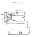
- the same applicant has already proposed a light-receiving unit as shown in Fig.7, by which it is possible to readily confirm the optical axis alignment condition on the light-projecting unit side, even if the distance between the light-projecting unit and the light-receiving unit is relatively long.
- the top board of a unit body 51 is formed of a transparent plate 52; a first operation display lamp (a light-emitting element) 53 is arranged inside of the transparent plate 52; an aperture is formed at a front end portion of the unit body 51; and a first convex lens 54 and a second convex lens 55 are mounted in the aperture.
- a light-receiving element 56 is located at a focus position of the first lens 54 and a second operation display lamp (light-emitting element) 57 is located at a focus position of the second lens 55.
- a circuit board 58 on which various electronic parts are mounted is fixed within the unit body 51. The light-receiving element 56, the first operation display lamp 53 and the second operation display lamp 57 are all electrically connected to this circuit board 58.
- both the first operation display lamp 53 and the second operation display lamp 57 turn on simultaneously owing to the operation of electric circuits provided on the circuit board 58.
- the first operation display lamp 53 emits light in the direction perpendicular to the optical axis of the light projected from the light-projecting unit, and the second operation display lamp 57 emits light directly toward the light-projecting unit. Therefore, when the optical axis alignment is performed by moving the light-receiving unit relative to the fixed light-projecting unit, the optical axis alignment can be confirmed on the basis of the first operation display lamp 53.
- the optical axis alignment is performed by moving the light-projecting unit relative to the fixed light-receiving unit, the optical axis alignment can be confirmed on the basis of the second operation display lamp 57, even if the distance between the light-projecting unit and the light-receiving unit is long.
- the present invention provides a photoelectric switch having a light-projecting unit for projecting light and a light-receiving unit installable remote from the light-projecting unit so as to receive the light projected by said light-projecting unit, wherein said light-receiving unit comprises: a light-receiving optical system including a focusing lens disposed on a front surface of a unit body of the light-receiving unit and a light-receiving element disposed at a focus position of said focusing lens; and reflector means disposed in the vicinity of said focusing lens, for reflecting part of the light including visible light components and projected from said light-projecting unit, toward said light-projecting unit.
- a light-receiving optical system including a focusing lens disposed on a front surface of a unit body of the light-receiving unit and a light-receiving element disposed at a focus position of said focusing lens; and reflector means disposed in the vicinity of said focusing lens, for reflecting
- reflector means is disposed in the vicinity of a focusing lens mounted on a front surface of the light-receiving unit body.
- the reflector means is a retroreflector composed of a plurality of corner-cube prisms, for instance.
- Light including visible light components and projected from a light-projecting unit is allowed to be incident upon a light receiving portion (the focusing lens and its peripheral portion) of the light-receiving unit.
- Part of the projected light is focused through the focusing lens and then received by a light-receiving element. A part of the remaining projected light is reflected by the reflector means toward a light-projecting unit.
- the optical axis alignment when the optical axis alignment is required to be checked on the light-projecting unit side, it is possible to check whether the projected light is allowed to be correctly incident upon the light-receiving unit from the light-projecting unit side, because confirmed when the projected light correctly impinges upon the light-receiving unit. In other words, even if the distance between the light-projecting unit and the light-receiving unit is long, it is possible to align the optical axis of the light-projecting unit with that of the light-receiving unit on the light-projecting unit side.
- the optical axis alignment can be performed by providing the reflector means within the light-receiving unit, without complicating the structure thereof.
- the optical axis alignment from the light-projecting unit side can be easily confirmed on the basis of presence or absence of the light reflected from the reflector means provided on the light-receiving unit installed at such a position as to be opposed to the light-projecting unit. Therefore, it is possible to provide a low-costly transmissive-type photoelectric switch, because the two operation display lamps (light-emitting elements) and the lamp driving circuit therefor are both not required. Further, since the optimum optical axis alignment position or angle can be checked on the basis of the intensity of light reflected from the reflector means, the optical axes of the two units can be aligned with each other at the most stable positional relationship.
- Fig.1 is a cross-sectional view showing an embodiment of the light-receiving unit of the photoelectric switch according to the present invention.
- a transmissive-type photoelectric switch is generally composed of a light-receiving unit 1 and a light-projecting unit 3, as shown in Figs.4a and 4b, as described in further detail hereinbelow.
- the light-receiving unit 1 and the light-projecting unit 3 are opposingly installed an appropriate distance apart from each other. Light projected from a light emitting element 31 of the light-projecting unit 3 is always received by the light-receiving unit 1. The presence of a moving object can be detected when the projected light is shut off by the object moving through between the two units 1 and 3.
- the light-receiving unit 1 includes a unit body 11 formed with an upper surface wall including a transparent plate 12 and an operation display lamp (light-emitting element) 13 attached to the inner surface of the transparent plate 12. Further, the unit body 11 is formed with an aperture on the front surface thereof and a light-receiving optical part 2 including a convex condenser (focusing) lens 21 and a reflector 22 together is fitted to this aperture. A light-receiving element (phototransistor) 14 is located at a focus position of the condenser lens 21.
- the light-receiving element 14 and the operation display lamp (light-emitting diode) 13 are both electrically connected to a circuit board 15 on which various electronic parts are mounted, so that the operation display lamp 13 is turned on when the light-receiving element 14 receives the light projected from the light-emitting element 31 of the light-projecting unit 3 due to the operation of an electric circuit provided on the circuit board 15.
- Fig. 2a is an enlarged front view showing the light-receiving optical part (system) 2
- Fig.2b is a cross-sectional view showing the same.
- the light-receiving optical part 2 includes the condenser lens 21 and the reflector 22 formed integral with each other.
- the condenser lens 21 is formed on the upper half side and the reflector 22 is formed on the lower half side in this embodiment shown.
- the condenser lens 21 is a convex lens
- the reflector 22 is a retroreflecting plate (reflex-reflector) comprising a plurality of corner-cubes (reflecting elements) 22a so arranged that three reflecting plates of each corner-cube are placed at right angles with respect to each other.
- This reflector 22 reflects part of visible light projected by the light-projecting unit 3 toward the light-projecting unit 3.
- Fig. 3a is an enlarged front view showing another embodiment of the light-receiving optical part 2
- Fig.3b is a cross-sectional view showing the same.
- the condenser lens 21 is formed at the central portion thereof and the reflector (the retroreflector plate) 22 is arranged outside the condenser lens 21 so as to surround the condenser lens 21. In this embodiment, it is possible to more accurately reflect the projected light toward the light-projecting unit 3.
- Figs.4a and 4b show another embodiment of the light-receiving unit 1.
- the condenser lens and the reflector are arranged separately from each other, being different from the embodiment shown in Fig.l in which the condenser lens 21 and the reflector 22 are formed integral with each other.
- the light-receiving optical part 2 includes an upper condenser lens 21, a lower transparent plate 23, and a tape-shaped reflector (retroreflector) 22a removably bonded onto the surface of the transparent plate 23.
- the retroreflector 22a can be removed easily, it is possible to readily replace an old or broken retroreflector 22a with a new one.
- Fig.5 is a cross-sectional view showing a still another embodiment of the light-receiving unit 1.
- the reflector part is composed of a condenser lens 24 and a concave mirror 25.
- the light-receiving optical part 2 includes a condenser lens 21 and a convex condenser lens 24 formed integral with each other.
- a light-receiving element 14 is located at the focus position of the condenser lens 21, and the concave mirror 25 is located at the focus position of the convex condenser lens 24.
- the retroreflective reflector is composed of the convex condenser lens 24 and the concave mirror 25 to reflect part of the visible light projected from the light-projecting unit 3 by the concave mirror 25, and further to return a beam collimated through the convex condenser lens 24 toward the light-projecting unit 3.
- Fig.6 is a cross-sectional view showing still another embodiment of the light-receiving unit 1.
- the reflector of this embodiment is the same as the above-mentioned embodiment shown in Fig.5 in that the retroreflective reflector is composed of the convex condenser lens 24 and the concave mirror 25.
- the concave mirror 25 is formed or arranged in such a way that the optical axis thereof is a little tilted with respect to that of the condenser lens 24. Therefore, the light incident upon the convex condenser lens 24 is reflected by a concave mirror 25, and then projected as a collimated beam through the convex condenser lens 24 obliquely upward with respect to the light incident upon the convex condenser lens 24.
- the reflected light can be confirmed visually from behind and a little upward away from the light-projecting unit 3, there exists an advantage such that the reflected light can be more easily confirmed on the light-projecting unit side. Since any given reflection directivity can be obtained by freely determining the radius of curvature or the tilt angle of the concave mirror 25, it is possible to eliminate a harmful influence of parallax (between the light-projecting unit and the worker) upon the visual confirmation of the reflected light, thus enabling the more accurate optical axis alignment work.
- the optical axis alignment when the optical axis alignment is performed by adjustably moving the light-receiving unit 1 relative to the fixed light-projecting unit 3, the optical axis alignment can be confirmed on the basis of the turn-on status of the operation display lamp 13 as is conventional.
- the reflector i.e. retroreflector plate 22
- the visible light beam projected from the light-projecting unit 3 is allowed to impinge upon the light-receiving optical part 2 of the light-receiving unit 1.
- part of the projected visible light is focused through the condenser lens 21 of the light-receiving optical part 2 and then allowed to be incident upon the light-receiving element 14.
- part of the projected light is reflected by the retroreflector 22 toward the light-projecting unit 3. Therefore, it is possible to confirm the light reflected by the retroreflector 22, when the projected visible light is allowed to impinge upon the optical light-receiving optical part 2, by seeing the light-receiving unit 1 from behind the light-projecting unit 3 installed a long distance away from the light-receiving unit 1.
Abstract
Description
- The present invention relates to a so-called transmissive-type photoelectric switch composed of a light-projecting unit and a light-receiving unit, the light-receiving unit being installed away from the light-projecting unit so as to receive light projected by the light-projecting unit.
- In a transmissive-type photoelectric switch composed of a light-projecting unit and a light-receiving unit, light projected from a light-emitting element of the light-projecting unit is received by a light-receiving element of the light-receiving unit and a signal representing a presence of an object is generated when the projected light is shut off by the object. To accurately detect an object, it is indispensable to install the light-projecting unit and light-receiving unit so as to be aligned with and opposed to each other. In the prior-art light-receiving unit, therefore, at least a part of a top board of the unit body is formed by a transparent plate and further an operation display lamp (a light-emitting element) is arranged inside this transparent plate so as to be turned on only when the light-receiving element receives the projected light. Accordingly, it is possible to install the light-projecting unit and the light-receiving units at two accurate opposing positions, respectively by visually confirming the turn-on status of the operation display lamp, whenever the light-projecting unit and the light-receiving unit are aligned with each other.
- However, since the display lamp is arranged on the top board of the unit body in such a way that the display lamp emits light toward a direction perpendicular to the optical axis of the light projected from the light-projecting unit, the turn-on status of the operation display lamp can be checked mainly on the side of the light-receiving unit.
- Accordingly, when the distance between the light-projecting unit and the light-receiving unit is relatively short, it is possible to check the turn-on status of the operation display lamp from the side of the light-projecting unit. However, when the distance between the two units is long, there exists a problem in that it is difficult to check the turn-on status of the operation display lamp on the side of the light-projecting unit.
- To overcome the above-mentioned problem, the same applicant has already proposed a light-receiving unit as shown in Fig.7, by which it is possible to readily confirm the optical axis alignment condition on the light-projecting unit side, even if the distance between the light-projecting unit and the light-receiving unit is relatively long.
- In the prior-art light-receiving unit shown in Fig.7, the top board of a
unit body 51 is formed of atransparent plate 52; a first operation display lamp (a light-emitting element) 53 is arranged inside of thetransparent plate 52; an aperture is formed at a front end portion of theunit body 51; and a firstconvex lens 54 and a secondconvex lens 55 are mounted in the aperture. A light-receivingelement 56 is located at a focus position of thefirst lens 54 and a second operation display lamp (light-emitting element) 57 is located at a focus position of thesecond lens 55. Further, acircuit board 58 on which various electronic parts are mounted is fixed within theunit body 51. The light-receivingelement 56, the firstoperation display lamp 53 and the secondoperation display lamp 57 are all electrically connected to thiscircuit board 58. - In the above-mentioned light-receiving unit, when the light-receiving
element 56 of the light-receiving unit receives light projected from the light-projecting unit, both the firstoperation display lamp 53 and the secondoperation display lamp 57 turn on simultaneously owing to the operation of electric circuits provided on thecircuit board 58. The firstoperation display lamp 53 emits light in the direction perpendicular to the optical axis of the light projected from the light-projecting unit, and the secondoperation display lamp 57 emits light directly toward the light-projecting unit. Therefore, when the optical axis alignment is performed by moving the light-receiving unit relative to the fixed light-projecting unit, the optical axis alignment can be confirmed on the basis of the firstoperation display lamp 53. On the other hand, when the optical axis alignment is performed by moving the light-projecting unit relative to the fixed light-receiving unit, the optical axis alignment can be confirmed on the basis of the secondoperation display lamp 57, even if the distance between the light-projecting unit and the light-receiving unit is long. - In the above-mentioned light-receiving unit (as shown in Fig.7) of the transmissive-type photoelectric switch proposed by the same applicant, since the second operation display lamp is additionally provided, there exists an advantage such that it is possible to easily confirm the optical axis alignment on the light-projecting unit side, even if the distance between the two opposing units is relatively long.
- In this prior-art light-receiving unit of the transmissive-type photoelectric switch, however, there exists a disadvantage such that not only two operation display lamps (light emitting elements) are required, but also a complicated and high costly driving circuits are necessary.
- With these problems in mind, therefore, it is the object of the present invention to provide a photoelectric switch, which can simplify the construction of the light-receiving unit and permit the optical axis alignment between the light-projecting unit and a light-receiving unit to be confirmed by visual check, even when the distance between the two units is relatively long.
- To achieve the above-mentioned object, the present invention provides a photoelectric switch having a light-projecting unit for projecting light and a light-receiving unit installable remote from the light-projecting unit so as to receive the light projected by said light-projecting unit, wherein said light-receiving unit comprises: a light-receiving optical system including a focusing lens disposed on a front surface of a unit body of the light-receiving unit and a light-receiving element disposed at a focus position of said focusing lens; and reflector means disposed in the vicinity of said focusing lens, for reflecting part of the light including visible light components and projected from said light-projecting unit, toward said light-projecting unit.
- According to the present invention, reflector means is disposed in the vicinity of a focusing lens mounted on a front surface of the light-receiving unit body. The reflector means is a retroreflector composed of a plurality of corner-cube prisms, for instance. Light including visible light components and projected from a light-projecting unit is allowed to be incident upon a light receiving portion (the focusing lens and its peripheral portion) of the light-receiving unit. Part of the projected light is focused through the focusing lens and then received by a light-receiving element. A part of the remaining projected light is reflected by the reflector means toward a light-projecting unit. Therefore, when the optical axis alignment is required to be checked on the light-projecting unit side, it is possible to check whether the projected light is allowed to be correctly incident upon the light-receiving unit from the light-projecting unit side, because confirmed when the projected light correctly impinges upon the light-receiving unit. In other words, even if the distance between the light-projecting unit and the light-receiving unit is long, it is possible to align the optical axis of the light-projecting unit with that of the light-receiving unit on the light-projecting unit side. In addition, the optical axis alignment can be performed by providing the reflector means within the light-receiving unit, without complicating the structure thereof.
- As described above, according to the present invention, the optical axis alignment from the light-projecting unit side can be easily confirmed on the basis of presence or absence of the light reflected from the reflector means provided on the light-receiving unit installed at such a position as to be opposed to the light-projecting unit. Therefore, it is possible to provide a low-costly transmissive-type photoelectric switch, because the two operation display lamps (light-emitting elements) and the lamp driving circuit therefor are both not required. Further, since the optimum optical axis alignment position or angle can be checked on the basis of the intensity of light reflected from the reflector means, the optical axes of the two units can be aligned with each other at the most stable positional relationship.
-
- Fig.1 is a cross-sectional view showing an embodiment of the light-receiving unit of the transmissive-type photoelectric switch according to the present invention;
- Fig. 2a is a front view showing a light-receiving optical part;
- Fig.2b is a cross-sectional view of Fig. 2a;
- Fig.3a is a front view showing another light-receiving optical part;
- Fig.3b is a cross-sectional view of Fig. 3a;
- Fig.4a is a side view showing a light-projecting unit;
- Fig.4b is a side, partially broken view showing another embodiment of the light-receiving unit;
- Fig.5 is a side, partially broken view showing another embodiment of the light-receiving unit;
- Fig.6 is a side, partially broken view showing still another embodiment of the light-receiving unit; and
- Fig.7 is a side, partially broken view showing a prior-art light-receiving unit of the transmissive-type photoelectric switch.
- Fig.1 is a cross-sectional view showing an embodiment of the light-receiving unit of the photoelectric switch according to the present invention.
- A transmissive-type photoelectric switch is generally composed of a light-
receiving unit 1 and a light-projecting unit 3, as shown in Figs.4a and 4b, as described in further detail hereinbelow. The light-receivingunit 1 and the light-projecting unit 3 are opposingly installed an appropriate distance apart from each other. Light projected from alight emitting element 31 of the light-projecting unit 3 is always received by the light-receivingunit 1. The presence of a moving object can be detected when the projected light is shut off by the object moving through between the twounits - In Fig. 1, the light-
receiving unit 1 includes aunit body 11 formed with an upper surface wall including atransparent plate 12 and an operation display lamp (light-emitting element) 13 attached to the inner surface of thetransparent plate 12. Further, theunit body 11 is formed with an aperture on the front surface thereof and a light-receivingoptical part 2 including a convex condenser (focusing)lens 21 and areflector 22 together is fitted to this aperture. A light-receiving element (phototransistor) 14 is located at a focus position of thecondenser lens 21. The light-receivingelement 14 and the operation display lamp (light-emitting diode) 13 are both electrically connected to acircuit board 15 on which various electronic parts are mounted, so that theoperation display lamp 13 is turned on when the light-receivingelement 14 receives the light projected from the light-emittingelement 31 of the light-projecting unit 3 due to the operation of an electric circuit provided on thecircuit board 15. - Fig. 2a is an enlarged front view showing the light-receiving optical part (system) 2, and Fig.2b is a cross-sectional view showing the same. The light-receiving
optical part 2 includes thecondenser lens 21 and thereflector 22 formed integral with each other. Thecondenser lens 21 is formed on the upper half side and thereflector 22 is formed on the lower half side in this embodiment shown. As depicted in Fig.2b, thecondenser lens 21 is a convex lens, and thereflector 22 is a retroreflecting plate (reflex-reflector) comprising a plurality of corner-cubes (reflecting elements) 22a so arranged that three reflecting plates of each corner-cube are placed at right angles with respect to each other. Thisreflector 22 reflects part of visible light projected by the light-projectingunit 3 toward the light-projecting unit 3. - Fig. 3a is an enlarged front view showing another embodiment of the light-receiving
optical part 2, and Fig.3b is a cross-sectional view showing the same. In this embodiment, thecondenser lens 21 is formed at the central portion thereof and the reflector (the retroreflector plate) 22 is arranged outside thecondenser lens 21 so as to surround thecondenser lens 21. In this embodiment, it is possible to more accurately reflect the projected light toward the light-projectingunit 3. - Figs.4a and 4b show another embodiment of the light-receiving
unit 1. In this embodiment, the condenser lens and the reflector are arranged separately from each other, being different from the embodiment shown in Fig.l in which thecondenser lens 21 and thereflector 22 are formed integral with each other. In more detail, the light-receivingoptical part 2 includes anupper condenser lens 21, a lowertransparent plate 23, and a tape-shaped reflector (retroreflector) 22a removably bonded onto the surface of thetransparent plate 23. In this embodiment, since theretroreflector 22a can be removed easily, it is possible to readily replace an old orbroken retroreflector 22a with a new one. - Fig.5 is a cross-sectional view showing a still another embodiment of the light-receiving
unit 1. In this embodiment, the reflector part is composed of acondenser lens 24 and aconcave mirror 25. In more detail, the light-receivingoptical part 2 includes acondenser lens 21 and aconvex condenser lens 24 formed integral with each other. A light-receivingelement 14 is located at the focus position of thecondenser lens 21, and theconcave mirror 25 is located at the focus position of theconvex condenser lens 24. The retroreflective reflector is composed of theconvex condenser lens 24 and theconcave mirror 25 to reflect part of the visible light projected from the light-projectingunit 3 by theconcave mirror 25, and further to return a beam collimated through theconvex condenser lens 24 toward the light-projectingunit 3. - In this embodiment, it is possible to use a twin-lens optical system for a so-called reflective-type photoelectric switch as the light-receiving optical part (reflector) 2 without any modification. Therefore, it is possible to construct a low-costly retroreflective reflector without preparing new additional members or parts.
- Fig.6 is a cross-sectional view showing still another embodiment of the light-receiving
unit 1. - The reflector of this embodiment is the same as the above-mentioned embodiment shown in Fig.5 in that the retroreflective reflector is composed of the
convex condenser lens 24 and theconcave mirror 25. In this embodiment, however, theconcave mirror 25 is formed or arranged in such a way that the optical axis thereof is a little tilted with respect to that of thecondenser lens 24. Therefore, the light incident upon theconvex condenser lens 24 is reflected by aconcave mirror 25, and then projected as a collimated beam through theconvex condenser lens 24 obliquely upward with respect to the light incident upon theconvex condenser lens 24. Therefore, since the reflected light can be confirmed visually from behind and a little upward away from the light-projectingunit 3, there exists an advantage such that the reflected light can be more easily confirmed on the light-projecting unit side. Since any given reflection directivity can be obtained by freely determining the radius of curvature or the tilt angle of theconcave mirror 25, it is possible to eliminate a harmful influence of parallax (between the light-projecting unit and the worker) upon the visual confirmation of the reflected light, thus enabling the more accurate optical axis alignment work. - In the transmissive-type photoelectric switch as described above, when the optical axis alignment is performed by adjustably moving the light-receiving
unit 1 relative to the fixed light-projectingunit 3, the optical axis alignment can be confirmed on the basis of the turn-on status of theoperation display lamp 13 as is conventional. In contrast, when the optical axis alignment is made by adjustably moving the light-projectingunit 3 relative to the fixed light-receivingunit 1, the reflector (i.e. retroreflector plate 22) disposed so as to be opposed to the light-projectingunit 3 is utilized. That is, the visible light beam projected from the light-projectingunit 3 is allowed to impinge upon the light-receivingoptical part 2 of the light-receivingunit 1. Under these conditions, part of the projected visible light is focused through thecondenser lens 21 of the light-receivingoptical part 2 and then allowed to be incident upon the light-receivingelement 14. At the same time, part of the projected light is reflected by theretroreflector 22 toward the light-projectingunit 3. Therefore, it is possible to confirm the light reflected by theretroreflector 22, when the projected visible light is allowed to impinge upon the optical light-receivingoptical part 2, by seeing the light-receivingunit 1 from behind the light-projectingunit 3 installed a long distance away from the light-receivingunit 1. On the other hand, when the projected visible light is not allowed to impinge upon the light-receivingoptical part 2, there exists no light reflected from theretroreflector 22. Therefore, it is possible to check whether the light projected from the light-projectingunit 3 is correctly allowed to be incident upon the light-receivingoptical part 2 on the light-projecting unit side. Further, in this case, it is possible to achieve the optimum optical axis alignment work, by aligning the axis of the light-projectingunit 3 with that of the light-receivingunit 1 so that the intensity of the light reflected by theretroreflector 22 becomes the maximum value.
Claims (7)
a light-receiving optical system including a focusing lens (21) disposed on a front surface of a unit body (11) of the light-receiving unit and a light-receiving element (14) disposed at a focus position of said focusing lens; and
reflector means (22, 22a, 24, 25) disposed in the vicinity of said focusing lens, for reflecting part of the light including visible light components and projected from said light-projecting unit, toward said light-projecting unit.
Applications Claiming Priority (2)
| Application Number | Priority Date | Filing Date | Title |
|---|---|---|---|
| JP12031089U JPH0374440U (en) | 1989-07-18 | 1989-10-13 | |
| JP120310/89U | 1989-10-13 |
Publications (3)
| Publication Number | Publication Date |
|---|---|
| EP0422685A2 true EP0422685A2 (en) | 1991-04-17 |
| EP0422685A3 EP0422685A3 (en) | 1992-09-16 |
| EP0422685B1 EP0422685B1 (en) | 1995-02-01 |
Family
ID=14783075
Family Applications (1)
| Application Number | Title | Priority Date | Filing Date |
|---|---|---|---|
| EP90119696A Expired - Lifetime EP0422685B1 (en) | 1989-10-13 | 1990-10-15 | Photoelectric switch |
Country Status (3)
| Country | Link |
|---|---|
| EP (1) | EP0422685B1 (en) |
| AT (1) | ATE118101T1 (en) |
| DE (1) | DE69016560T2 (en) |
Cited By (4)
| Publication number | Priority date | Publication date | Assignee | Title |
|---|---|---|---|---|
| AU659068B3 (en) * | 1994-04-11 | 1995-05-04 | Peng Heng Hsiu | Full automatic, photo inductor-controlled time switch |
| DE19812304C2 (en) * | 1997-03-26 | 2000-05-25 | Captron Elect Gmbh | Electronic sending and receiving device |
| EP1394504A1 (en) * | 2002-08-30 | 2004-03-03 | Sick AG | Light curtain or light barrier |
| DE202020104230U1 (en) | 2020-07-22 | 2021-10-26 | Sick Ag | System for adjusting a light transmitter |
Families Citing this family (1)
| Publication number | Priority date | Publication date | Assignee | Title |
|---|---|---|---|---|
| DE20317622U1 (en) | 2003-11-14 | 2004-02-12 | Sick Ag | Photoelectric barrier |
Citations (3)
| Publication number | Priority date | Publication date | Assignee | Title |
|---|---|---|---|---|
| US3535539A (en) * | 1968-04-11 | 1970-10-20 | American District Telegraph Co | Alignment device |
| EP0005853A1 (en) * | 1978-06-05 | 1979-12-12 | Erwin Sick GmbH Optik-Elektronik | Light barrier apparatus including an alignement aid |
| FR2622978A1 (en) * | 1987-11-09 | 1989-05-12 | Capitole Devices Sarl | Invisible barrier system |
-
1990
- 1990-10-15 EP EP90119696A patent/EP0422685B1/en not_active Expired - Lifetime
- 1990-10-15 AT AT90119696T patent/ATE118101T1/en not_active IP Right Cessation
- 1990-10-15 DE DE69016560T patent/DE69016560T2/en not_active Expired - Fee Related
Patent Citations (3)
| Publication number | Priority date | Publication date | Assignee | Title |
|---|---|---|---|---|
| US3535539A (en) * | 1968-04-11 | 1970-10-20 | American District Telegraph Co | Alignment device |
| EP0005853A1 (en) * | 1978-06-05 | 1979-12-12 | Erwin Sick GmbH Optik-Elektronik | Light barrier apparatus including an alignement aid |
| FR2622978A1 (en) * | 1987-11-09 | 1989-05-12 | Capitole Devices Sarl | Invisible barrier system |
Cited By (4)
| Publication number | Priority date | Publication date | Assignee | Title |
|---|---|---|---|---|
| AU659068B3 (en) * | 1994-04-11 | 1995-05-04 | Peng Heng Hsiu | Full automatic, photo inductor-controlled time switch |
| DE19812304C2 (en) * | 1997-03-26 | 2000-05-25 | Captron Elect Gmbh | Electronic sending and receiving device |
| EP1394504A1 (en) * | 2002-08-30 | 2004-03-03 | Sick AG | Light curtain or light barrier |
| DE202020104230U1 (en) | 2020-07-22 | 2021-10-26 | Sick Ag | System for adjusting a light transmitter |
Also Published As
| Publication number | Publication date |
|---|---|
| ATE118101T1 (en) | 1995-02-15 |
| DE69016560T2 (en) | 1995-10-12 |
| EP0422685B1 (en) | 1995-02-01 |
| EP0422685A3 (en) | 1992-09-16 |
| DE69016560D1 (en) | 1995-03-16 |
Similar Documents
| Publication | Publication Date | Title |
|---|---|---|
| US5760905A (en) | Distance measuring apparatus | |
| US4968876A (en) | Laser beam reader having a projecting and receiving optical system | |
| US4812003A (en) | Optic sensing assembly | |
| US5675143A (en) | Proximity switch | |
| US7417217B2 (en) | Regressive reflection type photoelectric switch | |
| EP0422685B1 (en) | Photoelectric switch | |
| JPH074967A (en) | Surveying apparatus | |
| US4813778A (en) | Ophthalmic positioning apparatus | |
| JP4141169B2 (en) | area sensor | |
| EP1054232A2 (en) | Distance measuring system | |
| US3819272A (en) | Projective-reflective optical apparatus | |
| US8413902B2 (en) | Image acquisition device and optical component thereof | |
| KR20010031958A (en) | Process and device for detecting the location of components and/or for checking the position of component connections and mounting head with a device for detecting the location of components and/or checking the position of component connections | |
| JP4127579B2 (en) | Light wave distance meter | |
| US4963021A (en) | Photoelectric switching apparatus | |
| US4154532A (en) | High precision optical alignment system | |
| US5159378A (en) | Light projector for range finding device | |
| EP0289185B1 (en) | Optic sensing assembly | |
| JP4004177B2 (en) | Optical scanning touch panel | |
| JPH10332373A (en) | Reflection target for distance measurement | |
| US6567191B1 (en) | Locating structure for locating a transparency illumination module on an object focal plane of a dual-mode optical scanning device | |
| US5298736A (en) | Mirror collimator having a large aperture ratio | |
| JP2002267498A (en) | Photodetector | |
| JP3297968B2 (en) | Limited reflection type photoelectric sensor | |
| CN218974155U (en) | Defect detection device |
Legal Events
| Date | Code | Title | Description |
|---|---|---|---|
| PUAI | Public reference made under article 153(3) epc to a published international application that has entered the european phase |
Free format text: ORIGINAL CODE: 0009012 |
|
| 17P | Request for examination filed |
Effective date: 19901112 |
|
| AK | Designated contracting states |
Kind code of ref document: A2 Designated state(s): AT BE CH DE DK ES FR GB GR IT LI NL SE |
|
| PUAL | Search report despatched |
Free format text: ORIGINAL CODE: 0009013 |
|
| AK | Designated contracting states |
Kind code of ref document: A3 Designated state(s): AT BE CH DE DK ES FR GB GR IT LI NL SE |
|
| 17Q | First examination report despatched |
Effective date: 19930528 |
|
| GRAA | (expected) grant |
Free format text: ORIGINAL CODE: 0009210 |
|
| AK | Designated contracting states |
Kind code of ref document: B1 Designated state(s): AT BE CH DE DK ES FR GB GR IT LI NL SE |
|
| PG25 | Lapsed in a contracting state [announced via postgrant information from national office to epo] |
Ref country code: DK Effective date: 19950201 Ref country code: IT Free format text: LAPSE BECAUSE OF FAILURE TO SUBMIT A TRANSLATION OF THE DESCRIPTION OR TO PAY THE FEE WITHIN THE PRE;WARNING: LAPSES OF ITALIAN PATENTS WITH EFFECTIVE DATE BEFORE 2007 MAY HAVE OCCURRED AT ANY TIME BEFORE 2007. THE CORRECT EFFECTIVE DATE MAY BE DIFFERENT FROM THE ONE RECORDED.SCRIBED TIME-LIMIT Effective date: 19950201 Ref country code: LI Effective date: 19950201 Ref country code: BE Effective date: 19950201 Ref country code: AT Effective date: 19950201 Ref country code: NL Effective date: 19950201 Ref country code: ES Free format text: THE PATENT HAS BEEN ANNULLED BY A DECISION OF A NATIONAL AUTHORITY Effective date: 19950201 Ref country code: GR Free format text: LAPSE BECAUSE OF FAILURE TO SUBMIT A TRANSLATION OF THE DESCRIPTION OR TO PAY THE FEE WITHIN THE PRESCRIBED TIME-LIMIT Effective date: 19950201 Ref country code: CH Effective date: 19950201 Ref country code: FR Effective date: 19950201 |
|
| REF | Corresponds to: |
Ref document number: 118101 Country of ref document: AT Date of ref document: 19950215 Kind code of ref document: T |
|
| REF | Corresponds to: |
Ref document number: 69016560 Country of ref document: DE Date of ref document: 19950316 |
|
| PG25 | Lapsed in a contracting state [announced via postgrant information from national office to epo] |
Ref country code: SE Effective date: 19950501 |
|
| REG | Reference to a national code |
Ref country code: CH Ref legal event code: PL |
|
| EN | Fr: translation not filed | ||
| NLV1 | Nl: lapsed or annulled due to failure to fulfill the requirements of art. 29p and 29m of the patents act | ||
| PG25 | Lapsed in a contracting state [announced via postgrant information from national office to epo] |
Ref country code: GB Effective date: 19951015 |
|
| PLBE | No opposition filed within time limit |
Free format text: ORIGINAL CODE: 0009261 |
|
| STAA | Information on the status of an ep patent application or granted ep patent |
Free format text: STATUS: NO OPPOSITION FILED WITHIN TIME LIMIT |
|
| 26N | No opposition filed | ||
| GBPC | Gb: european patent ceased through non-payment of renewal fee |
Effective date: 19951015 |
|
| PGFP | Annual fee paid to national office [announced via postgrant information from national office to epo] |
Ref country code: DE Payment date: 19961031 Year of fee payment: 7 |
|
| PG25 | Lapsed in a contracting state [announced via postgrant information from national office to epo] |
Ref country code: DE Free format text: LAPSE BECAUSE OF NON-PAYMENT OF DUE FEES Effective date: 19980701 |