EP0421807A1 - Lubricating system and pump - Google Patents
Lubricating system and pump Download PDFInfo
- Publication number
- EP0421807A1 EP0421807A1 EP90310932A EP90310932A EP0421807A1 EP 0421807 A1 EP0421807 A1 EP 0421807A1 EP 90310932 A EP90310932 A EP 90310932A EP 90310932 A EP90310932 A EP 90310932A EP 0421807 A1 EP0421807 A1 EP 0421807A1
- Authority
- EP
- European Patent Office
- Prior art keywords
- cylinder
- piston
- pump
- return valve
- chains
- Prior art date
- Legal status (The legal status is an assumption and is not a legal conclusion. Google has not performed a legal analysis and makes no representation as to the accuracy of the status listed.)
- Granted
Links
- 230000001050 lubricating effect Effects 0.000 title claims description 27
- 238000006073 displacement reaction Methods 0.000 claims abstract description 18
- 230000003068 static effect Effects 0.000 claims abstract description 5
- 239000012530 fluid Substances 0.000 claims description 17
- 238000005086 pumping Methods 0.000 claims description 6
- 230000000717 retained effect Effects 0.000 claims description 2
- 239000004677 Nylon Substances 0.000 claims 1
- 229920001778 nylon Polymers 0.000 claims 1
- 239000000463 material Substances 0.000 abstract description 4
- 238000010276 construction Methods 0.000 description 2
- 230000000694 effects Effects 0.000 description 2
- 238000004519 manufacturing process Methods 0.000 description 2
- 229910001369 Brass Inorganic materials 0.000 description 1
- 229920002302 Nylon 6,6 Polymers 0.000 description 1
- 229910000831 Steel Inorganic materials 0.000 description 1
- 210000003323 beak Anatomy 0.000 description 1
- 239000010951 brass Substances 0.000 description 1
- 230000006835 compression Effects 0.000 description 1
- 238000007906 compression Methods 0.000 description 1
- 230000007423 decrease Effects 0.000 description 1
- 230000003111 delayed effect Effects 0.000 description 1
- 238000005461 lubrication Methods 0.000 description 1
- 230000004048 modification Effects 0.000 description 1
- 238000012986 modification Methods 0.000 description 1
- 230000003534 oscillatory effect Effects 0.000 description 1
- 239000004033 plastic Substances 0.000 description 1
- 229920003023 plastic Polymers 0.000 description 1
- 239000010959 steel Substances 0.000 description 1
Images

Classifications
-
- F—MECHANICAL ENGINEERING; LIGHTING; HEATING; WEAPONS; BLASTING
- F04—POSITIVE - DISPLACEMENT MACHINES FOR LIQUIDS; PUMPS FOR LIQUIDS OR ELASTIC FLUIDS
- F04B—POSITIVE-DISPLACEMENT MACHINES FOR LIQUIDS; PUMPS
- F04B19/00—Machines or pumps having pertinent characteristics not provided for in, or of interest apart from, groups F04B1/00 - F04B17/00
- F04B19/02—Machines or pumps having pertinent characteristics not provided for in, or of interest apart from, groups F04B1/00 - F04B17/00 having movable cylinders
- F04B19/022—Machines or pumps having pertinent characteristics not provided for in, or of interest apart from, groups F04B1/00 - F04B17/00 having movable cylinders reciprocating cylinders
-
- F—MECHANICAL ENGINEERING; LIGHTING; HEATING; WEAPONS; BLASTING
- F16—ENGINEERING ELEMENTS AND UNITS; GENERAL MEASURES FOR PRODUCING AND MAINTAINING EFFECTIVE FUNCTIONING OF MACHINES OR INSTALLATIONS; THERMAL INSULATION IN GENERAL
- F16N—LUBRICATING
- F16N27/00—Proportioning devices
Definitions
- This invention relates to a lubricating system which uses a pump of the kind in which a static piston is slidably received within a movable cylinder.
- One object of the invention is to provide a pump of simple construction and which is therefore inexpensive to manufacture and reliable in use.
- a pump according to the invention may be used, for example, for pumping medium viscosity oil.
- Such a pump could be used on agricultural machinery, such as a baler, which provides a regular oscillatory displacement force for operating the pump.
- Another object of the invention is to provide a lubricating system having a simple but reliable pump, the system also being self-adaptive in governing its own pressure of lubricating fluid.
- a pump comprises a static piston slidably received within a movable cylinder, a first non-return valve which provides an inlet to the cylinder, and biasing means located in the cylinder for returning the cylinder to a starting position, the piston being anchored to a body which slidably supports the cylinder, the cylinder having a portion which projects from the body to enable a displacement force to be applied to the cylinder to obtain a pumping action, characterised in that the cylinder extends longitudinally from each side of the piston so as to define a chamber portion on one side of the piston and the end portion which projects from the body; said first non-return valve and a second non-return valve, which provides an outlet from the cylinder, communicating with said chamber portion, whereby the pressure exerted in said chamber portion, due to said pumping action, urges the cylinder in a direction opposite to the direction in which the biasing means urges the cylinder.
- the piston is statically anchored to the body by a retaining member, such as a pin, which passes through slots in the cylinder and is fixed to the body.
- the biasing means is a spring which is located between the other side of the piston and the remote end of the cylinder.
- a lubricating system comprises the above mentioned pump and it further includes tubular means connected to said second non-return valve, which tubular means are provided to supply lubricating fluid to one or more bearings or chains in a machine connected to the system, and restricting means having a predetermined fluidic resistance, which restricting means are provided to restrict the supply of the lubricating fluid to the respective bearings or chains, the arrangement being such that the force exerted by the biasing means on the cylinder is less than a predetermined maximum fluidic pressure in the chamber portion of the cylinder whereby the cylinder is retained in at least a partially displaced position so that its projecting end portion is spaced from the displacement force over part of the normal stroke of the cylinder.
- a pump comprises a piston 1, which may be made of steel, slidably received in a cylinder 2, which may be made of brass.
- a doubled cup seal 3 mounted on the piston 1 seals the piston to the cylinder whilst enabling the cylinder to move relative thereto.
- the piston is anchored to a body 4 by means of a retaining roll pin 5.
- the body 4 is preferably made of Nylon 66 since this enables the cylinder 2 to be firmly supported whilst enabling relatively free slidable movement.
- Slots 6 in the side of cylinder 2 accommodate pin 5 during reciprocal movement. Since the seal 3 seals the chamber portion 7, the slots 6 do not leak.
- An end portion 8 of cylinder 2 projects outwardly from the body 4 and terminates in a screw cap 9.
- a return spring 10 is located within the cylinder 2, i.e. between one end of the piston 1 and the inner end wall of the cap 9.
- a chamber portion 7 of cylinder 2 projects from the body 4 and has a screw thread on which is mounted a non-return valve assembly 11.
- Assembly 11 is therefore supported by the cylinder 2 and moves bodily with it.
- Assembly 11 contains spring-loaded non-return ball valves 12, 13 of known construction which respectively communicate with an outlet port 14 and an inlet port 15.
- a reciprocating displacement force is applied to the end cap 8 in order to displace cylinder 2 regularly to the lefthand side of the Drawing.
- Spring 10 is provided for returning cylinder 2 to its starting position after the displacement force has been removed. This return of the cylinder is delayed as explained below.
- the preferred embodiment of the invention provides a simple single piston pump suitable for pumping medium viscosity oil. It governs its own pressure, e.g. to a maximum of 120 psi. The quantity of oil transported depends on the length of stroke, e.g. up to a maximum of 1.5 cc.
- the pump is designed with a minimum of parts to provide low cost manufacture and reliability of operation. This is due, in particular, to the use of a static piston anchored within a body in which the cylinder is free to move. Stroke adjustments can easily be made by positioning the body 4 either further or nearer to the means for providing a displacement force on cap 9.
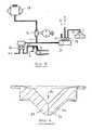
- Fig. 3 is a schematic view of a lubricating system including the pump 16 illustrated in Figs. 1 and 2.
- the pump 16 is connected to tubular means 17 which are provided for supplying lubricating fluid from a reservoir 18 to bearings A,B,C (only one shown in the Drawings) and chains D,E,F within a machine (not shown) which requires continuous lubrication.
- Restrictors 21-25 each have an orifice of a predetermined size, or are adjustable so as to provide orifices of required sizes. These restrictors are located in the tubular system and connected to respective lubricating fluid inlets 26 for the bearings of the machine. The sizes of the orifices, i.e.
- the fluid resistance offered by each of the restrictors is selected with regard to the amount of lubricating fluid required by the bearings. Some bearings will be larger than others and/or subject to greater stresses and these bearings will require more lubricating fluid (oil) than others. Also, in view of the very small bore of the piping used in the tubular system 17, bearings which are more remote from the pump 16 may require to be connected to restrictors which offer less resistance than restrictors which are closer to pump 16. Whilst restrictors having orifices of a fixed size can be used, it would also be possible to use adjustable restrictors which can be adjusted so as to provide the required fluid resistance in order to balance or "tune" the lubricating system.
- the lubricating system including the pump 16 is designed to suit a particular machine and its lubricating requirements.
- the pump 16 may deliver 1.0cc of oil each time the cap 9 is moved by the displacement force towards the body 4.
- the cap 9 may be displaced 10 times during the course of a day.
- the rate of displacement can be increased by reducing the stroke length of the cylinder 2 simply by moving the body 4 further away from the displacement force.
- the body 4 may be slidably mounted and clamped in position by suitable means (not shown) to enable the stroke length to be adjusted.
- suitable means not shown
- non-return valve 13 When the system of Fig. 3 is under pressure, non-return valve 13 is open due to the pressure exerted by the displacement of cylinder 2. This pressure continues to rise whilst the cylinder 2 is positively displaced by the driving force. When the driving force is removed, the spring 10 will exert a returning force on the cylinder 2. However, if the pressure within the chamber portion 7 of the pump 16 is still high, this pressure will exceed the return bias of spring 10 as well as maintaining the return valve 13 in its open position. Therefore, the cylinder 2 will not be returned to its starting position by the spring 10. The effect of this is to hold the remote end or cap 9 of cylinder 2 away from the displacement force (e.g. a rotating cam, not shown) and hence the cylinder 2 will not be driven.
- the displacement force e.g. a rotating cam, not shown
- the spring 10 will gradually cause the cylinder to extend more and more from the body 4, whereby the cylinder 2 will be driven over a fraction of its stroke due to the displacement force.
- the pump 16 thereby adapts itself to the required pressure in the lubricating system and this avoids the above mentioned problem of a dangerous increase in back pressure.
- the compression strength of spring 10 and of the means biasing non-return valve 13 are 10 taken into account along with the amount of fluid displaced by the pump.
- the sizes of the restrictors 21-24 and the bore of the tubular system are also factors which require consideration. However, it can be stated that the maximum pressure within chamber 7 just exceeds the pressure exerted by spring 10 in most cases where the preferred embodiment of the invention is used. Generally speaking, calculations are made to determine the required dimensions and final adjustments are made by trial and error.
- Fig. 1 illustrates conventional spring biased ball non-return valves
- the type of non-return valve which comprises two or more cusps which close together and which are forced apart by pressure on the supply side.
- a similar valve is found in the human heart.
- Such valves are herein referred to as cusp valves.
- a suitable cusp valve is shown schematically in Fig. 4. It is made of resilient plastics material and has the shape of a beak with confronting cusps 29,30 divided by a slit 31. Pressure exerted in the direction of the arrow 32 forces the cusps open and they close due to the natural resilience of the material and the shape in which they are moulded.
- the valve is mounted in a suitable supporting structure (not shown for greater clarity) which supplies lubricating fluid to the underside of the valve and which conducts the fluid to the pipe 17.
- Diaphragm valves could also be used to provide the same effect.
Abstract
Description
- This invention relates to a lubricating system which uses a pump of the kind in which a static piston is slidably received within a movable cylinder.
- One object of the invention is to provide a pump of simple construction and which is therefore inexpensive to manufacture and reliable in use. A pump according to the invention may be used, for example, for pumping medium viscosity oil. Such a pump could be used on agricultural machinery, such as a baler, which provides a regular oscillatory displacement force for operating the pump.
- Another object of the invention is to provide a lubricating system having a simple but reliable pump, the system also being self-adaptive in governing its own pressure of lubricating fluid.
- According to one aspect of the invention, a pump comprises a static piston slidably received within a movable cylinder, a first non-return valve which provides an inlet to the cylinder, and biasing means located in the cylinder for returning the cylinder to a starting position, the piston being anchored to a body which slidably supports the cylinder, the cylinder having a portion which projects from the body to enable a displacement force to be applied to the cylinder to obtain a pumping action, characterised in that the cylinder extends longitudinally from each side of the piston so as to define a chamber portion on one side of the piston and the end portion which projects from the body; said first non-return valve and a second non-return valve, which provides an outlet from the cylinder, communicating with said chamber portion, whereby the pressure exerted in said chamber portion, due to said pumping action, urges the cylinder in a direction opposite to the direction in which the biasing means urges the cylinder.
- In a preferred embodiment, the piston is statically anchored to the body by a retaining member, such as a pin, which passes through slots in the cylinder and is fixed to the body.
- Preferably, the biasing means is a spring which is located between the other side of the piston and the remote end of the cylinder.
- According to another aspect of the invention, a lubricating system comprises the above mentioned pump and it further includes tubular means connected to said second non-return valve, which tubular means are provided to supply lubricating fluid to one or more bearings or chains in a machine connected to the system, and restricting means having a predetermined fluidic resistance, which restricting means are provided to restrict the supply of the lubricating fluid to the respective bearings or chains, the arrangement being such that the force exerted by the biasing means on the cylinder is less than a predetermined maximum fluidic pressure in the chamber portion of the cylinder whereby the cylinder is retained in at least a partially displaced position so that its projecting end portion is spaced from the displacement force over part of the normal stroke of the cylinder.
- A preferred embodiment of the invention will now be described with reference to the accompanying Drawings in which:
- Figure 1 is a side elevation, in section, of a pump,
- Figure 2 is an end-on view of the pump shown in Figure 1.
- Figure 3 is a schematic view of a lubricating system according to the invention, and
- Figure 4 schematically illustrates a preferred non-return valve.
- Referring to the Drawings, a pump comprises a
piston 1, which may be made of steel, slidably received in acylinder 2, which may be made of brass. A doubled cup seal 3 mounted on thepiston 1 seals the piston to the cylinder whilst enabling the cylinder to move relative thereto. The piston is anchored to a body 4 by means of a retaining roll pin 5. The body 4 is preferably made of Nylon 66 since this enables thecylinder 2 to be firmly supported whilst enabling relatively free slidable movement.Slots 6 in the side ofcylinder 2 accommodate pin 5 during reciprocal movement. Since the seal 3 seals the chamber portion 7, theslots 6 do not leak. - An
end portion 8 ofcylinder 2 projects outwardly from the body 4 and terminates in a screw cap 9. Areturn spring 10 is located within thecylinder 2, i.e. between one end of thepiston 1 and the inner end wall of the cap 9. - A chamber portion 7 of
cylinder 2 projects from the body 4 and has a screw thread on which is mounted anon-return valve assembly 11.Assembly 11 is therefore supported by thecylinder 2 and moves bodily with it.Assembly 11 contains spring-loadednon-return ball valves outlet port 14 and aninlet port 15. Thus, ascylinder 2 moves relative to piston 1 a charge of material is sucked into portion 7 from theinlet 15 and is discharged through theoutlet 14. - A reciprocating displacement force is applied to the
end cap 8 in order to displacecylinder 2 regularly to the lefthand side of the Drawing.Spring 10 is provided for returningcylinder 2 to its starting position after the displacement force has been removed. This return of the cylinder is delayed as explained below. - The preferred embodiment of the invention provides a simple single piston pump suitable for pumping medium viscosity oil. It governs its own pressure, e.g. to a maximum of 120 psi. The quantity of oil transported depends on the length of stroke, e.g. up to a maximum of 1.5 cc. The pump is designed with a minimum of parts to provide low cost manufacture and reliability of operation. This is due, in particular, to the use of a static piston anchored within a body in which the cylinder is free to move. Stroke adjustments can easily be made by positioning the body 4 either further or nearer to the means for providing a displacement force on cap 9.
- Fig. 3 is a schematic view of a lubricating system including the
pump 16 illustrated in Figs. 1 and 2. Thepump 16 is connected totubular means 17 which are provided for supplying lubricating fluid from areservoir 18 to bearings A,B,C (only one shown in the Drawings) and chains D,E,F within a machine (not shown) which requires continuous lubrication. Restrictors 21-25 each have an orifice of a predetermined size, or are adjustable so as to provide orifices of required sizes. These restrictors are located in the tubular system and connected to respective lubricatingfluid inlets 26 for the bearings of the machine. The sizes of the orifices, i.e. the fluid resistance offered by each of the restrictors is selected with regard to the amount of lubricating fluid required by the bearings. Some bearings will be larger than others and/or subject to greater stresses and these bearings will require more lubricating fluid (oil) than others. Also, in view of the very small bore of the piping used in thetubular system 17, bearings which are more remote from thepump 16 may require to be connected to restrictors which offer less resistance than restrictors which are closer topump 16. Whilst restrictors having orifices of a fixed size can be used, it would also be possible to use adjustable restrictors which can be adjusted so as to provide the required fluid resistance in order to balance or "tune" the lubricating system. - The lubricating system, including the
pump 16 is designed to suit a particular machine and its lubricating requirements. For example, thepump 16 may deliver 1.0cc of oil each time the cap 9 is moved by the displacement force towards the body 4. Assuming that the total lubricating requirements of machine 20 are 10cc per 24 hours, the cap 9 may be displaced 10 times during the course of a day. The rate of displacement can be increased by reducing the stroke length of thecylinder 2 simply by moving the body 4 further away from the displacement force. The body 4 may be slidably mounted and clamped in position by suitable means (not shown) to enable the stroke length to be adjusted. Thus, if the stroke lengths were adjusted so that the pump delivered 0.5cc for each displacement of cap 9, the displacement rate would be 20 strokes per day. - Whilst this delivery rate is desirable, there will be a build-up in the pressure of the lubricating fluid in the
tubular system 17 after the system has been fully primed and is operating normally. This is due to the fact that the restrictors 21-24 and the clearance between the surfaces of the bearings A-D offer such a fluidic resistance that only minute quantities of oil can escape onto the bearings whilst pressure is exerted on the supply side of thepump 16 andnon-return valve 13. This would normally cause a high back pressure to build up if a pump were used which was subject to direct displacement in both directions of reciprocal movement. This would be the case, for example, with a pump in which a piston was forced in one direction and then forced in the opposite direction. This is similar to an automotive engine where the piston is connected, by a crank rod, to a rotating crank. If such a piston and cylinder arrangement were used in the lubricating system of Fig. 3, there is a danger that a rupture would occur due to the high back pressure, i.e. where the oil could not escape from the bearings fast enough. However, this situation could not arise with the pump and lubricating system of the invention because it is self-adaptive in governing its own pressure of lubricating fluid. This will be explained in more detail below. - When the system of Fig. 3 is under pressure,
non-return valve 13 is open due to the pressure exerted by the displacement ofcylinder 2. This pressure continues to rise whilst thecylinder 2 is positively displaced by the driving force. When the driving force is removed, thespring 10 will exert a returning force on thecylinder 2. However, if the pressure within the chamber portion 7 of thepump 16 is still high, this pressure will exceed the return bias ofspring 10 as well as maintaining thereturn valve 13 in its open position. Therefore, thecylinder 2 will not be returned to its starting position by thespring 10. The effect of this is to hold the remote end or cap 9 ofcylinder 2 away from the displacement force (e.g. a rotating cam, not shown) and hence thecylinder 2 will not be driven. However, as the pressure within the chamber 7 decreases, due to the escape of oil at the bearings A-D, thespring 10 will gradually cause the cylinder to extend more and more from the body 4, whereby thecylinder 2 will be driven over a fraction of its stroke due to the displacement force. Thepump 16 thereby adapts itself to the required pressure in the lubricating system and this avoids the above mentioned problem of a dangerous increase in back pressure. - In designing the system, the compression strength of
spring 10 and of the means biasingnon-return valve 13 are 10 taken into account along with the amount of fluid displaced by the pump. The sizes of the restrictors 21-24 and the bore of the tubular system are also factors which require consideration. However, it can be stated that the maximum pressure within chamber 7 just exceeds the pressure exerted byspring 10 in most cases where the preferred embodiment of the invention is used. Generally speaking, calculations are made to determine the required dimensions and final adjustments are made by trial and error. - Whilst Fig. 1 illustrates conventional spring biased ball non-return valves, it is preferred to use the type of non-return valve which comprises two or more cusps which close together and which are forced apart by pressure on the supply side. A similar valve is found in the human heart. Such valves are herein referred to as cusp valves. A suitable cusp valve is shown schematically in Fig. 4. It is made of resilient plastics material and has the shape of a beak with confronting
cusps slit 31. Pressure exerted in the direction of thearrow 32 forces the cusps open and they close due to the natural resilience of the material and the shape in which they are moulded. The valve is mounted in a suitable supporting structure (not shown for greater clarity) which supplies lubricating fluid to the underside of the valve and which conducts the fluid to thepipe 17. - Diaphragm valves could also be used to provide the same effect.
- Whilst an embodiment of the invention has been described by way of an example, modifications and changes are possible with the scope of the invention.
Claims (7)
Applications Claiming Priority (2)
| Application Number | Priority Date | Filing Date | Title |
|---|---|---|---|
| GB8922476A GB2236559A (en) | 1989-10-05 | 1989-10-05 | Pump |
| GB8922476 | 1989-10-05 |
Publications (2)
| Publication Number | Publication Date |
|---|---|
| EP0421807A1 true EP0421807A1 (en) | 1991-04-10 |
| EP0421807B1 EP0421807B1 (en) | 1994-09-14 |
Family
ID=10664117
Family Applications (1)
| Application Number | Title | Priority Date | Filing Date |
|---|---|---|---|
| EP90310932A Expired - Lifetime EP0421807B1 (en) | 1989-10-05 | 1990-10-05 | Lubricating system and pump |
Country Status (5)
| Country | Link |
|---|---|
| US (1) | US5080196A (en) |
| EP (1) | EP0421807B1 (en) |
| AU (1) | AU6386290A (en) |
| DE (1) | DE69012496T2 (en) |
| GB (1) | GB2236559A (en) |
Cited By (1)
| Publication number | Priority date | Publication date | Assignee | Title |
|---|---|---|---|---|
| DE4339178A1 (en) * | 1992-11-16 | 1994-05-19 | Unisia Jecs Corp | Pump for liquid hydrogen - Has reciprocating cylinder driven by crank with internal piston supported by frame on universal joint |
Families Citing this family (1)
| Publication number | Priority date | Publication date | Assignee | Title |
|---|---|---|---|---|
| TW201024526A (en) * | 2008-12-23 | 2010-07-01 | Cheng-Chin Kung | Cooling and circulating system for engine oil |
Citations (5)
| Publication number | Priority date | Publication date | Assignee | Title |
|---|---|---|---|---|
| US2092920A (en) * | 1936-02-06 | 1937-09-14 | Orlando B Johnson | Air pump |
| US2213946A (en) * | 1937-09-20 | 1940-09-10 | Hydraulic Brake Co | Fluid pressure producing device |
| FR991896A (en) * | 1949-05-23 | 1951-10-11 | Usines De Construction D App F | Advanced hermetic compressor |
| FR1008027A (en) * | 1950-01-06 | 1952-05-13 | Multi-effect reciprocating rectilinear motion suction pump device | |
| EP0264632A2 (en) * | 1986-10-13 | 1988-04-27 | Afros S.P.A. | Coaxial - piston pumping unit |
Family Cites Families (6)
| Publication number | Priority date | Publication date | Assignee | Title |
|---|---|---|---|---|
| GB407075A (en) * | 1932-09-08 | 1934-03-08 | William Mair Rolph | Improvements in pump or syringe apparatus for delivering liquid |
| US2028098A (en) * | 1934-05-09 | 1936-01-14 | John Dobranc | Beverage dispensing device |
| US2294673A (en) * | 1939-02-15 | 1942-09-01 | Prete James V Lo | Automatic lubricator |
| US2686476A (en) * | 1951-08-04 | 1954-08-17 | Lincoln Eng Co | Injector |
| US3635597A (en) * | 1969-09-04 | 1972-01-18 | W C Bonner Co Inc | Injection pump |
| NL7811280A (en) * | 1978-11-15 | 1980-05-19 | Hoogovens Ijmuiden Bv | RAIL SYSTEM EQUIPPED WITH A HYDRAULIC CYLINDER NEXT TO A RAIL, AND THIS HYDRAULIC CYLINDER. |
-
1989
- 1989-10-05 GB GB8922476A patent/GB2236559A/en not_active Withdrawn
-
1990
- 1990-10-04 US US07/592,920 patent/US5080196A/en not_active Expired - Fee Related
- 1990-10-05 AU AU63862/90A patent/AU6386290A/en not_active Abandoned
- 1990-10-05 DE DE69012496T patent/DE69012496T2/en not_active Expired - Fee Related
- 1990-10-05 EP EP90310932A patent/EP0421807B1/en not_active Expired - Lifetime
Patent Citations (5)
| Publication number | Priority date | Publication date | Assignee | Title |
|---|---|---|---|---|
| US2092920A (en) * | 1936-02-06 | 1937-09-14 | Orlando B Johnson | Air pump |
| US2213946A (en) * | 1937-09-20 | 1940-09-10 | Hydraulic Brake Co | Fluid pressure producing device |
| FR991896A (en) * | 1949-05-23 | 1951-10-11 | Usines De Construction D App F | Advanced hermetic compressor |
| FR1008027A (en) * | 1950-01-06 | 1952-05-13 | Multi-effect reciprocating rectilinear motion suction pump device | |
| EP0264632A2 (en) * | 1986-10-13 | 1988-04-27 | Afros S.P.A. | Coaxial - piston pumping unit |
Cited By (1)
| Publication number | Priority date | Publication date | Assignee | Title |
|---|---|---|---|---|
| DE4339178A1 (en) * | 1992-11-16 | 1994-05-19 | Unisia Jecs Corp | Pump for liquid hydrogen - Has reciprocating cylinder driven by crank with internal piston supported by frame on universal joint |
Also Published As
| Publication number | Publication date |
|---|---|
| DE69012496D1 (en) | 1994-10-20 |
| DE69012496T2 (en) | 1995-02-23 |
| US5080196A (en) | 1992-01-14 |
| GB8922476D0 (en) | 1989-11-22 |
| GB2236559A (en) | 1991-04-10 |
| EP0421807B1 (en) | 1994-09-14 |
| AU6386290A (en) | 1991-04-11 |
Similar Documents
| Publication | Publication Date | Title |
|---|---|---|
| CA2233938C (en) | Diaphragm pump with chip resistant valve seats and low velocity check valves | |
| US4068982A (en) | Charge control valve and piston assembly for diaphragm pump | |
| RU2401390C2 (en) | Diaphragm pump and method to control fluid pressure therein | |
| US7108491B2 (en) | High pressure pump | |
| US3957399A (en) | Diaphragm pump | |
| US5876189A (en) | Pumped fluid metering device for the precise feeding of a fluid | |
| US3884598A (en) | Piston assembly for diaphragm pump | |
| JP3990732B2 (en) | High pressure pump that can be used for any fluid | |
| US3912045A (en) | Lubricating pump | |
| CA1254443A (en) | Reciprocating pump | |
| US6071089A (en) | Hydraulic diaphragm pump | |
| GB1518776A (en) | Diaphragm pum | |
| EP1407177B1 (en) | Reciprocating piston pump adjustable inlet ball travel | |
| US4982706A (en) | Valve control apparatus having a magnet valve for internal combustion engines | |
| EP0972936A3 (en) | Positive displacement pumps | |
| CA1122479A (en) | Double-acting differential piston supply pump | |
| EP0421807B1 (en) | Lubricating system and pump | |
| EP1536137A1 (en) | Fuel pump for an internal combustion engine | |
| US4353684A (en) | Pressure limiting device | |
| US20040211628A1 (en) | Quantitative distributor | |
| US5195876A (en) | Plunger pump | |
| KR100388508B1 (en) | Device for lubricating a coupling between two mutually movable parts, particularly a connecting rod/piston coupling | |
| US4934906A (en) | High pressure diaphragm pump | |
| US5624246A (en) | Hydraulic ammonia solution pump | |
| US3578879A (en) | Spring actuated fuel pump for fuel injection systems |
Legal Events
| Date | Code | Title | Description |
|---|---|---|---|
| PUAI | Public reference made under article 153(3) epc to a published international application that has entered the european phase |
Free format text: ORIGINAL CODE: 0009012 |
|
| AK | Designated contracting states |
Kind code of ref document: A1 Designated state(s): BE DE ES FR GB IT NL |
|
| 17P | Request for examination filed |
Effective date: 19910916 |
|
| 17Q | First examination report despatched |
Effective date: 19930223 |
|
| GRAA | (expected) grant |
Free format text: ORIGINAL CODE: 0009210 |
|
| AK | Designated contracting states |
Kind code of ref document: B1 Designated state(s): BE DE ES FR GB IT NL |
|
| PG25 | Lapsed in a contracting state [announced via postgrant information from national office to epo] |
Ref country code: NL Effective date: 19940914 Ref country code: ES Free format text: THE PATENT HAS BEEN ANNULLED BY A DECISION OF A NATIONAL AUTHORITY Effective date: 19940914 Ref country code: BE Effective date: 19940914 |
|
| PGFP | Annual fee paid to national office [announced via postgrant information from national office to epo] |
Ref country code: DE Payment date: 19941010 Year of fee payment: 5 |
|
| REF | Corresponds to: |
Ref document number: 69012496 Country of ref document: DE Date of ref document: 19941020 |
|
| ET | Fr: translation filed | ||
| ITF | It: translation for a ep patent filed |
Owner name: MODIANO & ASSOCIATI S.R.L. |
|
| NLV1 | Nl: lapsed or annulled due to failure to fulfill the requirements of art. 29p and 29m of the patents act | ||
| PLBE | No opposition filed within time limit |
Free format text: ORIGINAL CODE: 0009261 |
|
| STAA | Information on the status of an ep patent application or granted ep patent |
Free format text: STATUS: NO OPPOSITION FILED WITHIN TIME LIMIT |
|
| 26N | No opposition filed | ||
| PG25 | Lapsed in a contracting state [announced via postgrant information from national office to epo] |
Ref country code: DE Effective date: 19960702 |
|
| PGFP | Annual fee paid to national office [announced via postgrant information from national office to epo] |
Ref country code: GB Payment date: 19981009 Year of fee payment: 9 Ref country code: FR Payment date: 19981009 Year of fee payment: 9 |
|
| PG25 | Lapsed in a contracting state [announced via postgrant information from national office to epo] |
Ref country code: GB Free format text: LAPSE BECAUSE OF NON-PAYMENT OF DUE FEES Effective date: 19991005 |
|
| GBPC | Gb: european patent ceased through non-payment of renewal fee |
Effective date: 19991005 |
|
| PG25 | Lapsed in a contracting state [announced via postgrant information from national office to epo] |
Ref country code: FR Free format text: LAPSE BECAUSE OF NON-PAYMENT OF DUE FEES Effective date: 20000630 |
|
| REG | Reference to a national code |
Ref country code: FR Ref legal event code: ST |
|
| PG25 | Lapsed in a contracting state [announced via postgrant information from national office to epo] |
Ref country code: IT Free format text: LAPSE BECAUSE OF NON-PAYMENT OF DUE FEES;WARNING: LAPSES OF ITALIAN PATENTS WITH EFFECTIVE DATE BEFORE 2007 MAY HAVE OCCURRED AT ANY TIME BEFORE 2007. THE CORRECT EFFECTIVE DATE MAY BE DIFFERENT FROM THE ONE RECORDED. Effective date: 20051005 |