EP0421663B1 - Separating and feeding garment parts - Google Patents
Separating and feeding garment parts Download PDFInfo
- Publication number
- EP0421663B1 EP0421663B1 EP90310526A EP90310526A EP0421663B1 EP 0421663 B1 EP0421663 B1 EP 0421663B1 EP 90310526 A EP90310526 A EP 90310526A EP 90310526 A EP90310526 A EP 90310526A EP 0421663 B1 EP0421663 B1 EP 0421663B1
- Authority
- EP
- European Patent Office
- Prior art keywords
- stack
- leading edge
- hold down
- parts
- top part
- Prior art date
- Legal status (The legal status is an assumption and is not a legal conclusion. Google has not performed a legal analysis and makes no representation as to the accuracy of the status listed.)
- Expired - Lifetime
Links
- 238000000926 separation method Methods 0.000 claims abstract description 26
- 230000003287 optical effect Effects 0.000 claims abstract description 11
- 239000000463 material Substances 0.000 claims description 9
- 230000007246 mechanism Effects 0.000 abstract description 10
- 239000004744 fabric Substances 0.000 description 11
- 238000004519 manufacturing process Methods 0.000 description 8
- 239000002184 metal Substances 0.000 description 7
- 238000000034 method Methods 0.000 description 5
- 230000001133 acceleration Effects 0.000 description 3
- 230000000149 penetrating effect Effects 0.000 description 3
- 230000008569 process Effects 0.000 description 3
- 230000003213 activating effect Effects 0.000 description 2
- 238000009958 sewing Methods 0.000 description 2
- 230000009471 action Effects 0.000 description 1
- 238000013459 approach Methods 0.000 description 1
- 230000005540 biological transmission Effects 0.000 description 1
- 230000008859 change Effects 0.000 description 1
- 238000010276 construction Methods 0.000 description 1
- 230000001419 dependent effect Effects 0.000 description 1
- 230000000694 effects Effects 0.000 description 1
- 238000009957 hemming Methods 0.000 description 1
- 239000000203 mixture Substances 0.000 description 1
- 239000007787 solid Substances 0.000 description 1
- 238000011144 upstream manufacturing Methods 0.000 description 1
Images


Classifications
-
- A—HUMAN NECESSITIES
- A41—WEARING APPAREL
- A41H—APPLIANCES OR METHODS FOR MAKING CLOTHES, e.g. FOR DRESS-MAKING OR FOR TAILORING, NOT OTHERWISE PROVIDED FOR
- A41H43/00—Other methods, machines or appliances
- A41H43/02—Handling garment parts or blanks, e.g. feeding, piling, separating or reversing
- A41H43/0228—Separating from piles
-
- B—PERFORMING OPERATIONS; TRANSPORTING
- B65—CONVEYING; PACKING; STORING; HANDLING THIN OR FILAMENTARY MATERIAL
- B65H—HANDLING THIN OR FILAMENTARY MATERIAL, e.g. SHEETS, WEBS, CABLES
- B65H3/00—Separating articles from piles
- B65H3/22—Separating articles from piles by needles or the like engaging the articles
-
- B—PERFORMING OPERATIONS; TRANSPORTING
- B65—CONVEYING; PACKING; STORING; HANDLING THIN OR FILAMENTARY MATERIAL
- B65H—HANDLING THIN OR FILAMENTARY MATERIAL, e.g. SHEETS, WEBS, CABLES
- B65H3/00—Separating articles from piles
- B65H3/46—Supplementary devices or measures to assist separation or prevent double feed
- B65H3/54—Pressing or holding devices
Definitions
- This invention relates to apparatus for the seriatim removal of parts of garment material from a shingled stack of the parts to a predetermined destination, said shingled stack having a top part, a second part, and remaining parts beneath the top part, each part in the stack having a leading edge, a trailing edge, a top surface, and a bottom surface and arranged in a shingled fashion in the stack such that the leading edge of each part in the stack extends beyond the leading edge of any underlying part in the stack, said apparatus comprising: a support surface for supporting at least the top part and some of the remaining parts in the stack as the stack is advanced toward a predetermined location for separation; an engagement means suspended above the support surface and operable for engaging the leading edge of the top part, moving the top part from the stack to the predetermined destination, disengaging itself from the leading edge of the top part, and returning to the predetermined location for removing the next top part in the stack; a hold down means suspended above the support surface, for engaging a part during separation of the top part from the remaining
- the field to which the invention pertains comprises the art of separating and feeding individual garment parts from a stack for supplying the separated parts to a work station at which manufacturing operations are to be conducted on the part.
- Staggering of the edges of parts of a stack which are aligned with each other at the time the parts are cut out may be obtained by various methods. It can for example be obtained by clamping one edge of the stack and rotating the other edge, then clamping the stack adjacent the other edge and releasing the stack at the first point of clamping to permit the stack to remain in the staggered or shingled configuration.
- Certain manufacturing processes in the fabrication of apparel parts also inherently discharge the parts from a work station into a staggered or shingled stack configuration. In some instances, where for example the topside and underside of the apparel part have different surface textures and different friction coefficients with materials such as corduroy or brushed denim, the parts may be shingled and removed from the stack in pairs instead of individually.
- US patent 4688781 discloses separation of parts from the top of a shingled stack in which "following" of the second and subsequent parts was avoided by applying vacuum to the bottom of the leading edge of the second and subsequent parts.
- this solution occasionally produced another problem, depending on the material being separated, in which the trailing edge of the second part would cling and curl over as the top most part was removed.
- US patent 4871161 discloses an improved mechanism which prevented this "curl over” problem by exerting pressure against the trailing edge of the top most part and the remaining parts in the stack, and accelerating the top most part on removal, relying on the "table cloth effect” to retain the second and remaining parts while removing the topmost part from the stack.
- EP-A-0 262 578 (which corresponds to US-A-4 871 161) describes this improved mechanism in the context of apparatus of the kind defined hereinbefore at the beginning.
- the engagement means comprises a picker assembly for grasping and separating the uppermost garment part on the stack with a picker head.
- the hold down means is fixed to a table that provides the support surface.
- Two elongate, vertically disposed pneumatic plunger cylinders in the hold down means are so arranged that their respective plunger rods, each with a resilient friction textured finger cap at the lower end, can be driven down to exert a positive clamping force on the tail end of the first, i.e. topmost, garment part in the stack when the stack is at the station for separation.
- DE-A-20 26 573 (corresponding to US-A-3 588 092) describes a method and apparatus for removing a single ply of fabric from the top of a vertical stack of such plies.
- a pair of rotary torque clamps are lowered onto the top ply at positions upstream from the leading edge of the ply and slightly inward from its side edges.
- Each torque clamp is then turned through an angle so as to cause the leading edge of the top ply to lift up to a vertical condition. This allows a pair of edge clamps to be lowered to clamp the leading edge corners of the remainder of the stack against the supporting surface.
- a gripper head is then moved in to position its lower members on top of the leading edge of the clamped second ply, the torque clamps having been disengaged from the top ply.
- the upper members of the gripper head are operated to clamp the leading edge of the top ply between the upper and lower members of the gripper head, which is then retracted, drawing with it the top ply, which can be released at a position spaced from the stack.
- the present invention provides further improvements in separating and feeding parts of relatively flexible garment materials such as fabric parts of various articles of apparel from a shingled stack of such parts, even though the parts may be formed of various types of fabric having a tendency to cling or resist separation from adjacent parts in the stack, without the need for rapid acceleration of the picker assembly or the use of vacuum for holding down the remaining parts in the stack.
- apparatus of the kind defined hereinbefore at the beginning is characterised in that the hold down means is movable for engaging the trailing edge of the second part during separation of the top part, and in that a locator means is provided for determining the approximate location of the trailing edge of the second part; and a mover means for moving the hold down means as necessary for engaging said trailing edge of said second part; said mover means being responsive to said locator means.
- an improved apparatus particularly adapted for separating and transferring individual apparel parts arranged in a staggered or so-called shingled stack of parts.
- the parts are stacked such that an edge of the top most part, which may be hemmed or unhemmed, or a portion of a surface of the top most part is engaged by any type of picker assembly connected to a transfer mechanism.
- a hold down mechanism applies a perpendicular clamping force on the trailing edge of the second part of the stack and the remaining parts in the stack.
- the hold down mechanism can include rod-like “fingers” which apply a perpendicular frictional force against the top portion of the trailing edge of the second part, or can include needles or other features for penetrating and positively securing the second and remaining parts to prevent "following".
- the hold down mechanism By constructing the hold down mechanism so that the hold down rods or “fingers” can be moved in a controlled fashion in either direction along the axis of travel of the shingled stack of parts, and by using optical and proximity sensors to determine the presence or absence of a part engaged by the picker assembly and whether a single part or more than one party was engaged, the position of the fingers can be automatically adjusted to provide a hold down point on the trailing edge of the second part in the stack to permit the separation of the first part in the stack.
- the apparatus of the present invention is particularly adapted for use in conjunction with the automated manufacture of garment articles of apparel such as denim jeans, and for handling certain parts of the garments in the various stages of the manufacturing process.
- the embodiments of the apparatus described in detail herein are suitable for separating precut parts of fabric for pocket parts of trousers, which parts may be hemmed along the top edge of the pocket part and stacked in a staggered or shingled configuration.
- the parts are oriented relative to each other in the same direction and the corresponding edges are staggered so that an edge or hem of each part is presented to the apparatus for separation of the top part of a stack from the remaining parts in the stack.
- the apparatus may be used in conjunction with separating and feeding various other stacks of different sizes and configurations composed of other garment materials and which may include subassemblies thereof. Parts need not necessarily be hemmed although parts having a hemmed edge or other surface which may be positioned interlocked or engaged will handle with particular ease.
- the separation and feed mechanism is supported on a horizontal surface such as table 10 having vertically adjustable legs 12.
- Feeding conveyor 14 is provided for supporting and advancing a shingled stack as it passes from a source of parts under holddown assembly 16 to ramp 18 where picker assembly 20 can be used to sequentially separate and move each part from the stack to a rear location, for example to transfer conveyor 22.
- Ramp 18 defines an angled surface with respect to the plane of table 10. The ramp 18 merges with a substantially horizontal surface which is traversed by picker assembly 20. These surfaces are polished and smooth to enable low friction movement of the garment parts thereover.
- the angle of conveyor 14 is preferably adjustable to match that of the shingled stack and can be conveniently changed to accommodate different material compositions or other requirements as may become desirable. Further, and also as disclosed in detail in U.S. Patent 4 871 161 the conveyor can be used in conjunction with one or more conveyors operating at relatively different transport speeds to change the spacing of the parts in the shingled stack to aid in separation efficiency.
- Thickness switch 27 is a spring biased metal finger 27a extending over a proximity switch 27b mounted in the support surface in the path of travel of the separated parts during the operation of the picker assembly 20.
- the distance between the metal finger 27a and the proximity switch 27b of thickness detector 27 is set to be slightly greater than the thickness of one part. That is, when one part passes between the metal finger 27a and the proximity switch 27b, the proximity switch 27b continues to sense the presence of the metal finger 27a.
- the metal finger 27a and the proximity switch 27b when two parts pass between the metal finger 27a and the proximity switch 27b, the metal finger 27a is lifted out of range of the proximity switch 27b and a signal is sent to the microprocessor.
- the separated part is pulled under thickness switch 27 by the picker assembly 20. If only one part has been engaged by the picker assembly 20, that part will pass between thickness switch 27 and the support surface without activating the proximity switch 27b. If two parts pass between the thickness switch 27 and the support surface, the proximity switch 27b is activated. If separation by pairs is not desirable, action can then be taken downstream to remove one of the two parts.
- the preferred hold down apparatus 16 comprises a frame 32 having motor mounting bracket 34 and mounting brackets 36, 36' for mounting hold down apparatus 16 in position above conveyor 14.
- a primary feature of hold down apparatus 16 are the hold down fingers 38, 38' and 38''.
- Hold down fingers 38, 38', 38'' are operable between a first "up" position as shown in solid lines in figure 2 where tip 40 is suspended well above conveyor 14 to allow for unimpeded passage of a shingled stack and a second "down" position as shown in phantom lines in figure 2 where tip 40 is adjacent to conveyor 14.
- Hold down fingers 38, 38' and 38'' are preferably constructed from pneumatic cylinders having pneumatic pistons which move out of the cylinders with an increase in air pressure in the "down" position and which move into the cylinder with a decrease in air pressure in the "up” position.
- the pneumatic pistons should be adapted to accept tips 40.
- Tip 40 is preferably a non-penetrating frictional pin-type tip as shown in Figure 1A and 2A. However, one or more of the tips 40 can be a roller-type tip as shown in Figure 2B or a penetrating needle-type tip as shown in Figure 2C.
- the two outside hold down fingers 38, 38'' can be connected through connectors 58, 58'' to the same pneumatic line using a "T" connector (not shown). However, if this is done, the air line attaching finger 38 to the "T" connector should preferably be the same size as the air line attaching finger 38'' to the "T" connector in order to equalize pressure to the two fingers 38, 38''.
- Middle hold down finger 38' is preferably attached to a separate pneumatic line. Control of the air pressure to the hold down fingers 38, 38', 38'' can be effected through means well known in the art such as the use of conventional solenoid switch 60.
- Hold down fingers 38, 38', 38'' are attached to carriage plate 46.
- fingers 38, 38'' are preferably attached in a fixed position, while finger 38' is movably attached to slot 48 which permits the position of finger 38' to be adjusted along the axis of travel of conveyor 14 within the confines of slot 48.
- carriage plate 46 Preferably mounted to the bottom of carriage plate 46 are four wheels 50, 50', 50'', 50''' adapted to travel along rails 52, 52'.
- Rail 52 is mounted on one side of frame 32 parallel to the axis of travel of conveyor 14, and rail 52' is mounted on the opposite side of frame 32, parallel both to the axis of travel of conveyor 14 and to the longitudinal axis of rail 52.
- the position of carriage plate 46 in frame 32 can be adjusted along rails 52, 52' towards or away from picker assembly 20 in order to adjust the position of the hold down tips 40 on the shingled stack in the "down" position to insure that the tips 40 will contact only a trailing edge of the second part in the stack. While such adjustment of the position of carriage plate 46 could be achieved manually, for example by an equipment operator, most preferably the adjustment is done automatically.
- Automatic adjustment of carriage plate 46 is preferably achieved using a stepper motor 30.
- Motor 30 is attached to motor mounting bracket 34.
- Motor 30 drives a belt which in turn drives (rotates) shaft 56 about a longitudinal axis which is parallel to the direction of travel of conveyor 14.
- Shaft 56 is linked to carriage plate 46 for automatically driving carriage plate 46 along rails 52, 52' towards or away from picker assembly 20 when an appropriate signal is received from a microprocessor (not shown).
- Such movement is preferably done in small increments, most preferably increments of about 1/32 or 1/16 inch, until an optimal position of the tips 40, 40', 40'' of fingers 38, 38', 38'' on the trailing edge of the second part in the stack is attained.
- hold down assembly 16 also preferably includes light sensors 24, 24' for setting the initial position of the hold down assembly 16 with respect to the leading edge of the first part in the shingled stack.
- Light sensors 24, 24' detect the presence or absence of the leading edge of the first part in the stack by the presence or absence (interruption) of light from light source 26, which is preferably located on ramp 18.
- the signals from light sensors 24, 24' are transmitted to a microprocessor (not shown) which controls the movement of conveyor 14.
- a microprocessor not shown
- light sensors 24, 24' sense the light from light source 26 and the microprocessor signals the conveyor 14 to advance the stack until a leading edge again interrupts the light from light source 26.
- the operation of the preferred embodiment as shown in the figures is as follows.
- information concerning the size and type of parts and the location of the stack is provided to the microprocessor.
- This information can be provided to the microprocessor, for example, by having an equipment operator key in the information using a keyboard or by tagging each shingled stack with a UPC-type bar coded sticker or card and having an equipment operator scan the sticker or card using a light pen or other conventional bar code scanning apparatus to transmit the information to the microprocessor.
- stepper motor 30 moves carriage plate 46 to an initial position based upon the information concerning the size and type of parts in the stack.
- conveyor 14 stops.
- the incremental movement of conveyor 14 is described in more detail in U.S. patent 4871161.
- Hold down fingers 38, 38', 38'' are placed in the down position e.g., by supplying air through connectors 58, 58', 58'' to pneumatic fingers 38, 38', 38''.
- Control of the air pressure is effected through one or more solenoids 60, whereby the pneumatic pistons of hold down fingers 38, 38', 38'' are stroked downwardly from the position shown solid to the position shown in phantom in Fig. 2.
- picker assembly 20 moves to a first position where it engages the first (top most) part in the shingled stack and moves to a second position rearward where it disengages, for example, at transfer conveyor 22. If all goes well, and carriage plate 46 was properly positioned initially, as picker assembly 20 moves toward the second position, the first part will be pulled under thickness switch 27 and the attached proximity switch will not be activated, and after the first part disengages from picker assembly 20 at the second position, the transmission of light from source 29 to optical detector 28 will be interrupted by the passage of the first part over light source 29 to its rearward destination, indicating the successful removal of the first part.
- the microprocessor Upon receiving a signal from optical detectors 24, 24' indicating the absence of a leading edge, the microprocessor will activate the solenoid switch or switches 60 to move hold down fingers 38, 38', 38'' to the "up" position, and activate the conveyor 14 to advance the stack until the next leading edge is sensed, at which time the conveyor 14 will stop and the process will be repeated.
- the hold down fingers 38, 38' 38'' will be either too far forward or too far back from the optimum hold down position. If the hold down fingers 38, 38', 38'' are too far forward, they will hold down the trailing edge of the first part in the stack. When this condition exists, the optical sensor 28 will not detect the passage of a part after the picker assembly has reached the second position.
- the microcomputer will interpret the failure to detect the passage of the separated part as meaning the carriage plate 46 is too far forward resulting in the trailing edge of the first part being held down, since if the trailing edge of the first part is engaged by hold down fingers 38, 38', 38'' the picker assembly 20 will not be able to separate the first part from the top of the shingled stack.
- the microcomputer will then signal the stepper motor 30 to move the carriage plate 46 away from the picker assembly 20 by one increment, and the picker assembly 20 will be activated again. This process will be repeated until the optical detector 28 senses the passage of a separated part (the interruption of light from source 29) following the disengagement of the picker assembly 20 at the second position.
- the conveyor 14 will not be activated to advance the shingled stack until the leading edge of the first part is successfully removed. At that time, light sensors 24, 24' will sense the light from source 26 and the microprocessor will activate the conveyor 14 to advance the stack until the next leading edge is detected (and light from source 26 is again interrupted).
- the picker assembly 20 will pull two parts between the metal finger 27a and the proximity switch 27b, activating the proximity switch attached to thickness switch 27. This will send a signal to the microprocessor which will be interpreted as meaning that the carriage plate is set too far back, and the microprocessor will signal the stepping motor 30 to move the carriage plate 46 forward one increment towards the picker assembly. Additionally, the microprocessor can signal an auxiliary device (not shown) downstream from the thickness switch 27 for removing one of the two separated parts if the separation of parts in pairs is not desirable. The process is then repeated until one part only is removed.
Landscapes
- Engineering & Computer Science (AREA)
- Mechanical Engineering (AREA)
- Textile Engineering (AREA)
- Sheets, Magazines, And Separation Thereof (AREA)
- Treatment Of Fiber Materials (AREA)
- Preliminary Treatment Of Fibers (AREA)
- Forming Counted Batches (AREA)
- Sewing Machines And Sewing (AREA)
- Pile Receivers (AREA)
- Centrifugal Separators (AREA)
- Details Of Garments (AREA)
- Feeding Of Articles To Conveyors (AREA)
Abstract
Description
- This invention relates to apparatus for the seriatim removal of parts of garment material from a shingled stack of the parts to a predetermined destination, said shingled stack having a top part, a second part, and remaining parts beneath the top part, each part in the stack having a leading edge, a trailing edge, a top surface, and a bottom surface and arranged in a shingled fashion in the stack such that the leading edge of each part in the stack extends beyond the leading edge of any underlying part in the stack, said apparatus comprising:
a support surface for supporting at least the top part and some of the remaining parts in the stack as the stack is advanced toward a predetermined location for separation;
an engagement means suspended above the support surface and operable for engaging the leading edge of the top part, moving the top part from the stack to the predetermined destination, disengaging itself from the leading edge of the top part, and returning to the predetermined location for removing the next top part in the stack;
a hold down means suspended above the support surface, for engaging a part during separation of the top part from the remaining parts of the stack. - The field to which the invention pertains comprises the art of separating and feeding individual garment parts from a stack for supplying the separated parts to a work station at which manufacturing operations are to be conducted on the part.
- In the production of garment goods assembled from fabric or other apparel materials, it is customary to cut a number of parts simultaneously from a stack of plural layers or sheets of fabric followed by separation of the fabric layers for further operations. In the manufacture of goods such as shirts and pants, for example, various parts are subjected to preliminary sewing operations such as hemming and/or partial preassembly and then restacked in one form or another and fed to a further operation. The parts are then normally required to be separated from the stack prior to each successive sewing operation.
- Separation of fabric parts from a stack of parts of like material can be particularly difficult. A major difficulty encountered in separation occurs when the second or subsequent parts in the stack "follow" the top most part as it is being removed. Because fabric is flexible and often has a texture with a relatively high coefficient of friction, like parts tend to cling together causing the "following" phenomenon whereby when a top part is engaged and pulled from a stack, the second and possibly other parts will cling to the engaged part and be dragged off the stack with it. Reliable separation processes are therefore needed to facilitate the automation of the manufacturing process.
- US patents 4871161 and 4688781 describe the separation of fabric parts from a stack of like parts which are somewhat staggered so that corresponding edges of adjacent parts are arranged somewhat like roof shingles, hence the term "shingled stack", by which improved separation techniques are possible.
- Staggering of the edges of parts of a stack which are aligned with each other at the time the parts are cut out may be obtained by various methods. It can for example be obtained by clamping one edge of the stack and rotating the other edge, then clamping the stack adjacent the other edge and releasing the stack at the first point of clamping to permit the stack to remain in the staggered or shingled configuration. Certain manufacturing processes in the fabrication of apparel parts also inherently discharge the parts from a work station into a staggered or shingled stack configuration. In some instances, where for example the topside and underside of the apparel part have different surface textures and different friction coefficients with materials such as corduroy or brushed denim, the parts may be shingled and removed from the stack in pairs instead of individually.
- US patent 4688781 discloses separation of parts from the top of a shingled stack in which "following" of the second and subsequent parts was avoided by applying vacuum to the bottom of the leading edge of the second and subsequent parts. However, this solution occasionally produced another problem, depending on the material being separated, in which the trailing edge of the second part would cling and curl over as the top most part was removed. US patent 4871161 discloses an improved mechanism which prevented this "curl over" problem by exerting pressure against the trailing edge of the top most part and the remaining parts in the stack, and accelerating the top most part on removal, relying on the "table cloth effect" to retain the second and remaining parts while removing the topmost part from the stack.
- EP-A-0 262 578 (which corresponds to US-A-4 871 161) describes this improved mechanism in the context of apparatus of the kind defined hereinbefore at the beginning. The engagement means comprises a picker assembly for grasping and separating the uppermost garment part on the stack with a picker head. The hold down means is fixed to a table that provides the support surface. Two elongate, vertically disposed pneumatic plunger cylinders in the hold down means are so arranged that their respective plunger rods, each with a resilient friction textured finger cap at the lower end, can be driven down to exert a positive clamping force on the tail end of the first, i.e. topmost, garment part in the stack when the stack is at the station for separation. When the stack is at this station, vacuum is applied through apertures in a ramp on which the undersides of the leading edges of at least the first and second garment parts rest. During acceleration of the first part by the picker assembly, the remainder of the stack is held in place by a combination of the clamping force imposed by the hold down means, and vacuum applied to the underside of the stack through the ramp apertures and other apertures.
- While this known mechanism solved the "following" problem, it limited the type of picker assembly which could be used by requiring rapid acceleration of the picker assembly and by using vacuum as a means for holding down the leading edge of the second part in the stack.
- DE-A-20 26 573 (corresponding to US-A-3 588 092) describes a method and apparatus for removing a single ply of fabric from the top of a vertical stack of such plies. At the separation station, a pair of rotary torque clamps are lowered onto the top ply at positions upstream from the leading edge of the ply and slightly inward from its side edges. Each torque clamp is then turned through an angle so as to cause the leading edge of the top ply to lift up to a vertical condition. This allows a pair of edge clamps to be lowered to clamp the leading edge corners of the remainder of the stack against the supporting surface. A gripper head is then moved in to position its lower members on top of the leading edge of the clamped second ply, the torque clamps having been disengaged from the top ply. The upper members of the gripper head are operated to clamp the leading edge of the top ply between the upper and lower members of the gripper head, which is then retracted, drawing with it the top ply, which can be released at a position spaced from the stack.
- The present invention provides further improvements in separating and feeding parts of relatively flexible garment materials such as fabric parts of various articles of apparel from a shingled stack of such parts, even though the parts may be formed of various types of fabric having a tendency to cling or resist separation from adjacent parts in the stack, without the need for rapid acceleration of the picker assembly or the use of vacuum for holding down the remaining parts in the stack.
- According to the present invention, apparatus of the kind defined hereinbefore at the beginning is characterised in that the hold down means is movable for engaging the trailing edge of the second part during separation of the top part, and in that a locator means is provided for determining the approximate location of the trailing edge of the second part; and a mover means for moving the hold down means as necessary for engaging said trailing edge of said second part; said mover means being responsive to said locator means.
- In accordance with one embodiment of the present invention there is provided an improved apparatus particularly adapted for separating and transferring individual apparel parts arranged in a staggered or so-called shingled stack of parts. In this embodiment, the parts are stacked such that an edge of the top most part, which may be hemmed or unhemmed, or a portion of a surface of the top most part is engaged by any type of picker assembly connected to a transfer mechanism. At the same time the picker assembly engages the first (top most) part in the shingled stack, a hold down mechanism applies a perpendicular clamping force on the trailing edge of the second part of the stack and the remaining parts in the stack. The hold down mechanism can include rod-like "fingers" which apply a perpendicular frictional force against the top portion of the trailing edge of the second part, or can include needles or other features for penetrating and positively securing the second and remaining parts to prevent "following".
- By constructing the hold down mechanism so that the hold down rods or "fingers" can be moved in a controlled fashion in either direction along the axis of travel of the shingled stack of parts, and by using optical and proximity sensors to determine the presence or absence of a part engaged by the picker assembly and whether a single part or more than one party was engaged, the position of the fingers can be automatically adjusted to provide a hold down point on the trailing edge of the second part in the stack to permit the separation of the first part in the stack.
- Other embodiments of the invention are set out in dependent claims 2-18
The invention will now be described by way of example with reference to the accompanying drawings, in which: -
- Fig. 1 is a perspective side view of an apparatus of the present invention;
- Fig. 1A is a side view of a shingled stack showing a hold down finger engaging the trailing edge of the second part in the stack in the "down" position;
- Fig. 1B is a side view of an apparatus of the present invention supported on a table;
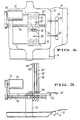
- Fig. 2 is a back view of a hold down apparatus of the present invention;
- Fig. 2A, 2B and 2C illustrate different tips which can be used with a hold down apparatus as shown in Figure 2;
- Figure 3 is a side view of a hold down apparatus of the present invention;
- Figure 4 is a top view of a hold down apparatus of the present invention;
- In the description which follows, like parts are marked throughout the specification and drawings with the same reference numerals, respectively. The drawings are not necessarily to scale and certain features may be shown exaggerated in scale or in somewhat schematic form in the interest of clarity and conciseness.
- The apparatus of the present invention is particularly adapted for use in conjunction with the automated manufacture of garment articles of apparel such as denim jeans, and for handling certain parts of the garments in the various stages of the manufacturing process. In particular, the embodiments of the apparatus described in detail herein are suitable for separating precut parts of fabric for pocket parts of trousers, which parts may be hemmed along the top edge of the pocket part and stacked in a staggered or shingled configuration. In that arrangement, the parts are oriented relative to each other in the same direction and the corresponding edges are staggered so that an edge or hem of each part is presented to the apparatus for separation of the top part of a stack from the remaining parts in the stack. Those skilled in the art will recognize that the apparatus may be used in conjunction with separating and feeding various other stacks of different sizes and configurations composed of other garment materials and which may include subassemblies thereof. Parts need not necessarily be hemmed although parts having a hemmed edge or other surface which may be positioned interlocked or engaged will handle with particular ease.
- Referring initially to Figures 1, 1A and 1B of the drawings, the separation and feed mechanism is supported on a horizontal surface such as table 10 having vertically
adjustable legs 12.Feeding conveyor 14 is provided for supporting and advancing a shingled stack as it passes from a source of parts underholddown assembly 16 toramp 18 wherepicker assembly 20 can be used to sequentially separate and move each part from the stack to a rear location, for example to transferconveyor 22.Ramp 18 defines an angled surface with respect to the plane of table 10. Theramp 18 merges with a substantially horizontal surface which is traversed bypicker assembly 20. These surfaces are polished and smooth to enable low friction movement of the garment parts thereover. - As disclosed in detail in U.S. Patent 4871161 the angle of
conveyor 14 is preferably adjustable to match that of the shingled stack and can be conveniently changed to accommodate different material compositions or other requirements as may become desirable. Further, and also as disclosed in detail in U.S. Patent 4 871 161 the conveyor can be used in conjunction with one or more conveyors operating at relatively different transport speeds to change the spacing of the parts in the shingled stack to aid in separation efficiency. - Optical sensors (photocells) 24, 24', and 28 and
thickness switch 27 are provided to control and adjust the position of hold downassembly 16 as described more fully below.Thickness switch 27 is a spring biasedmetal finger 27a extending over aproximity switch 27b mounted in the support surface in the path of travel of the separated parts during the operation of thepicker assembly 20. The distance between themetal finger 27a and theproximity switch 27b ofthickness detector 27 is set to be slightly greater than the thickness of one part. That is, when one part passes between themetal finger 27a and theproximity switch 27b, theproximity switch 27b continues to sense the presence of themetal finger 27a. However, when two parts pass between themetal finger 27a and theproximity switch 27b, themetal finger 27a is lifted out of range of theproximity switch 27b and a signal is sent to the microprocessor. During operation of thepicker assembly 20, the separated part is pulled underthickness switch 27 by thepicker assembly 20. If only one part has been engaged by thepicker assembly 20, that part will pass betweenthickness switch 27 and the support surface without activating theproximity switch 27b. If two parts pass between thethickness switch 27 and the support surface, theproximity switch 27b is activated. If separation by pairs is not desirable, action can then be taken downstream to remove one of the two parts. - Referring to all the figures, the preferred hold down
apparatus 16 comprises aframe 32 havingmotor mounting bracket 34 and mountingbrackets 36, 36' for mounting hold downapparatus 16 in position aboveconveyor 14. A primary feature of hold downapparatus 16 are the hold downfingers 38, 38' and 38''. - Preferably, there are three hold down
fingers 38, 38', 38'', however, depending upon the size and shape of the parts in the shingled stack, separation may be achieved with fewer or more hold down fingers. Hold downfingers 38, 38' and 38'' are operable between a first "up" position as shown in solid lines in figure 2 wheretip 40 is suspended well aboveconveyor 14 to allow for unimpeded passage of a shingled stack and a second "down" position as shown in phantom lines in figure 2 wheretip 40 is adjacent toconveyor 14. - Hold down
fingers 38, 38' and 38'' are preferably constructed from pneumatic cylinders having pneumatic pistons which move out of the cylinders with an increase in air pressure in the "down" position and which move into the cylinder with a decrease in air pressure in the "up" position. The pneumatic pistons should be adapted to accepttips 40.Tip 40 is preferably a non-penetrating frictional pin-type tip as shown in Figure 1A and 2A. However, one or more of thetips 40 can be a roller-type tip as shown in Figure 2B or a penetrating needle-type tip as shown in Figure 2C. - The two outside hold down
fingers 38, 38'' can be connected throughconnectors 58, 58'' to the same pneumatic line using a "T" connector (not shown). However, if this is done, the airline attaching finger 38 to the "T" connector should preferably be the same size as the air line attaching finger 38'' to the "T" connector in order to equalize pressure to the twofingers 38, 38''. Middle hold down finger 38' is preferably attached to a separate pneumatic line. Control of the air pressure to the hold downfingers 38, 38', 38'' can be effected through means well known in the art such as the use ofconventional solenoid switch 60. - Hold down
fingers 38, 38', 38'' are attached tocarriage plate 46. As shown in Figure 4,fingers 38, 38'' are preferably attached in a fixed position, while finger 38' is movably attached to slot 48 which permits the position of finger 38' to be adjusted along the axis of travel ofconveyor 14 within the confines ofslot 48. This permits the position of hold downfingers 38, 38', 38'' to be adjusted with respect to each other to conform to the shape of the trailing edge of the parts to be separated. It would, of course, be possible to attach all three offingers 38, 38' and 38'' tocarriage plate 46 through slots to permit adjustment. It would also be possible to use slots perpendicular to or at an angle to the longitudinal axis ofconveyor 14 to permit further adjustment of the spacing between the fingers to accomodate many different sizes and shapes of parts in the shingled stack. - Preferably mounted to the bottom of
carriage plate 46 are fourwheels 50, 50', 50'', 50''' adapted to travel alongrails 52, 52'.Rail 52 is mounted on one side offrame 32 parallel to the axis of travel ofconveyor 14, and rail 52' is mounted on the opposite side offrame 32, parallel both to the axis of travel ofconveyor 14 and to the longitudinal axis ofrail 52. Thus, the position ofcarriage plate 46 inframe 32 can be adjusted alongrails 52, 52' towards or away frompicker assembly 20 in order to adjust the position of the hold downtips 40 on the shingled stack in the "down" position to insure that thetips 40 will contact only a trailing edge of the second part in the stack. While such adjustment of the position ofcarriage plate 46 could be achieved manually, for example by an equipment operator, most preferably the adjustment is done automatically. - Automatic adjustment of
carriage plate 46 is preferably achieved using astepper motor 30.Motor 30 is attached tomotor mounting bracket 34.Motor 30 drives a belt which in turn drives (rotates)shaft 56 about a longitudinal axis which is parallel to the direction of travel ofconveyor 14.Shaft 56 is linked tocarriage plate 46 for automatically drivingcarriage plate 46 alongrails 52, 52' towards or away frompicker assembly 20 when an appropriate signal is received from a microprocessor (not shown). Such movement is preferably done in small increments, most preferably increments of about 1/32 or 1/16 inch, until an optimal position of thetips 40, 40', 40'' offingers 38, 38', 38'' on the trailing edge of the second part in the stack is attained. - Finally, hold down
assembly 16 also preferably includeslight sensors 24, 24' for setting the initial position of the hold downassembly 16 with respect to the leading edge of the first part in the shingled stack.Light sensors 24, 24' detect the presence or absence of the leading edge of the first part in the stack by the presence or absence (interruption) of light fromlight source 26, which is preferably located onramp 18. The signals fromlight sensors 24, 24' are transmitted to a microprocessor (not shown) which controls the movement ofconveyor 14. When the top part is removed,light sensors 24, 24' sense the light fromlight source 26 and the microprocessor signals theconveyor 14 to advance the stack until a leading edge again interrupts the light fromlight source 26. - The operation of the preferred embodiment as shown in the figures is as follows. As a shingled stack of like parts advances toward the separating and feeding apparatus, information concerning the size and type of parts and the location of the stack is provided to the microprocessor. This information can be provided to the microprocessor, for example, by having an equipment operator key in the information using a keyboard or by tagging each shingled stack with a UPC-type bar coded sticker or card and having an equipment operator scan the sticker or card using a light pen or other conventional bar code scanning apparatus to transmit the information to the microprocessor.
- As the shingled stack passes onto
conveyor 14 and approachesramp 18 the microprocessor sends a signal tostepper motor 30 which movescarriage plate 46 to an initial position based upon the information concerning the size and type of parts in the stack. - When the leading edge of the first (top most) part in the stack is detected by
light sensors 24, 24',conveyor 14 stops. The incremental movement ofconveyor 14 is described in more detail in U.S. patent 4871161. Hold downfingers 38, 38', 38'' are placed in the down position e.g., by supplying air throughconnectors 58, 58', 58'' topneumatic fingers 38, 38', 38''. Control of the air pressure is effected through one ormore solenoids 60, whereby the pneumatic pistons of hold downfingers 38, 38', 38'' are stroked downwardly from the position shown solid to the position shown in phantom in Fig. 2. - At the same time,
picker assembly 20 moves to a first position where it engages the first (top most) part in the shingled stack and moves to a second position rearward where it disengages, for example, attransfer conveyor 22. If all goes well, andcarriage plate 46 was properly positioned initially, aspicker assembly 20 moves toward the second position, the first part will be pulled underthickness switch 27 and the attached proximity switch will not be activated, and after the first part disengages frompicker assembly 20 at the second position, the transmission of light fromsource 29 tooptical detector 28 will be interrupted by the passage of the first part overlight source 29 to its rearward destination, indicating the successful removal of the first part. - Upon receiving a signal from
optical detectors 24, 24' indicating the absence of a leading edge, the microprocessor will activate the solenoid switch or switches 60 to move hold downfingers 38, 38', 38'' to the "up" position, and activate theconveyor 14 to advance the stack until the next leading edge is sensed, at which time theconveyor 14 will stop and the process will be repeated. - However, if the
carriage plate 46 was not properly positioned initially, the hold downfingers 38, 38' 38'' will be either too far forward or too far back from the optimum hold down position. If the hold downfingers 38, 38', 38'' are too far forward, they will hold down the trailing edge of the first part in the stack. When this condition exists, theoptical sensor 28 will not detect the passage of a part after the picker assembly has reached the second position. The microcomputer will interpret the failure to detect the passage of the separated part as meaning thecarriage plate 46 is too far forward resulting in the trailing edge of the first part being held down, since if the trailing edge of the first part is engaged by hold downfingers 38, 38', 38'' thepicker assembly 20 will not be able to separate the first part from the top of the shingled stack. The microcomputer will then signal thestepper motor 30 to move thecarriage plate 46 away from thepicker assembly 20 by one increment, and thepicker assembly 20 will be activated again. This process will be repeated until theoptical detector 28 senses the passage of a separated part (the interruption of light from source 29) following the disengagement of thepicker assembly 20 at the second position. Theconveyor 14 will not be activated to advance the shingled stack until the leading edge of the first part is successfully removed. At that time,light sensors 24, 24' will sense the light fromsource 26 and the microprocessor will activate theconveyor 14 to advance the stack until the next leading edge is detected (and light fromsource 26 is again interrupted). - If the
carriage plate 46 is set too far back initially, hold downfingers 38, 38', 38'' will engage the stack behind the trailing edge of the second part in the stack and the top two parts can be engaged by thepicker assembly 20. If this occurs, thepicker assembly 20 will pull two parts between themetal finger 27a and theproximity switch 27b, activating the proximity switch attached tothickness switch 27. This will send a signal to the microprocessor which will be interpreted as meaning that the carriage plate is set too far back, and the microprocessor will signal the steppingmotor 30 to move thecarriage plate 46 forward one increment towards the picker assembly. Additionally, the microprocessor can signal an auxiliary device (not shown) downstream from thethickness switch 27 for removing one of the two separated parts if the separation of parts in pairs is not desirable. The process is then repeated until one part only is removed. - Since many changes could be made in the above construction and many apparently many widely different embodiments of this invention could be made without departing from the scope thereof, it is intended that all matter contained in the drawings and specification shall be interpreted as illustrative and not in a limiting sense.
Claims (18)
- Apparatus for the seriatim removal of parts of garment material from a shingled stack of the parts to a predetermined destination, said shingled stack having a top part, a second part, and remaining parts beneath the top part, each part in the stack having a leading edge, a trailing edge, a top surface, and a bottom surface and arranged in a shingled fashion in the stack such that the leading edge of each part in the stack extends beyond the leading edge of any underlying part in the stack, said apparatus comprising:
a support surface (14) for supporting at least the top part and some of the remaining parts in the stack as the stack is advanced toward a predetermined location (18) for separation;
an engagement means (20) suspended above the support surface (14) and operable for engaging the leading edge of the top part, moving the top part from the stack to the predetermined destination, disengaging itself from the leading edge of the top part, and returning to the predetermined location (18) for removing the next top part in the stack;
a hold down means (16) suspended above the support surface (14), for engaging a part during separation of the top part from the remaining parts of the stack; characterised in that the hold down means (16) is movable for engaging the trailing edge of the second part during separation of the top part, and in that a locator means is provided for determining the approximate location of the trailing edge of the second part; and
a mover means (30,56) for moving the hold down means (16) as necessary for engaging said trailing edge of said second part; said mover means (30,56) being responsive to said locator means. - Apparatus according to claim 1, characterised in that the locator means includes a microprocessor.
- Apparatus according to claim 2, characterised in that the microprocessor is adapted to control the mover means (30,56).
- Apparatus according to claim 2, characterised in that the microprocessor is additionally adapted to control the movement of the shingled stack towards the predetermined position for separation.
- Apparatus according to claim 2, characterised in that the microprocessor is provided with information concerning the dimensions of the parts in the shingled stack to enable it to calculate the approximate location of the trailing edge of the second part when the leading edge of the first part has been located.
- Apparatus according to claim 5, characterised in that the locator means additionally includes an optical detector (24,24') which determines the location of the leading edge of said first part.
- Apparatus according to claim 1, characterised in that the mover means includes a stepper motor (30) operatively attached to move the hold down means (16) in response to the locator means.
- Apparatus according to claim 2, characterised in that the mover means includes a stepper motor (30) operatively attached to move the hold down means (16) in response to signals from the microprocessor.
- Apparatus according to claim 1, characterised in that the locator means additionally includes an optical means (28) located between the leading edge of the stack and the predetermined destination, for sensing and generating a first signal when the engagement means (20) has failed to engage a part, said optical means (28) being operatively linked to the mover means (30,56) such that when the first signal is received, the hold down means (16) will be moved a predetermined distance in a direction away from the leading edge of the stack.
- Apparatus according to claim 2, characterised in that the locator means additionally includes an optical means (28), located between the leading edge of the stack and the predetermined destination, for sensing and transmitting a first signal to the microprocessor when the engagement means (20) has failed to engage a part, whereby the microprocessor will transmit a signal to the mover means (30,56) to move the hold down means (16) a predetermined distance in a direction away from the leading edge of the stack.
- Apparatus according to claim 9, characterised in that the locator means additionally includes a thickness switch (27), located between the leading edge of the stack and the predetermined destination, and positioned to measure the thickness of any part engaged by the engagement means (20) and to generate a second signal if the thickness indicates two or more parts have been engaged, said thickness switch (27) being operatively linked to the mover means (30,56) such that when the second signal is received, the hold down means (16) will be moved a predetermined distance in a direction towards the leading edge of the stack.
- Apparatus according to claim 10, characterised in that the locator means additionally includes a thickness switch (27), located between the leading edge of the stack and the predetermined destination, and positioned to measure the thickness of any part engaged by the engagement means (20) and to transmit a second signal to the microprocessor if the thickness indicates two or more parts have been engaged, whereby the microprocessor will transmit a signal to the mover means (30,56) to move the hold down means (16) a predetermined distance in a direction toward the leading edge of the stack.
- Apparatus according to claim 1, characterised in that the engagement means (20) includes at least one picker head for engaging the leading edge of the top part and an actuating means for moving the picker head into engagement with the top part and for removing the top part from the remaining parts in the stack to the predetermined destination.
- Apparatus according to claim 13, characterised in that the picker head has a plurality of downwardly extending needle points for engaging the leading edge of the top part.
- Apparatus according to claim 13, characterised in that the picker head has a vacuum outlet for engaging the leading edge of the top part using vacuum.
- Apparatus according to claim 13, characterised in that, for use when the leading edges of said parts of said shingled stack are hemmed, the picker head has a knife-like perpendicular point for engaging the hemmed portion of the leading edge of said top part.
- Apparatus according to claim 1, characterised in that the hold down means (16) includes a plurality of plunger means (38,38',38'') so supported as to be substantially upright and perpendicular to the top surface of the second part at the trailing edge thereof and operable between a first position disengaged from the second part to permit the stack to advance unimpeded to the predetermined position and a second position engaging the trailing edge of the second part.
- Apparatus according to claim 17, characterised in that the hold down means (16) is such as to engage the trailing edge of the second part by applying a clamping force thereto.
Applications Claiming Priority (2)
| Application Number | Priority Date | Filing Date | Title |
|---|---|---|---|
| US07/415,903 US5039078A (en) | 1986-10-03 | 1989-10-02 | Separating and feeding garment parts |
| US415903 | 1989-10-02 |
Publications (3)
| Publication Number | Publication Date |
|---|---|
| EP0421663A2 EP0421663A2 (en) | 1991-04-10 |
| EP0421663A3 EP0421663A3 (en) | 1992-07-08 |
| EP0421663B1 true EP0421663B1 (en) | 1996-02-28 |
Family
ID=23647708
Family Applications (1)
| Application Number | Title | Priority Date | Filing Date |
|---|---|---|---|
| EP90310526A Expired - Lifetime EP0421663B1 (en) | 1989-10-02 | 1990-09-26 | Separating and feeding garment parts |
Country Status (6)
| Country | Link |
|---|---|
| US (1) | US5039078A (en) |
| EP (1) | EP0421663B1 (en) |
| JP (1) | JP2574708B2 (en) |
| AT (1) | ATE134485T1 (en) |
| CA (1) | CA2025440C (en) |
| DE (1) | DE69025528T2 (en) |
Families Citing this family (9)
| Publication number | Priority date | Publication date | Assignee | Title |
|---|---|---|---|---|
| US5463921A (en) * | 1993-03-05 | 1995-11-07 | The Charles Stark Draper Laboratory, Inc. | Method and apparatus for automated handling of cut material |
| US5505994A (en) * | 1994-03-16 | 1996-04-09 | Qst Industries, Inc. | Fabric-handling equipment |
| US5967505A (en) * | 1997-03-21 | 1999-10-19 | Levi Strauss & Co. | Automatic feeder and inverter for fabric workpieces |
| DE10016793C2 (en) * | 2000-04-05 | 2002-07-18 | Bdt Buero Datentech Gmbh | Device for feeding the sheets of a record carrier |
| US10450694B2 (en) * | 2014-08-27 | 2019-10-22 | Revolaze, LLC | System and method of generating a pattern or image on fabric with linear laser irradiation, fabric made by said method, and products made with said fabric |
| CN105249584B (en) * | 2015-11-04 | 2018-07-20 | 常熟市百联自动机械有限公司 | The cut-parts separating mechanism of cut-parts automatic number machine |
| CN108298306B (en) * | 2018-01-30 | 2019-12-17 | 杰克缝纫机股份有限公司 | Cutting Separation Device |
| EP3778447B1 (en) * | 2019-08-12 | 2023-09-13 | L&P Swiss Holding GmbH | Machine for unstacking objects |
| CN115182103B (en) * | 2022-07-28 | 2024-01-23 | 东莞市扬侨电子自动化设备有限公司 | Cross type sewing machine |
Citations (1)
| Publication number | Priority date | Publication date | Assignee | Title |
|---|---|---|---|---|
| EP0262578A2 (en) * | 1986-10-03 | 1988-04-06 | LEVI STRAUSS & CO. | Separating and feeding garment parts |
Family Cites Families (35)
| Publication number | Priority date | Publication date | Assignee | Title |
|---|---|---|---|---|
| US939182A (en) * | 1905-01-03 | 1909-11-02 | Arthur S Allen | Sheet-feeding apparatus. |
| US868327A (en) * | 1907-04-12 | 1907-10-15 | James Churchward | Alloyed steel. |
| US1116992A (en) * | 1913-12-06 | 1914-11-10 | Silas W Bennett | Envelop-feeding device. |
| DE413450C (en) * | 1922-08-25 | 1925-05-07 | Georg Spiess | Device for separating individual sheets of paper, cardboard and. Like. From a stack by means of needles |
| DE521624C (en) * | 1930-02-20 | 1931-03-25 | Paul Stops | Sheet feeder |
| DE516768C (en) * | 1930-04-03 | 1931-01-27 | Rationell Maschb Ges M B H | Sheet feeder |
| GB371615A (en) * | 1931-05-04 | 1932-04-28 | Georg Spiess | Improvements in or relating to sheet feeding devices |
| US2151228A (en) * | 1936-10-31 | 1939-03-21 | Charles F Pflanze | Sheet feeding and forwarding mechanism |
| US2584730A (en) * | 1950-10-02 | 1952-02-05 | Smithe Machine Co Inc F L | Envelope feeding mechanism |
| US3149835A (en) * | 1962-10-11 | 1964-09-22 | Sperry Rand Corp | Document sensing device |
| US3406961A (en) * | 1966-01-27 | 1968-10-22 | United Shoe Machinery Corp | Fabric feeding means |
| DE1263027B (en) * | 1966-04-29 | 1968-03-14 | Mathias Baeuerle Ges Mit Besch | Device for fan out for paper processing machines |
| US3442505A (en) * | 1966-12-22 | 1969-05-06 | Ivanhoe Research Corp | Automatic apparatus for separating the top workpiece from a stack of fabric workpieces and for delivering the separated workpieces |
| US3588092A (en) * | 1969-06-02 | 1971-06-28 | Singer Co | Method and apparatus for removing a single ply of fabric |
| US3738645A (en) * | 1971-11-26 | 1973-06-12 | Usm Corp | Top sheet separating, hold-back-down mechanism |
| JPS4878663A (en) * | 1972-01-29 | 1973-10-22 | ||
| US3908983A (en) * | 1973-02-07 | 1975-09-30 | John Albert Long | Card feeder |
| FR2249008B1 (en) * | 1973-10-26 | 1978-06-09 | Bijttebier Gaspar | |
| CA998406A (en) * | 1974-01-21 | 1976-10-12 | Ralph A. Nyborg | Bag handling equipment |
| USRE30084E (en) * | 1974-05-17 | 1979-08-28 | Cluett, Peabody & Co., Inc. | Picking and transporting means for fabric sections and the like |
| US3940125A (en) * | 1974-05-17 | 1976-02-24 | Cluett, Peabody & Co., Inc. | Picking and transporting means for fabric sections and the like |
| US4089518A (en) * | 1976-02-24 | 1978-05-16 | Veb Polygraph Leipzig Kombinat Fur Polygraphische Maschinen Und Ausrustungen | Sheet-handling apparatus |
| US4046369A (en) * | 1976-05-05 | 1977-09-06 | Willi Kluge | Machine for feeding inserts to a separating device |
| US4143871A (en) * | 1976-07-01 | 1979-03-13 | Levi Strauss & Company | Facing ply separator |
| US4049260A (en) * | 1976-08-04 | 1977-09-20 | General Corrugated Machinery Co., Inc. | Apparatus for feeding sheets |
| US4283047A (en) * | 1977-06-17 | 1981-08-11 | Levi Strauss & Co. | Facing ply separator |
| JPS5414825A (en) * | 1977-07-04 | 1979-02-03 | Eru See Hee Maarunberugu Bv | Educational instrument |
| JPS6037020B2 (en) * | 1980-02-07 | 1985-08-23 | 株式会社東芝 | Paper sheet feeding device |
| US4544149A (en) * | 1982-02-04 | 1985-10-01 | Diebold, Incorporated | Multi-picker mechanism for automatic banking machines |
| JPS58139937A (en) * | 1982-02-13 | 1983-08-19 | Sharp Corp | Sheet multiple feed preventive device |
| US4591140A (en) * | 1983-03-12 | 1986-05-27 | Agfa-Gevaert Aktiengesellschaft | Arrangement for separating and transporting uppermost sheets of a stack of sheets or sheet-like objects |
| US4542672A (en) * | 1983-12-02 | 1985-09-24 | Gerber Garment Technology, Inc. | Sheet material conveyor loading apparatus |
| US4688781A (en) * | 1984-09-11 | 1987-08-25 | Levi Strauss & Co. | Separating and feeding fabric parts |
| US4684120A (en) * | 1986-04-25 | 1987-08-04 | Nabil Kamal | Picking and separating device for transporting one or more fabric piles from a stack |
| US4750732A (en) * | 1986-09-02 | 1988-06-14 | Tokyo Kikai Seisakusho | Apparatus for conveying and grouping printed matter or like objects |
-
1989
- 1989-10-02 US US07/415,903 patent/US5039078A/en not_active Expired - Lifetime
-
1990
- 1990-09-14 CA CA002025440A patent/CA2025440C/en not_active Expired - Fee Related
- 1990-09-26 AT AT90310526T patent/ATE134485T1/en active
- 1990-09-26 DE DE69025528T patent/DE69025528T2/en not_active Expired - Fee Related
- 1990-09-26 EP EP90310526A patent/EP0421663B1/en not_active Expired - Lifetime
- 1990-10-02 JP JP2263236A patent/JP2574708B2/en not_active Expired - Fee Related
Patent Citations (1)
| Publication number | Priority date | Publication date | Assignee | Title |
|---|---|---|---|---|
| EP0262578A2 (en) * | 1986-10-03 | 1988-04-06 | LEVI STRAUSS & CO. | Separating and feeding garment parts |
Also Published As
| Publication number | Publication date |
|---|---|
| DE69025528T2 (en) | 1996-08-29 |
| US5039078A (en) | 1991-08-13 |
| EP0421663A3 (en) | 1992-07-08 |
| EP0421663A2 (en) | 1991-04-10 |
| ATE134485T1 (en) | 1996-03-15 |
| JP2574708B2 (en) | 1997-01-22 |
| DE69025528D1 (en) | 1996-04-04 |
| CA2025440C (en) | 1994-12-06 |
| JPH03200640A (en) | 1991-09-02 |
| CA2025440A1 (en) | 1991-04-03 |
Similar Documents
| Publication | Publication Date | Title |
|---|---|---|
| US5865135A (en) | Method and apparatus for producing a hemmed folded and seamed finished workpiece | |
| CA1069949A (en) | Facing ply separator | |
| JP2623088B2 (en) | Apparatus for placing pre-cut clothing items on an automated production line | |
| US5017085A (en) | Method and apparatus for separating paper sheets into units and distributing them | |
| US4954203A (en) | Labelling system | |
| US5039078A (en) | Separating and feeding garment parts | |
| US4176832A (en) | Method and apparatus for handling, positioning and assembling fabric plies | |
| US4579329A (en) | Single ply pickup apparatus and method | |
| US3738645A (en) | Top sheet separating, hold-back-down mechanism | |
| EP0381459A3 (en) | Sheet supplying device having control unit for sheet supplying operation | |
| EP0272153B1 (en) | Sheet-feeders | |
| JPH05301663A (en) | Journal collation method and apparatus | |
| EP0329597B1 (en) | Paper feeding apparatus | |
| EP0262578B1 (en) | Separating and feeding garment parts | |
| EP0696482A2 (en) | Mail sorting device | |
| CN109629130B (en) | Feeding mechanism of bottom-rail-attached sewing machine | |
| US4787325A (en) | Cloth ply folding and sewing apparatus and method | |
| EP0147319B1 (en) | Method and apparatus for sequentially feeding sheet stacks | |
| EP0528116B1 (en) | Automatic sewing apparatus for hemming and closing sleeve | |
| EP0086753B1 (en) | Loader for signatures and the like | |
| US4729555A (en) | Compact high speed stacker | |
| EP0242137A2 (en) | Automated system for loading lowermost segments from a shingled stack of limp material segments | |
| US4748923A (en) | Method and apparatus for automated loading of apparel segments to a garment assembly machine and the like | |
| JPH0738046U (en) | Device for correcting lateral position of plate | |
| US4198041A (en) | Method and apparatus for handling, positioning and assembling fabric plies |
Legal Events
| Date | Code | Title | Description |
|---|---|---|---|
| PUAI | Public reference made under article 153(3) epc to a published international application that has entered the european phase |
Free format text: ORIGINAL CODE: 0009012 |
|
| AK | Designated contracting states |
Kind code of ref document: A2 Designated state(s): AT BE CH DE DK ES FR GB GR IT LI LU NL SE |
|
| PUAL | Search report despatched |
Free format text: ORIGINAL CODE: 0009013 |
|
| AK | Designated contracting states |
Kind code of ref document: A3 Designated state(s): AT BE CH DE DK ES FR GB GR IT LI LU NL SE |
|
| 17P | Request for examination filed |
Effective date: 19921207 |
|
| 17Q | First examination report despatched |
Effective date: 19940630 |
|
| GRAA | (expected) grant |
Free format text: ORIGINAL CODE: 0009210 |
|
| AK | Designated contracting states |
Kind code of ref document: B1 Designated state(s): AT BE CH DE DK ES FR GB GR IT LI LU NL SE |
|
| PG25 | Lapsed in a contracting state [announced via postgrant information from national office to epo] |
Ref country code: NL Free format text: LAPSE BECAUSE OF FAILURE TO SUBMIT A TRANSLATION OF THE DESCRIPTION OR TO PAY THE FEE WITHIN THE PRESCRIBED TIME-LIMIT Effective date: 19960228 Ref country code: LI Effective date: 19960228 Ref country code: GR Free format text: LAPSE BECAUSE OF FAILURE TO SUBMIT A TRANSLATION OF THE DESCRIPTION OR TO PAY THE FEE WITHIN THE PRESCRIBED TIME-LIMIT Effective date: 19960228 Ref country code: ES Free format text: THE PATENT HAS BEEN ANNULLED BY A DECISION OF A NATIONAL AUTHORITY Effective date: 19960228 Ref country code: DK Effective date: 19960228 Ref country code: CH Effective date: 19960228 Ref country code: AT Effective date: 19960228 |
|
| REF | Corresponds to: |
Ref document number: 134485 Country of ref document: AT Date of ref document: 19960315 Kind code of ref document: T |
|
| ITF | It: translation for a ep patent filed | ||
| REF | Corresponds to: |
Ref document number: 69025528 Country of ref document: DE Date of ref document: 19960404 |
|
| ET | Fr: translation filed | ||
| PG25 | Lapsed in a contracting state [announced via postgrant information from national office to epo] |
Ref country code: SE Effective date: 19960531 |
|
| NLV1 | Nl: lapsed or annulled due to failure to fulfill the requirements of art. 29p and 29m of the patents act | ||
| REG | Reference to a national code |
Ref country code: CH Ref legal event code: PL |
|
| PG25 | Lapsed in a contracting state [announced via postgrant information from national office to epo] |
Ref country code: LU Free format text: LAPSE BECAUSE OF NON-PAYMENT OF DUE FEES Effective date: 19960930 |
|
| PLBE | No opposition filed within time limit |
Free format text: ORIGINAL CODE: 0009261 |
|
| STAA | Information on the status of an ep patent application or granted ep patent |
Free format text: STATUS: NO OPPOSITION FILED WITHIN TIME LIMIT |
|
| 26N | No opposition filed | ||
| REG | Reference to a national code |
Ref country code: GB Ref legal event code: 732E |
|
| REG | Reference to a national code |
Ref country code: GB Ref legal event code: IF02 |
|
| REG | Reference to a national code |
Ref country code: FR Ref legal event code: GC |
|
| REG | Reference to a national code |
Ref country code: GB Ref legal event code: 732E |
|
| REG | Reference to a national code |
Ref country code: FR Ref legal event code: DG |
|
| PGFP | Annual fee paid to national office [announced via postgrant information from national office to epo] |
Ref country code: FR Payment date: 20040908 Year of fee payment: 15 |
|
| PGFP | Annual fee paid to national office [announced via postgrant information from national office to epo] |
Ref country code: GB Payment date: 20040922 Year of fee payment: 15 |
|
| PGFP | Annual fee paid to national office [announced via postgrant information from national office to epo] |
Ref country code: DE Payment date: 20040923 Year of fee payment: 15 |
|
| PGFP | Annual fee paid to national office [announced via postgrant information from national office to epo] |
Ref country code: BE Payment date: 20041122 Year of fee payment: 15 |
|
| PG25 | Lapsed in a contracting state [announced via postgrant information from national office to epo] |
Ref country code: IT Free format text: LAPSE BECAUSE OF NON-PAYMENT OF DUE FEES;WARNING: LAPSES OF ITALIAN PATENTS WITH EFFECTIVE DATE BEFORE 2007 MAY HAVE OCCURRED AT ANY TIME BEFORE 2007. THE CORRECT EFFECTIVE DATE MAY BE DIFFERENT FROM THE ONE RECORDED. Effective date: 20050926 Ref country code: GB Free format text: LAPSE BECAUSE OF NON-PAYMENT OF DUE FEES Effective date: 20050926 |
|
| PG25 | Lapsed in a contracting state [announced via postgrant information from national office to epo] |
Ref country code: BE Free format text: LAPSE BECAUSE OF NON-PAYMENT OF DUE FEES Effective date: 20050930 |
|
| PG25 | Lapsed in a contracting state [announced via postgrant information from national office to epo] |
Ref country code: DE Free format text: LAPSE BECAUSE OF NON-PAYMENT OF DUE FEES Effective date: 20060401 |
|
| GBPC | Gb: european patent ceased through non-payment of renewal fee |
Effective date: 20050926 |
|
| PG25 | Lapsed in a contracting state [announced via postgrant information from national office to epo] |
Ref country code: FR Free format text: LAPSE BECAUSE OF NON-PAYMENT OF DUE FEES Effective date: 20060531 |
|
| REG | Reference to a national code |
Ref country code: FR Ref legal event code: ST Effective date: 20060531 |
|
| BERE | Be: lapsed |
Owner name: LEVI *STRAUSS & CO. Effective date: 20050930 |