EP0421351B1 - An electronic computer - Google Patents
An electronic computer Download PDFInfo
- Publication number
- EP0421351B1 EP0421351B1 EP90118875A EP90118875A EP0421351B1 EP 0421351 B1 EP0421351 B1 EP 0421351B1 EP 90118875 A EP90118875 A EP 90118875A EP 90118875 A EP90118875 A EP 90118875A EP 0421351 B1 EP0421351 B1 EP 0421351B1
- Authority
- EP
- European Patent Office
- Prior art keywords
- fraction
- numerator
- display
- denominator
- digits
- Prior art date
- Legal status (The legal status is an assumption and is not a legal conclusion. Google has not performed a legal analysis and makes no representation as to the accuracy of the status listed.)
- Expired - Lifetime
Links
Images




Classifications
-
- G—PHYSICS
- G06—COMPUTING OR CALCULATING; COUNTING
- G06F—ELECTRIC DIGITAL DATA PROCESSING
- G06F15/00—Digital computers in general; Data processing equipment in general
- G06F15/02—Digital computers in general; Data processing equipment in general manually operated with input through keyboard and computation using a built-in program, e.g. pocket calculators
- G06F15/0225—User interface arrangements, e.g. keyboard, display; Interfaces to other computer systems
Definitions
- This invention relates to an electronic computer, and more particularly to an electronic computer such as a portable electronic calculator having a display.
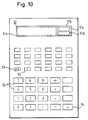
- FIG. 10 shows a conventional portable electronic calculator.
- the LCD 51 comprises a main display area 51a, and a fraction display section 51b which includes a numerator display area 51c and a denominator display area 51d.
- the numerator and denominator of the fraction are displayed on the numerator display area 51c and the denominator display area 51d, respectively.
- the integral part of the mixed fraction is displayed on the main display area 51a.
- a fraction is displayed with both the numerator and denominator aligned to the right.
- the numerator or the denominator looks squeezed to the right on the display as compared with the other, making it difficult for the operator to quickly and correctly recognize the displayed fraction.
- this problem becomes more serious when there is a great difference between the number of digits of the numerator and that of the denominator.
- Figure 12 shows other examples of key operations for inputting fractions and their displayed results.
- rows B and D in Figure 12 in the case of displaying a mixed fraction, the numerator and denominator of the fraction as well as the integral part thereof are right-justified on the LCD 51. This leaves blank space between the integral part and fractional part of the mixed fraction displayed on the LCd 51, making it difficult for the operator to quickly and correctly recognize the mixed fraction on the display.
- a portable electronic calculator calculation results are sometimes obtained and displayed in exponential notation mainly because of a limit to the maximum number of digits available for arithmetical calculations within the calculator.
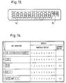
- a conventional calculator has a display such as shown in Figure 13.
- the display of Figure 13 includes a mantissa display section 151 for displaying the mantissa of the number and an exponent display section 152 for displaying the exponent of the number.
- Figure 14 shows examples of key operations on a calculator equipped with the display of Figure 13 and their displayed results.
- Rows A to C in Figure 14 show a sequence for entering a number 1.234567891*10 99 .
- the mantissa (1.234567891) is entered (row A in Figure 14).
- the entered mantissa is displayed on the mantissa display section 151, but since the exponent is not entered yet, nothing is displayed on the exponent display section 152.
- an "EXP" key is pressed, the entry of an exponent is enabled, the enabled state being indicated by "00" on the exponent display section 152 (row B in Figure 14).
- Row C in Figure 14 shows that the entered exponent (99) is displayed on the exponent display section 152.
- Row D in Figure 14 shows a sequence for calculating ⁇ 2 (the square root of 2). Since no exponent results from the calculation, the exponent display section 152 displays nothing.
- Row E in Figure 14 shows a sequence for calculating 69! (the factorial of 69). The calculation result shows 1.711224524 ⁇ 10 98 .
- the mantissa of the result "1.711224524", is displayed on the mantissa display section 151, while the exponent "98" is shown on the exponent display section 152.
- a conventional calculator has a dedicated display section for displaying the exponent of a number expressed in exponential notation.
- US-A-4 545 022 discloses a fractional calculator with a display composed of twelve digits arranged in a row. The first four digits at the right hand side of this display are for the display of fractions, whereby two numerator digits are separated from two denumerator digits by a fraction symbol "/". The integral part of mixed fractions will be displayed in the digit position immediately to the left of the fraction digits.
- the electronic computer of this invention which overcomes the above-discussed and numerous other disadvantages and deficiencies of the prior art, comprises: display means, said display means including a first multiple-digit display area for displaying the numerator of a fraction, and a second multiple-digit display area for displaying the denominator of the fraction; said electronic computer is characterized by means for obtaining the number of digits of the numerator of a fraction to be displayed; means for obtaining the number of digits of the denominator of said fraction; comparison means for comparing said number of digits of said numerator and said number of digits of said denominator; calculation means for calculating the difference between said number of digits of said numerator and said number of digits of said denominator; and means for, when said number of digits of said numerator is smaller than said number of digits of said denominator, displaying said numerator on said first multiple-digit display area with its position shifted to an upper digit place according to the difference calculated by said
- said display means are further comprising: a third multiple-digit display area for displaying the integral part of a mixed fraction; and said electronic computer is further comprising: process means for displaying at least one of the numerator and denominator of a fraction to be displayed, at the position of the corresponding one of said first and second multiple-digit display areas, said position being closest to said third display area.
- said first multiple-digit display area is positioned above said second multiple-digit display area, and said third multiple-digit display area is positioned at the left of said first and second multiple-digit display areas.
- the electronic computer further comprises: process means for, when a number in exponential notation is to be displayed, displaying the exponent of said number on a fraction display section, wherein said fraction display section includes said first multiple-digit display area for displaying the numerator of a fraction and said second multiple-digit display area for displaying the denominator of the fraction, and the exponent of said number is displayed on said first multiple-digit display area.
- Figure 1 shows a portable electronic calculator according to the invention.
- Figure 2 is a block diagram of the calculator of Figure 1.
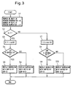
- Figure 3 is a flowchart showing an algorithm for processing the display of a fraction in the calculator of Figure 1.
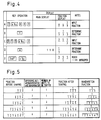
- Figure 4 shows examples of key operations and their displayed results in the calculator of Figure 1.
- Figure 5 shows examples of the display shaping according to the flow of Figure 4.
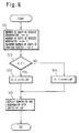
- Figure 6 is a flowchart showing an algorithm for processing the display of a fraction in another embodiment of the invention.
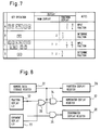
- Figure 7 shows examples of key operations and their displayed results in the other embodiment.
- Figure 8 is a block diagram showing the essential part of a circuit associated with the display of a further embodiment of the invention.
- Figure 9 shows examples of key operations and their displayed results in the further embodiment.
- Figure 10 shows a conventional portable electronic calculator.
- FIG 11 shows examples of key operations and their displayed results in the calculator of Figure 10.
- Figure 12 shows examples of key operations for inputting fractions and their displayed results in a conventional calculator.
- Figure 13 snows a display of a conventional calculator having a mantissa display section.
- Figure 14 shows examples of key operations and their displayed results in the calculator having the display of Figure 13.
- FIG. 1 shows an electronic calculator according to the invention.
- the calculator of Figure 1 is a scientific calculator capable of performing a variety of scientific calculations. With regard to the keys, the following description only deals with the keys related to the entry, display, etc. of fractions.
- the calculator of this embodiment includes a liquid crystal display (LCD) 1 and a keyboard 2.
- the LCD 1 comprises a main display section 1a and a fraction display section 1b for displaying a fraction, etc.
- the numerator is displayed on a numerator display area 1c in the upper part of the fraction display section 1b, and the denominator on a denominator display area 1d in the lower part thereof.
- the integral part of the mixed fraction is displayed on the main display section 1a.
- FIG. 2 shows a block diagram of this embodiment. Coupled to a CPU 21 are a ROM 22 in which programs and constants are held, a RAM 23 for storing control data and numeric data, and a key matrix 26 for detecting key entries from the keyboard 2.
- the LCD 1 is coupled to the CPU 21 via an LCD driving circuit 24 which controls the driving of the LCD 1.
- the integral part of the mixed fraction is entered using the numeric keys 2c, and after pressing the [a b / c ] key 2a to determine the entry of the integral part, the fractional part of the mixed fraction is entered in accordance with the same procedure as for inputting an improper fraction.
- the conversion between improper fraction and mixed fraction is accomplished by pressing the second function key 2d followed by the [a b / c ] key 2a.
- X, Y and DIF respectively indicate variables for storing the number of digits of the denominator after reduction, the number of digits of the numerator after reduction, and the difference between the number of digits of the denominator and that of the numerator.
- a memory location is assigned on the RAM 23 for each of these variables.
- step S1 the numbers of digits of the denominator and numerator are obtained after performing arithmetic operation, reduction, etc. on the fraction entered, and are saved in X and Y respectively (step S1).
- step S2 X and Y are compared, and the process proceeds to step S3 when X is greater than Y, and to step S7 when X is smaller than or equal to Y.
- step S3 the number of digits of the numerator Y is subtracted from that of the denominator X, and the result is saved in DIF.
- step 4 it is judged if DIF is divisible by 2, and when judged divisible, the numerator is displayed on the numerator display area 1c ( Figure 1) with its position shifted to a higher order position, i.e., to the left, by (DIF/2) digits (step S5).
- DIF is judged indivisible by 2
- the numerator is displayed on the numerator display area 1c with its position shifted to the left by ((DIF-1)/2) digits (step S6).
- the processing per steps S5 and S6 is done, the denominator is right-justified on the denominator display area 1d ( Figure 1).
- step S7 the number of digits of the denominator X is subtracted from that of the numerator Y, and the result is saved in DIF.
- step S8 it is judged if DIF is divisible by 2 (step S8), and when judged divisible, the denominator is displayed on the denominator display area Id with its position shifted to the left by (DIF/2) digits (step S9).
- DIF is judged indivisible by 2
- the denominator is displayed on the denominator display area 1d with its position shifted to the left by ((DIF-1)/2) digits (step S10).
- Figure 4 shows examples of key operations according to this embodiment and their displayed results.
- Row E in Figure 4 shows the key operation for conversion from mixed fraction to improper fraction. In this example, since the number of digits of the denominator is smaller than that of the numerator after conversion into the improper fraction, the denominator is displayed with its position shifted to the left.
- the fraction display section 1b is capable of displaying a maximum of three digits for each of the numerator and denominator of a fraction, but when a display is used which can display a fraction having a larger number of digits, display shaping is perforeed as shown in Figure 5 in accordance with the algorithm shown in Figure 3 As can be seen from Figure 5, since the fraction is displayed in a format closer to handwriting, the displayed fraction is that much easier for the operator to recognize.
- Figure 6 shows an algorithm for processing the display of a fraction entered in another calculator according to the invention which has a similar structure as the calculator of Figure 1.
- X, Y and A respectively indicate variables for storing the number of digits of the denominator after reduction, the number of digits of the numerator after reduction, and the maximum number of digits capable of being displayed on the fraction display section 1b.
- a memory location is assigned on the RAM 23 for each of these variables.
- step S21 the numbers of digits of the denominator and numerator are obtained after performing arithmetic operation, reduction, etc., on the fraction entered, and are saved in X and Y respectively (step S21). Further, in step S21, the maximum number of digits capable of being displayed on the fraction display section 1b is obtained and saved in A. Next, in step S22, X and Y are compared, and the process proceeds to step S23 when X is greater than Y, and to step S24 when X is smaller than or equal to Y.
- step S23 the number of digits of the denominator X is subtracted from the maximum number of digits A, and the result is saved in a variable LAP.
- step S24 the number of digits of the numerator Y is subtracted from the maximum number of digits A, and the result is saved in the variable LAP.
- step S25 the denominator or the numerator is displayed on the denominator display area 1d ( Figure 1) or the numerator display area 1c ( Figure 1) with its position shifted to a higher order position, i.e. to the left, by the digits equal to the variable LAP.
- the algorithm shown in Figure 6 can be applied for displaying mixed fractions only or for displaying both mixed fractions and improper fractions.
- Figure 7 shows examples of key operations according to this embodiment and their displayed results.
- the fraction is reduced to the lowest term and converted into a mixed fraction.
- the fractional part of the mixed fraction is left-justified on the fraction display section 1b, in accordance with the algorithm shown in Figure 6, so that it is positioned closest to the main display section 1a.
- Row C in Figure 7 shows the sequence for entering a mixed fraction.
- the fractional part is left-justified on the display.
- the fractional part is reduced to the lowest term.
- both the numerator and the denominator are displayed with their positions shifted by the same number of digits, therefore, the numerator and the denominator on the display are aligned on the right.
- this is not essential for the present invention, and the numerator or the denominator, whichever smaller in the number of digits, may be shifted to the left with respect to the other so that the numerator and the denominator are aligned on the left.
- the electronic calculator of this embodiment can provide improved operability, enabling the operator to quickly recognize the mixed fraction on the display.
- Figure 8 shows the essential part of a circuit associated with the display of a further electronic calculator according to the invention which has a similar structure as the calculator of Figure 1.
- An [EXP] key If is used for entering an exponent, a square root [ ⁇ ] key 2g is used for obtaining the square root of a number, and an [n!] key 2h has a factorial calculation function as the second function. In displaying a number in exponential notation, the mantissa of the number is displayed on the main display section 1a, while the exponent thereof is shown on the fraction display section 1b.
- Numeric data to be displayed is stored in a numeric data storage register 31.
- a fraction display flip-flop 32 is set to output "1" when displaying a fraction, and is reset to output "0" when displaying other types of number.
- An exponent display flip-flop 33 is set when displaying a number in exponential notation, and reset when displaying a number in other notation.
- a display pattern to be displayed on the main display section 1a is stored in a mantissa display register 36.
- a display pattern to be displayed on the numerator display area 1c and a display pattern to be displayed on the denominator display area 1d are respectively stored in a numerator display register 37 and a denominator display register 38.
- the main display section 1a, the numerator display area 1c, and the denominator display area 1d provide displays according to the contents of the mantissa display register 36, numerator display register 37, and denominator display register 38, respectively.
- a gate 39 outputs a "1" if any one of the outputs of the fraction display flip-flop 32 and exponent display flip-flop 33 is " 1".
- a gate 34 allows the data in the numeric data storage register 31 to be transferred to the numerator display register 37 when the output of the gate 39 is "1".
- a gate 35 allows the data in the numeric data storage register 31 to be transferred to the denominator display register 38 when the output of the exponent display flip-flop 33 is "1".
- the fraction display flip-flop 32 is set, and "1" is given from the gate 39 to tie gate 34. This causes the data in the numeric data storage register 31 to be transferred to the numerator display register 37 via the gate 34. Based on this data, a display pattern corresponding to the numerator to be displayed is formed in the numerator display register 37. Since "1" is given from the fraction display flip-flop 32 to the gate 35, the data in the numeric data storage register 31 is transferred to the denominator display register 38 via the gate 35. Based on this data, a display pattern corresponding to the denominator to be displayed is formed in the denominator display register 38. Furthermore, in the case of a mixed fraction, a display pattern corresponding to the integral part of the mixed fraction to be displayed is formed in the mantissa display register 36 based on the data from the numeric data storage register 31.
- the exponent display flip-flop 33 is set, while the fraction display flip-flop 32 is reset. In this state, "1" is input to the gate 34 from the gate 39, and "0" is input to the gate 35 from the fraction display flip-flop 32. Therefore, the data in the numeric data storage register 31 is transferred to the mantissa display register 36 and the numerator display register 37, but not transferred to the denominator display register 38. This means that no display pattern is formed in the denominator display register 38, hence the denominator display area 1d being set in the off condition.
- a display pattern corresponding to the mantissa of the number is formed in the mantissa display register 36 based on the data from the numeric data storage register 31. Also, a display pattern corresponding to the exponent of the number is formed in the numerator display register 37 based on the data from the numeric data storage register 31.
- the fraction display flip-flop 32 and the exponent display flip-flop 33 are both reset. Therefore, the data in the numeric data storage register 31 is not transferred either to the numerator display register 37 or to the denominator display register 38. This means that no display pattern is formed either in the numerator display register 37 or in the denominator display register 38, hence both the numerator display area lc and the denominator display area 1d being set in the off condition.
- a display pattern corresponding to the mantissa of the number is formed in the mantissa display register 36.
- FIG. 9 shows examples of key operations according to this embodiment and their displayed results.
- Rows A and B in Figure 9 show a sequence for entering an improper fraction and a mixed fraction, respectively.
- the numerator and denominator of the improper fraction are displayed on the numerator display area 1c and denominator display area 1d, respectively.
- the integral part of the mixed fraction is displayed on the main display section 1a.
- Rows C to E in Figure 9 show a sequence for entering a number in exponential notation.
- rows D and E in Figure 9 the exponent of the number is displayed on the numerator display area 1c.
- Rows F and G in Figure 9 show a sequence for a square root and a factorial calculation, respectively.
- the numerator display area 1c displays nothing.
- Row G in Figure 9 shows that the exponent of the calculation result is displayed on the numerator display area 1c.
- displaying of a fraction and displaying of a number in exponential notation can be accomplished using a display of simple construction.
Landscapes
- Engineering & Computer Science (AREA)
- Computer Hardware Design (AREA)
- Computing Systems (AREA)
- General Engineering & Computer Science (AREA)
- Theoretical Computer Science (AREA)
- Human Computer Interaction (AREA)
- Physics & Mathematics (AREA)
- General Physics & Mathematics (AREA)
- Calculators And Similar Devices (AREA)
- Digital Computer Display Output (AREA)
Description
- This invention relates to an electronic computer, and more particularly to an electronic computer such as a portable electronic calculator having a display.
- Figure 10 shows a conventional portable electronic calculator. The calculator of Figure 10 comprises a liquid crystal display (LCD) 51, a
fraction entry key 52,numeric keys 53 for entering numbers, an equal [=]key 54, and an [a/b]key 55 for converting a mixed fraction to an improper fraction or vice versa. TheLCD 51 comprises amain display area 51a, and afraction display section 51b which includes anumerator display area 51c and adenominator display area 51d. When a fraction is to be displayed on theLCD 51, the numerator and denominator of the fraction are displayed on thenumerator display area 51c and thedenominator display area 51d, respectively. In the case of displaying a mixed fraction, the integral part of the mixed fraction is displayed on themain display area 51a. - In the calculator of Figure 10, a fraction can be input in the following manner. First, the numerator is entered using the
numeric keys 53, and then thefraction entry key 52 is pressed to determine the entry of the numerator (rows A and C in Figure 11). Next, the denominator is entered, and when the [=]key 54 or another key is pressed, the entry of the denominator is determined while the resulting fraction is reduced to the lowest term if reducible (rows B and D in Figure 11). When the [a/b]key 55 is pressed, the conversion from an improper fraction to a mixed fraction or vice versa is conducted (row E in Figure 11). - In a conventional calculator, as can be seen from rows B and E in Figure 11, a fraction is displayed with both the numerator and denominator aligned to the right. When there is a difference between the number of digits of the numerator and that of the denominator, therefore, the numerator or the denominator, whichever smaller, looks squeezed to the right on the display as compared with the other, making it difficult for the operator to quickly and correctly recognize the displayed fraction. In particular, this problem becomes more serious when there is a great difference between the number of digits of the numerator and that of the denominator.
- Figure 12 shows other examples of key operations for inputting fractions and their displayed results. As shown in rows B and D in Figure 12, in the case of displaying a mixed fraction, the numerator and denominator of the fraction as well as the integral part thereof are right-justified on the
LCD 51. This leaves blank space between the integral part and fractional part of the mixed fraction displayed on theLCd 51, making it difficult for the operator to quickly and correctly recognize the mixed fraction on the display. - On the other hand, in a portable electronic calculator, calculation results are sometimes obtained and displayed in exponential notation mainly because of a limit to the maximum number of digits available for arithmetical calculations within the calculator. To display a number, obtained as a result of an arithmetical calculation, etc., in exponential notation, a conventional calculator has a display such as shown in Figure 13. The display of Figure 13 includes a
mantissa display section 151 for displaying the mantissa of the number and anexponent display section 152 for displaying the exponent of the number. - Figure 14 shows examples of key operations on a calculator equipped with the display of Figure 13 and their displayed results. Rows A to C in Figure 14 show a sequence for entering a number 1.234567891*1099. First, the mantissa (1.234567891) is entered (row A in Figure 14). In this state, the entered mantissa is displayed on the
mantissa display section 151, but since the exponent is not entered yet, nothing is displayed on theexponent display section 152. Next, when an "EXP" key is pressed, the entry of an exponent is enabled, the enabled state being indicated by "00" on the exponent display section 152 (row B in Figure 14). Row C in Figure 14 shows that the entered exponent (99) is displayed on theexponent display section 152. Row D in Figure 14 shows a sequence for calculating √2 (the square root of 2). Since no exponent results from the calculation, theexponent display section 152 displays nothing. Row E in Figure 14 shows a sequence for calculating 69! (the factorial of 69). The calculation result shows 1.711224524∗1098. As shown in row E in Figure 14, the mantissa of the result, "1.711224524", is displayed on themantissa display section 151, while the exponent "98" is shown on theexponent display section 152. - As described above, a conventional calculator has a dedicated display section for displaying the exponent of a number expressed in exponential notation. On the other hand, in the field of calculators, it is desirable that fractions be displayed in a format closer to the usual representation in order to enhance operability. If a conventional calculator is to be further equipped with a display section for displaying a fraction, however, the problem is that the entire display will become complicated and expensive in construction.
- US-A-4 545 022 discloses a fractional calculator with a display composed of twelve digits arranged in a row. The first four digits at the right hand side of this display are for the display of fractions, whereby two numerator digits are separated from two denumerator digits by a fraction symbol "/".The integral part of mixed fractions will be displayed in the digit position immediately to the left of the fraction digits.
- In Patent Abstracts of Japan, vol.13, no.245 (P-881) (3593) June 1989, & JP-A-146 828 a numerical value display part is disclosed, that is divided into upper and lower areas. In a normal numerical value input/arithmetic mode, only the lower part of the display is used, while in a fractional arithmetic mode, the denominator is displayed in the lower part of the display and the numerator is displayed in the upper part of the display.
- The electronic computer of this invention, which overcomes the above-discussed and numerous other disadvantages and deficiencies of the prior art, comprises: display means, said display means including a first multiple-digit display area for displaying the numerator of a fraction, and a second multiple-digit display area for displaying the denominator of the fraction; said electronic computer is characterized by means for obtaining the number of digits of the numerator of a fraction to be displayed; means for obtaining the number of digits of the denominator of said fraction; comparison means for comparing said number of digits of said numerator and said number of digits of said denominator; calculation means for calculating the difference between said number of digits of said numerator and said number of digits of said denominator; and means for, when said number of digits of said numerator is smaller than said number of digits of said denominator, displaying said numerator on said first multiple-digit display area with its position shifted to an upper digit place according to the difference calculated by said calculation means, and for, when said number of digits of said denominator is smaller than said number of digits of said numerator, displaying said denominator on said second multiple-digit display area with its position shifted to an upper digit place according to the difference calculated by said calculation means, whereby the numerator is displayed above the denominator.
- In a preferred embodiment, said display means are further comprising: a third multiple-digit display area for displaying the integral part of a mixed fraction; and said electronic computer is further comprising: process means for displaying at least one of the numerator and denominator of a fraction to be displayed, at the position of the corresponding one of said first and second multiple-digit display areas, said position being closest to said third display area.
- In the computer, said first multiple-digit display area is positioned above said second multiple-digit display area, and said third multiple-digit display area is positioned at the left of said first and second multiple-digit display areas.
- In a further preferred embodiment, the electronic computer further comprises: process means for, when a number in exponential notation is to be displayed, displaying the exponent of said number on a fraction display section, wherein said fraction display section includes said first multiple-digit display area for displaying the numerator of a fraction and said second multiple-digit display area for displaying the denominator of the fraction, and the exponent of said number is displayed on said first multiple-digit display area.
- Thus, the invention described herein makes possible the objectives of:
- (1) providing an electronic computer which is capable of displaying a fraction in such a manner that the operator can quickly recognize the fraction;
- (2) providing an electronic computer which is capable of displaying a fraction in such a manner that the operator can correctly recognize the fraction;
- (3) providing an electronic computer which is capable of displaying a mixed fraction in such a manner that the operator can quickly recognize the mixed fraction;
- (4) providing an electronic computer which is capable of displaying a mixed fraction in such a manner that the operator can correctly recognize the mixed fraction; and
- (5) providing an electronic computer which is capable of displaying a fraction as well as a number expressed in exponential notation using a display of simple construction.
- This invention may be better understood and its numerous objects and advantages will become apparent to those skilled in the art by reference to the accompanying drawings as follows:
- Figure 1 shows a portable electronic calculator according to the invention.
- Figure 2 is a block diagram of the calculator of Figure 1.
- Figure 3 is a flowchart showing an algorithm for processing the display of a fraction in the calculator of Figure 1.
- Figure 4 shows examples of key operations and their displayed results in the calculator of Figure 1.
- Figure 5 shows examples of the display shaping according to the flow of Figure 4.
- Figure 6 is a flowchart showing an algorithm for processing the display of a fraction in another embodiment of the invention.
- Figure 7 shows examples of key operations and their displayed results in the other embodiment.
- Figure 8 is a block diagram showing the essential part of a circuit associated with the display of a further embodiment of the invention.
- Figure 9 shows examples of key operations and their displayed results in the further embodiment.
- Figure 10 shows a conventional portable electronic calculator.
- Figure 11 shows examples of key operations and their displayed results in the calculator of Figure 10.
- Figure 12 shows examples of key operations for inputting fractions and their displayed results in a conventional calculator.
- Figure 13 snows a display of a conventional calculator having a mantissa display section.
- Figure 14 shows examples of key operations and their displayed results in the calculator having the display of Figure 13.
- Figure 1 shows an electronic calculator according to the invention. The calculator of Figure 1 is a scientific calculator capable of performing a variety of scientific calculations. With regard to the keys, the following description only deals with the keys related to the entry, display, etc. of fractions. The calculator of this embodiment includes a liquid crystal display (LCD) 1 and a
keyboard 2. TheLCD 1 comprises amain display section 1a and afraction display section 1b for displaying a fraction, etc. In displaying an improper fraction, the numerator is displayed on anumerator display area 1c in the upper part of thefraction display section 1b, and the denominator on adenominator display area 1d in the lower part thereof. In the case of a mixed fraction, the integral part of the mixed fraction is displayed on themain display section 1a. Thekeyboard 2 comprises an [ab/c] key 2a for converting a mixed fraction to an improper fraction or vice versa, asecond function key 2b for choosing functions of the [ab/c] key 2a and other keys,numeral keys 2c for entering thenumbers 0 to 9,arithmetic function keys 2d for performing arithmetic, and an equal [=] key 2e. - Figure 2 shows a block diagram of this embodiment. Coupled to a
CPU 21 are aROM 22 in which programs and constants are held, aRAM 23 for storing control data and numeric data, and akey matrix 26 for detecting key entries from thekeyboard 2. TheLCD 1 is coupled to theCPU 21 via anLCD driving circuit 24 which controls the driving of theLCD 1. - The manner of inputting a fraction in the calculator of Figure 1 will be described. When an improper fraction is to be input, first the numerator is entered using the
numeric keys 2c, and then, the [ab/c] key 2a is pressed to determine the entry of the numerator. Next, the denominator is entered using thenumeric keys 2c, and the entry of the fraction is determined when any of thearithmetic function keys 2d, the equal key 2e, etc. is pressed. To input a mixed fraction, first the integral part of the mixed fraction is entered using thenumeric keys 2c, and after pressing the [ab/c] key 2a to determine the entry of the integral part, the fractional part of the mixed fraction is entered in accordance with the same procedure as for inputting an improper fraction. At the same time that the entry of a fraction is determined by pressing thearithmetic function keys 2d, the equal [=]key 2e, etc., the fraction is reduced to the lowest term if reducible, and converted into a mixed fraction if convertible. The conversion between improper fraction and mixed fraction is accomplished by pressing thesecond function key 2d followed by the [ab/c] key 2a. - Figure 3 shows an algorithm for processing the display of a fraction entered by pressing the
arithmetic function keys 2d, the equal [=]key 2e, etc. In Figure 3, X, Y and DIF respectively indicate variables for storing the number of digits of the denominator after reduction, the number of digits of the numerator after reduction, and the difference between the number of digits of the denominator and that of the numerator. A memory location is assigned on theRAM 23 for each of these variables. - First, the numbers of digits of the denominator and numerator are obtained after performing arithmetic operation, reduction, etc. on the fraction entered, and are saved in X and Y respectively (step S1). Next, in step S2, X and Y are compared, and the process proceeds to step S3 when X is greater than Y, and to step S7 when X is smaller than or equal to Y.
- In step S3, the number of digits of the numerator Y is subtracted from that of the denominator X, and the result is saved in DIF. In
step 4, it is judged if DIF is divisible by 2, and when judged divisible, the numerator is displayed on thenumerator display area 1c (Figure 1) with its position shifted to a higher order position, i.e., to the left, by (DIF/2) digits (step S5). When DIF is judged indivisible by 2, the numerator is displayed on thenumerator display area 1c with its position shifted to the left by ((DIF-1)/2) digits (step S6). When the processing per steps S5 and S6 is done, the denominator is right-justified on thedenominator display area 1d (Figure 1). - In step S7, the number of digits of the denominator X is subtracted from that of the numerator Y, and the result is saved in DIF. Next, it is judged if DIF is divisible by 2 (step S8), and when judged divisible, the denominator is displayed on the denominator display area Id with its position shifted to the left by (DIF/2) digits (step S9). When DIF is judged indivisible by 2, the denominator is displayed on the
denominator display area 1d with its position shifted to the left by ((DIF-1)/2) digits (step S10). When the processing per steps S9 and S10 is done, the numerator is right-justified on thenumerator display section 1c - Figure 4 shows examples of key operations according to this embodiment and their displayed results. A fraction entered as shown in row A in Figure 4 is determined by pressing the equal [=]
key 2e, and, at the same time, reduced to the lowest term as shown in row B in Figure 4. Since the number of digits of the numerator to be displayed is smaller than that of the denominator, the numerator is displayed with its position shifted to the left so that the numerator is centered with respect to the denominator. As shown in rows C and D in figure 4, when the numerator of the entered fraction is greater than the denominator, the entered fraction is converted into a mixed fraction when the equal [=]key 2e is pressed to determine the entry. Row E in Figure 4 shows the key operation for conversion from mixed fraction to improper fraction. In this example, since the number of digits of the denominator is smaller than that of the numerator after conversion into the improper fraction, the denominator is displayed with its position shifted to the left. - In this embodiment, the
fraction display section 1b is capable of displaying a maximum of three digits for each of the numerator and denominator of a fraction, but when a display is used which can display a fraction having a larger number of digits, display shaping is perforeed as shown in Figure 5 in accordance with the algorithm shown in Figure 3 As can be seen from Figure 5, since the fraction is displayed in a format closer to handwriting, the displayed fraction is that much easier for the operator to recognize. - Figure 6 shows an algorithm for processing the display of a fraction entered in another calculator according to the invention which has a similar structure as the calculator of Figure 1. In Figure 6, X, Y and A respectively indicate variables for storing the number of digits of the denominator after reduction, the number of digits of the numerator after reduction, and the maximum number of digits capable of being displayed on the
fraction display section 1b. A memory location is assigned on theRAM 23 for each of these variables. - First, the numbers of digits of the denominator and numerator are obtained after performing arithmetic operation, reduction, etc., on the fraction entered, and are saved in X and Y respectively (step S21). Further, in step S21, the maximum number of digits capable of being displayed on the
fraction display section 1b is obtained and saved in A. Next, in step S22, X and Y are compared, and the process proceeds to step S23 when X is greater than Y, and to step S24 when X is smaller than or equal to Y. - In step S23, the number of digits of the denominator X is subtracted from the maximum number of digits A, and the result is saved in a variable LAP. In step S24, the number of digits of the numerator Y is subtracted from the maximum number of digits A, and the result is saved in the variable LAP. As a result of processing per S22 and S23 or S24, the result obtained by subtracting the number of digits of the denominator X or that of the numerator Y, whichever greater, from the maximum number of digits A is saved in the variable LAP. In step S25, the denominator or the numerator is displayed on the
denominator display area 1d (Figure 1) or thenumerator display area 1c (Figure 1) with its position shifted to a higher order position, i.e. to the left, by the digits equal to the variable LAP. - The algorithm shown in Figure 6 can be applied for displaying mixed fractions only or for displaying both mixed fractions and improper fractions.
- Figure 7 shows examples of key operations according to this embodiment and their displayed results. A fraction entered as shown in row A in Figure 7 is determined by pressing the equal [=] key 2e as shown in
row 9 in Figure 7. At the same time, the fraction is reduced to the lowest term and converted into a mixed fraction. Also, the fractional part of the mixed fraction is left-justified on thefraction display section 1b, in accordance with the algorithm shown in Figure 6, so that it is positioned closest to themain display section 1a. Row C in Figure 7 shows the sequence for entering a mixed fraction. When the entry of the mixed fraction is determined by pressing the equal [=] key 2e as shown in row D in Figure 7, the fractional part is left-justified on the display. In row D in Figure 7 also, the fractional part is reduced to the lowest term. - In the above embodiment, as can be seen from the flowchart of figure 6, both the numerator and the denominator are displayed with their positions shifted by the same number of digits, therefore, the numerator and the denominator on the display are aligned on the right. However, this is not essential for the present invention, and the numerator or the denominator, whichever smaller in the number of digits, may be shifted to the left with respect to the other so that the numerator and the denominator are aligned on the left.
- Since the fractional part and integral part of a mixed fraction are displayed without leaving blank space between them, the electronic calculator of this embodiment can provide improved operability, enabling the operator to quickly recognize the mixed fraction on the display.
- Figure 8 shows the essential part of a circuit associated with the display of a further electronic calculator according to the invention which has a similar structure as the calculator of Figure 1. Before describing the circuit shown in Figure 8, the keys which are necessary for describing this embodiment but have not yet described in the description of the foregoing embodiments will be described. An [EXP] key If is used for entering an exponent, a square root [√] key 2g is used for obtaining the square root of a number, and an [n!] key 2h has a factorial calculation function as the second function. In displaying a number in exponential notation, the mantissa of the number is displayed on the
main display section 1a, while the exponent thereof is shown on thefraction display section 1b. - Referring to Figure 8, Numeric data to be displayed is stored in a numeric
data storage register 31. A fraction display flip-flop 32 is set to output "1" when displaying a fraction, and is reset to output "0" when displaying other types of number. An exponent display flip-flop 33 is set when displaying a number in exponential notation, and reset when displaying a number in other notation. A display pattern to be displayed on themain display section 1a is stored in amantissa display register 36. A display pattern to be displayed on thenumerator display area 1c and a display pattern to be displayed on thedenominator display area 1d are respectively stored in anumerator display register 37 and adenominator display register 38. In other words, themain display section 1a, thenumerator display area 1c, and thedenominator display area 1d provide displays according to the contents of themantissa display register 36,numerator display register 37, anddenominator display register 38, respectively. Agate 39 outputs a "1" if any one of the outputs of the fraction display flip-flop 32 and exponent display flip-flop 33 is " 1". Agate 34 allows the data in the numericdata storage register 31 to be transferred to thenumerator display register 37 when the output of thegate 39 is "1". Agate 35 allows the data in the numericdata storage register 31 to be transferred to thedenominator display register 38 when the output of the exponent display flip-flop 33 is "1". - The operation of the circuit of Figure 8 will be described. To display a fraction, first the fraction display flip-
flop 32 is set, and "1" is given from thegate 39 to tiegate 34. This causes the data in the numericdata storage register 31 to be transferred to thenumerator display register 37 via thegate 34. Based on this data, a display pattern corresponding to the numerator to be displayed is formed in thenumerator display register 37. Since "1" is given from the fraction display flip-flop 32 to thegate 35, the data in the numericdata storage register 31 is transferred to thedenominator display register 38 via thegate 35. Based on this data, a display pattern corresponding to the denominator to be displayed is formed in thedenominator display register 38. Furthermore, in the case of a mixed fraction, a display pattern corresponding to the integral part of the mixed fraction to be displayed is formed in the mantissa display register 36 based on the data from the numericdata storage register 31. - To display a number in exponential notation, the exponent display flip-
flop 33 is set, while the fraction display flip-flop 32 is reset. In this state, "1" is input to thegate 34 from thegate 39, and "0" is input to thegate 35 from the fraction display flip-flop 32. Therefore, the data in the numericdata storage register 31 is transferred to themantissa display register 36 and thenumerator display register 37, but not transferred to thedenominator display register 38. This means that no display pattern is formed in thedenominator display register 38, hence thedenominator display area 1d being set in the off condition. A display pattern corresponding to the mantissa of the number is formed in the mantissa display register 36 based on the data from the numericdata storage register 31. Also, a display pattern corresponding to the exponent of the number is formed in the numerator display register 37 based on the data from the numericdata storage register 31. - To display a number with no exponent, the fraction display flip-
flop 32 and the exponent display flip-flop 33 are both reset. Therefore, the data in the numericdata storage register 31 is not transferred either to the numerator display register 37 or to thedenominator display register 38. This means that no display pattern is formed either in the numerator display register 37 or in thedenominator display register 38, hence both the numerator display area lc and thedenominator display area 1d being set in the off condition. On the other hand, a display pattern corresponding to the mantissa of the number is formed in themantissa display register 36. - Figure shows examples of key operations according to this embodiment and their displayed results. Rows A and B in Figure 9 show a sequence for entering an improper fraction and a mixed fraction, respectively. As shown in row A in Figure 9, the numerator and denominator of the improper fraction are displayed on the
numerator display area 1c anddenominator display area 1d, respectively. As shown in row B in Figure 9, in the case of a mixed fraction, the integral part of the mixed fraction is displayed on themain display section 1a. Rows C to E in Figure 9 show a sequence for entering a number in exponential notation. As shown in rows D and E in Figure 9, the exponent of the number is displayed on thenumerator display area 1c. Rows F and G in Figure 9 show a sequence for a square root and a factorial calculation, respectively. In row F in Figure 9, since no exponent results from the calculation, thenumerator display area 1c displays nothing. Row G in Figure 9 shows that the exponent of the calculation result is displayed on thenumerator display area 1c. - According to this embodiment, displaying of a fraction and displaying of a number in exponential notation can be accomplished using a display of simple construction.
- It is understood that various other modifications will be apparent to and can be readily made by those skilled in the art.
Claims (4)
- An electronic computer comprising:display means (1), said display means including a first multiple-digit display area (lc) for displaying the numerator of a fraction, and a second multiple-digit display area (ld) for displaying the denumerator of the fraction; said electronic computer is characterized bymeans (21, 22, 23) for obtaining the number of digits of the numerator of a fraction to be displayed;means (21, 22, 23) for obtaining the number of digits of the denominator of said fraction;comparison means (21, 22, 23) for comparing said number of digits of said numerator and said number of digits of said denominator;calculation means (21, 22, 23) for calculating the difference between said number of digits of said numerator and said number of digits of said denominator; andmeans (21, 24) for, when said number of digits of said numerator is smaller than said number of digits of said denominator, displaying said numerator on said first multiple-digit display area (lc) with its position shifted to an upper digit place according to the difference calculated by said calculation means (21, 22, 23), and for, when said number of digits of said denominator is smaller than said number of digits of said numerator, displaying said denominator on said second multiple-digit display area (1d) with its position shifted to an upper digit place according to the difference calculated by said calculation means (21, 22,23), whereby the numerator is displayed above the denominator.
- An electronic computer according to claim 1, characterized in that said display means (1) are further comprising:a third multiple-digit display area (1a) for displaying the integral part of a mixed fraction; and said electronic computer is further comprising:process means (21, 22, 23, 24) for displaying at least one of the numerator and denominator of a fraction to be displayed, at the position of the corresponding one of said first and second multiple-digit display areas (1c, 1d), said position being closest to said third display area (1a).
- An electronic computer according to claim 2, wherein said first multiple-digit display area (1c) is positioned above said second multiple-digit display area (1d), and said third multiple-digit display area (1a) is positioned at the left of said first and second multiple-digit display areas (1c, 1d).
- An electronic computer according to claim 1, further comprising:
process means (31, 32, 33, 34, 35, 37, 39) for, when a number in exponential notation is to be displayed, displaying the exponent of said number on a fraction display section (1b), wherein said fraction display section (1b) includes said first multiple-digit display area (1c) for displaying the numerator of a fraction and said second multiple-digit display area (1d) for displaying the denominator of the fraction, and the exponent of said number is displayed on said first multiple-digit display area (1c).
Applications Claiming Priority (6)
| Application Number | Priority Date | Filing Date | Title |
|---|---|---|---|
| JP25838589A JPH0786858B2 (en) | 1989-10-02 | 1989-10-02 | Electronic computer |
| JP258385/89 | 1989-10-02 | ||
| JP1258386A JP2571856B2 (en) | 1989-10-02 | 1989-10-02 | Electronic computer |
| JP258384/89 | 1989-10-02 | ||
| JP25838489A JPH03119454A (en) | 1989-10-02 | 1989-10-02 | Electronic computer |
| JP258386/89 | 1989-10-02 |
Publications (3)
| Publication Number | Publication Date |
|---|---|
| EP0421351A2 EP0421351A2 (en) | 1991-04-10 |
| EP0421351A3 EP0421351A3 (en) | 1991-10-30 |
| EP0421351B1 true EP0421351B1 (en) | 1997-07-09 |
Family
ID=27334719
Family Applications (1)
| Application Number | Title | Priority Date | Filing Date |
|---|---|---|---|
| EP90118875A Expired - Lifetime EP0421351B1 (en) | 1989-10-02 | 1990-10-02 | An electronic computer |
Country Status (4)
| Country | Link |
|---|---|
| US (1) | US5241489A (en) |
| EP (1) | EP0421351B1 (en) |
| CA (1) | CA2026637C (en) |
| DE (1) | DE69031021T2 (en) |
Families Citing this family (5)
| Publication number | Priority date | Publication date | Assignee | Title |
|---|---|---|---|---|
| DE29504576U1 (en) * | 1995-03-07 | 1995-05-11 | Francotyp-Postalia GmbH, 16547 Birkenwerder | Print head thermal control |
| JP3088299B2 (en) * | 1996-08-15 | 2000-09-18 | 静岡日本電気株式会社 | Portable radio |
| US7325020B2 (en) * | 2003-08-08 | 2008-01-29 | Hewlett-Packard Development Company, L.P. | Input and evaluation of fractions using a calculator |
| US20070256036A1 (en) * | 2006-04-28 | 2007-11-01 | Johnson Eric S | User interface having integer and fraction display |
| CN112463117B (en) * | 2020-11-23 | 2024-07-09 | 江苏卓胜微电子股份有限公司 | Method, device, equipment and storage medium for representing fractions with random bit sequence |
Family Cites Families (9)
| Publication number | Priority date | Publication date | Assignee | Title |
|---|---|---|---|---|
| JPS53126218A (en) * | 1977-04-11 | 1978-11-04 | Toshiba Corp | Unit and system for display |
| JPS5580862A (en) * | 1978-12-12 | 1980-06-18 | Seiko Epson Corp | Aural album |
| US4488250A (en) * | 1982-07-02 | 1984-12-11 | Lipsey William S | Hand-held calculator for performing calculations in feet, inches and fractions |
| US4545022A (en) * | 1983-02-10 | 1985-10-01 | Hughins James T | Fractional calculator |
| US4744044A (en) * | 1986-06-20 | 1988-05-10 | Electronic Teacher's Aids, Inc. | Hand-held calculator for dimensional calculations |
| US4800514A (en) * | 1987-05-28 | 1989-01-24 | Earle John R | Electronic graphic arts proportional calculator |
| JPS6446828A (en) * | 1987-08-17 | 1989-02-21 | Nec Corp | Numerical value display part |
| US5025403A (en) * | 1989-10-30 | 1991-06-18 | Hewlett-Packard Company | Fraction entry and display |
| US5067102A (en) * | 1990-01-31 | 1991-11-19 | Hewlett-Packard Company | Method and apparatus for displaying and editing mathematical expressions in textbook format |
-
1990
- 1990-09-28 US US07/589,656 patent/US5241489A/en not_active Expired - Lifetime
- 1990-10-01 CA CA002026637A patent/CA2026637C/en not_active Expired - Lifetime
- 1990-10-02 EP EP90118875A patent/EP0421351B1/en not_active Expired - Lifetime
- 1990-10-02 DE DE69031021T patent/DE69031021T2/en not_active Expired - Fee Related
Also Published As
| Publication number | Publication date |
|---|---|
| DE69031021D1 (en) | 1997-08-14 |
| US5241489A (en) | 1993-08-31 |
| CA2026637A1 (en) | 1991-04-03 |
| EP0421351A2 (en) | 1991-04-10 |
| EP0421351A3 (en) | 1991-10-30 |
| DE69031021T2 (en) | 1998-01-02 |
| CA2026637C (en) | 1995-02-28 |
Similar Documents
| Publication | Publication Date | Title |
|---|---|---|
| US5089980A (en) | Double keystroke fraction entry and interface method | |
| JPH0850525A (en) | Formula input device | |
| US5241489A (en) | Electronic computer with fraction and exponent display | |
| EP0126286B1 (en) | Electronic cash register | |
| US4567567A (en) | Computer keyboard displaying many operating instructions with few keys | |
| EP0490875B1 (en) | Electronic calculator | |
| US4680725A (en) | Dual function decimal key | |
| GB2137002A (en) | Electronic Scale | |
| JPH03119454A (en) | Electronic computer | |
| JP3252493B2 (en) | Electronic calculator and its calculation processing method | |
| CA1173164A (en) | Fraction calculator | |
| JPH0786858B2 (en) | Electronic computer | |
| JP2564742B2 (en) | Electronic data processor | |
| JPS6243227B2 (en) | ||
| JP2571856B2 (en) | Electronic computer | |
| US4779219A (en) | Electronic apparatus having an improved calculation function | |
| US4651295A (en) | Electronic desk-top calculator | |
| JPS642179Y2 (en) | ||
| JPH0435775B2 (en) | ||
| US6865586B2 (en) | Calculator capable of recovering cleared values | |
| JP3521919B2 (en) | Calculator and fraction input and display method in calculator | |
| JPS6022418Y2 (en) | Key-input electronic equipment | |
| JP3684640B2 (en) | Vending machine display device | |
| JPS581462B2 (en) | Index display method | |
| JPH07191834A (en) | Power calculation device |
Legal Events
| Date | Code | Title | Description |
|---|---|---|---|
| PUAI | Public reference made under article 153(3) epc to a published international application that has entered the european phase |
Free format text: ORIGINAL CODE: 0009012 |
|
| 17P | Request for examination filed |
Effective date: 19901221 |
|
| AK | Designated contracting states |
Kind code of ref document: A2 Designated state(s): DE FR GB |
|
| PUAL | Search report despatched |
Free format text: ORIGINAL CODE: 0009013 |
|
| AK | Designated contracting states |
Kind code of ref document: A3 Designated state(s): DE FR GB |
|
| 17Q | First examination report despatched |
Effective date: 19960117 |
|
| GRAG | Despatch of communication of intention to grant |
Free format text: ORIGINAL CODE: EPIDOS AGRA |
|
| GRAH | Despatch of communication of intention to grant a patent |
Free format text: ORIGINAL CODE: EPIDOS IGRA |
|
| GRAH | Despatch of communication of intention to grant a patent |
Free format text: ORIGINAL CODE: EPIDOS IGRA |
|
| GRAA | (expected) grant |
Free format text: ORIGINAL CODE: 0009210 |
|
| AK | Designated contracting states |
Kind code of ref document: B1 Designated state(s): DE FR GB |
|
| REF | Corresponds to: |
Ref document number: 69031021 Country of ref document: DE Date of ref document: 19970814 |
|
| ET | Fr: translation filed | ||
| PLBE | No opposition filed within time limit |
Free format text: ORIGINAL CODE: 0009261 |
|
| STAA | Information on the status of an ep patent application or granted ep patent |
Free format text: STATUS: NO OPPOSITION FILED WITHIN TIME LIMIT |
|
| 26N | No opposition filed | ||
| REG | Reference to a national code |
Ref country code: GB Ref legal event code: IF02 |
|
| PGFP | Annual fee paid to national office [announced via postgrant information from national office to epo] |
Ref country code: DE Payment date: 20081014 Year of fee payment: 19 |
|
| PGFP | Annual fee paid to national office [announced via postgrant information from national office to epo] |
Ref country code: FR Payment date: 20081014 Year of fee payment: 19 |
|
| PGFP | Annual fee paid to national office [announced via postgrant information from national office to epo] |
Ref country code: GB Payment date: 20081001 Year of fee payment: 19 |
|
| REG | Reference to a national code |
Ref country code: FR Ref legal event code: ST Effective date: 20100630 |
|
| PG25 | Lapsed in a contracting state [announced via postgrant information from national office to epo] |
Ref country code: FR Free format text: LAPSE BECAUSE OF NON-PAYMENT OF DUE FEES Effective date: 20091102 Ref country code: DE Free format text: LAPSE BECAUSE OF NON-PAYMENT OF DUE FEES Effective date: 20100501 |
|
| PG25 | Lapsed in a contracting state [announced via postgrant information from national office to epo] |
Ref country code: GB Free format text: LAPSE BECAUSE OF NON-PAYMENT OF DUE FEES Effective date: 20091002 |