EP0421045B1 - Back support with integral carrying case - Google Patents
Back support with integral carrying case Download PDFInfo
- Publication number
- EP0421045B1 EP0421045B1 EP90100787A EP90100787A EP0421045B1 EP 0421045 B1 EP0421045 B1 EP 0421045B1 EP 90100787 A EP90100787 A EP 90100787A EP 90100787 A EP90100787 A EP 90100787A EP 0421045 B1 EP0421045 B1 EP 0421045B1
- Authority
- EP
- European Patent Office
- Prior art keywords
- straps
- back support
- user
- support member
- knees
- Prior art date
- Legal status (The legal status is an assumption and is not a legal conclusion. Google has not performed a legal analysis and makes no representation as to the accuracy of the status listed.)
- Expired - Lifetime
Links
Images

Classifications
-
- A—HUMAN NECESSITIES
- A47—FURNITURE; DOMESTIC ARTICLES OR APPLIANCES; COFFEE MILLS; SPICE MILLS; SUCTION CLEANERS IN GENERAL
- A47C—CHAIRS; SOFAS; BEDS
- A47C4/00—Foldable, collapsible or dismountable chairs
- A47C4/52—Trunk chairs, i.e. chairs collapsible to self contained carrying case, e.g. trunk shape
-
- A—HUMAN NECESSITIES
- A47—FURNITURE; DOMESTIC ARTICLES OR APPLIANCES; COFFEE MILLS; SPICE MILLS; SUCTION CLEANERS IN GENERAL
- A47C—CHAIRS; SOFAS; BEDS
- A47C16/00—Stand-alone rests or supports for feet, legs, arms, back or head
Definitions
- the present invention relates to a back support apparatus according to the preamble of claim 1.
- a back support apparatus according to the preamble of claim 1 is known from US-A-4,773,106.
- the object underlying the invention is to facilitate carrying of the apparatus when used for various activities as described herein above.
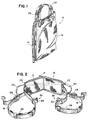
- Figure 1 is a perspective view of the back support with integral carrying case in the closed position.
- Figure 2 is a perspective view of the invention in the open position with the straps extended.
- Figure 3 is a perspective view of the back support in use.
- Figure 4 is a perspective view of the back support being carried by a user in an non-use position.
- the back support and integral carrying case 10 of the present invention is shown in the open position in Figure 2 and includes a back support member 12 having an elongated and generally rectangular shape.
- the outer periphery of the support member 12 is provided with a suitable closure means 14 which, in the preferred embodiment, would be a zipper or similar mechanical closure.
- the support member 12 may be cushioned or padded and/or reinforced thus providing sufficient strength to support the wearer's lower back in use.
- the back support 10 is provided with a pair of elongated straps 16 and 18 which are integrally attached to the support member 12 at respective ends 20 and 22.
- the straps 16 and 18 form elongated loops and include buckle means 24 and 26 which permit adjustment of the length of each of the loops and which also provide a closure for securing the loops in their operative position.
- the straps may extend within the interior layers of the back support member 12 connecting each of the strap components 16 and 18 together. It will also be appreciated that the ends of each of the straps may terminate at the ends 20 and 22 of the back support member 12 as long as the mechanical connection between the straps and the support member is of sufficient strength to withstand the forces subjected to it during use.
- Handle members 28 and 29 are provided to carry the support when it is folded upon itself to form the integral carrying case as shown in Figure 1. In the closed position, the straps 16 and 18 are maintained within the case formed by the back support member 12.
- the straps 16 and 18 are also provided with knee pads 36 and 38 which lessen the strain on the user's knees, permitting him to exert sufficient force on the support member 12 to hold the back in a supported position.
- the back support 10 also includes a retainer strap 40 which is adapted to encircle the torso of a user and to be secured in place by a suitable means such as a buckle 42 so that the back support may be worn on the user without the necessity of having the elongated straps looped over the knees to maintain the support in place. Whereas this does not provide any supporting function, it eliminates the need for repositioning the support each time that it is used and facilitates carrying the back support without the need of a separate carrying case or without continuously holding the item.
- a user is shown wearing the back support.
- the support member 12 is fit against the lumbar portion of the back, and straps 16 and 18 are looped over the knees with the user in a seated position.
- the buckle 30 keeps the knees of the user together. Force, exerted by the knees, pulls the support member against the lumbar region of the wearer's back to provide suitable support.
- the straps are folded into the integrally formed carrying case as described hereinabove.
- Figure 4 illustrates the back support in a non-use position where the retainer strap 40 maintains the strap in the proper position.
Abstract
Description
- The present invention relates to a back support apparatus according to the preamble of claim 1.
- In activities where an individual must be seated upright on a flat surface without a rigid back support, for example on the ground or floor, or on a backless chair, bench, and the like, sitting in this position for extended periods of time is uncomfortable, often painful and difficult, particularly for individuals with back problems. Such activities may include, but are not necessarily limited to, athletic events such as hunting, boating, camping and so forth. Other passive events such as watching athletic contests, meditating and even listening to music may cause back strain when one position is maintained for a considerable length of time. Back supporting apparatus which are generally similar to the present invention are shown in US-Patents 4,773,106 and 4,813,080, and in Japanese Serial Number 63-251009, among others.
- A back support apparatus according to the preamble of claim 1 is known from US-A-4,773,106. The object underlying the invention is to facilitate carrying of the apparatus when used for various activities as described herein above.
- This object is solved by the features in the characterizing clause of claim 1.
- Advantageous developments of this apparatus are stated in the sub-claims.
- Figure 1 is a perspective view of the back support with integral carrying case in the closed position.
- Figure 2 is a perspective view of the invention in the open position with the straps extended.
- Figure 3 is a perspective view of the back support in use.
- Figure 4 is a perspective view of the back support being carried by a user in an non-use position.
- Referring to the drawings, the back support and
integral carrying case 10 of the present invention is shown in the open position in Figure 2 and includes aback support member 12 having an elongated and generally rectangular shape. The outer periphery of thesupport member 12 is provided with a suitable closure means 14 which, in the preferred embodiment, would be a zipper or similar mechanical closure. Thesupport member 12 may be cushioned or padded and/or reinforced thus providing sufficient strength to support the wearer's lower back in use. Theback support 10 is provided with a pair ofelongated straps support member 12 atrespective ends straps back support member 12 connecting each of thestrap components ends back support member 12 as long as the mechanical connection between the straps and the support member is of sufficient strength to withstand the forces subjected to it during use. -
Handle members straps back support member 12. - A
snap type buckle 30, formed of amale locking member 32 and afemale locking member 34, is connected to the inner sections of thestraps back support member 10 is used, thebuckle 30 is connected thereby keeping the user's knees together which further relieves the strain on the lower back and aids in positioning thesupport member 12 in the proper position. Thestraps knee pads support member 12 to hold the back in a supported position. - The
back support 10 also includes aretainer strap 40 which is adapted to encircle the torso of a user and to be secured in place by a suitable means such as abuckle 42 so that the back support may be worn on the user without the necessity of having the elongated straps looped over the knees to maintain the support in place. Whereas this does not provide any supporting function, it eliminates the need for repositioning the support each time that it is used and facilitates carrying the back support without the need of a separate carrying case or without continuously holding the item. - It also permits removal of the knees during activities without having to interrupt the particular activity to handle or store the back support.
- Referring to Figure 3, a user is shown wearing the back support. The
support member 12 is fit against the lumbar portion of the back, andstraps buckle 30 keeps the knees of the user together. Force, exerted by the knees, pulls the support member against the lumbar region of the wearer's back to provide suitable support. When not in use, the straps are folded into the integrally formed carrying case as described hereinabove. - Figure 4 illustrates the back support in a non-use position where the
retainer strap 40 maintains the strap in the proper position.
Claims (6)
- A back support apparatus (10) for supporting the lower back region of a user in a seated position including a flexible, rectangular back support member (12), suitable for spanning the width of the back of the user; elongated straps (16, 18) attached to and extending from the ends of said back support member (12); said straps forming loops, suitable for engaging the knees of the user when said user is in a seated position; whereby the force of said users knees on said straps (16, 18) pulls said back support member (12) against the back of said user supporting the same, characterized in a closure means (14) integrally formed around the periphery of said rectangular back support member (12); said closure means (14) permitting said back support member (12) to be folded upon itself and secured by said closure means (14), forming a case for carrying said elongated straps (16, 18) therein.

- The apparatus of Claim 1, characterized in that said closure means (14) is a zipper.
- The apparatus of Claim 1, further characterized by carrying straps (28, 29) connected to said rectangular back support member (12) when said apparatus is in the folded and closed position.
- The apparatus of Claim 1, characterized in that a pair of knee pads are slideably positioned on said straps (16, 15), suitable for covering the knees of the user.
- The apparatus of one of the preceding Claims characterized in that a buckle means (24, 26) slideably positioned on said straps (16, 18) along the opposite inner section of said straps (16, 18) connecting said loops together resticting movement of said loops away from each other while in use suitable for providing the user with more comfort while in a seated position.
- The use of an apparatus of one of the preceding Claims, characterized in that a retainer strap (40) is connected to said back support member (12) for attaching and maintaining said back support apparatus (10) in position, on the back of a user, when said elongated straps (16, 18) are disengaged from the knees of the user.
Applications Claiming Priority (2)
| Application Number | Priority Date | Filing Date | Title |
|---|---|---|---|
| US41652089A | 1989-10-03 | 1989-10-03 | |
| US416520 | 1989-10-03 |
Publications (2)
| Publication Number | Publication Date |
|---|---|
| EP0421045A1 EP0421045A1 (en) | 1991-04-10 |
| EP0421045B1 true EP0421045B1 (en) | 1994-10-05 |
Family
ID=23650298
Family Applications (1)
| Application Number | Title | Priority Date | Filing Date |
|---|---|---|---|
| EP90100787A Expired - Lifetime EP0421045B1 (en) | 1989-10-03 | 1990-01-16 | Back support with integral carrying case |
Country Status (8)
| Country | Link |
|---|---|
| EP (1) | EP0421045B1 (en) |
| AT (1) | ATE112466T1 (en) |
| AU (1) | AU632084B2 (en) |
| CA (1) | CA2010143C (en) |
| DE (1) | DE69013111T2 (en) |
| DK (1) | DK0421045T3 (en) |
| ES (1) | ES2064495T3 (en) |
| NZ (1) | NZ232126A (en) |
Families Citing this family (3)
| Publication number | Priority date | Publication date | Assignee | Title |
|---|---|---|---|---|
| DE29600318U1 (en) * | 1996-01-10 | 1996-04-11 | Chinque Christopher | Back support belt |
| AT405130B (en) * | 1997-05-06 | 1999-05-25 | Kappacher Daniel | Orthopaedic seating aid |
| WO2009029941A1 (en) * | 2007-08-30 | 2009-03-05 | Victor Toso | Adjustable back support device |
Family Cites Families (3)
| Publication number | Priority date | Publication date | Assignee | Title |
|---|---|---|---|---|
| FR2561506B3 (en) * | 1984-03-23 | 1986-06-27 | Amstel Cornelis Ploos Van | BAG |
| US4773106A (en) * | 1986-10-10 | 1988-09-27 | Victor Toso | Back support |
| US4813080A (en) * | 1987-10-06 | 1989-03-21 | Victor Toso | Upper torso garment with integral back support |
-
1990
- 1990-01-16 DE DE69013111T patent/DE69013111T2/en not_active Expired - Fee Related
- 1990-01-16 EP EP90100787A patent/EP0421045B1/en not_active Expired - Lifetime
- 1990-01-16 AT AT90100787T patent/ATE112466T1/en not_active IP Right Cessation
- 1990-01-16 DK DK90100787.2T patent/DK0421045T3/en active
- 1990-01-16 NZ NZ232126A patent/NZ232126A/en unknown
- 1990-01-16 ES ES90100787T patent/ES2064495T3/en not_active Expired - Lifetime
- 1990-01-17 AU AU48556/90A patent/AU632084B2/en not_active Ceased
- 1990-02-15 CA CA002010143A patent/CA2010143C/en not_active Expired - Lifetime
Also Published As
| Publication number | Publication date |
|---|---|
| CA2010143C (en) | 1999-06-22 |
| EP0421045A1 (en) | 1991-04-10 |
| NZ232126A (en) | 1992-08-26 |
| DK0421045T3 (en) | 1995-02-27 |
| ATE112466T1 (en) | 1994-10-15 |
| ES2064495T3 (en) | 1995-02-01 |
| DE69013111T2 (en) | 1995-03-23 |
| AU4855690A (en) | 1991-04-11 |
| DE69013111D1 (en) | 1994-11-10 |
| CA2010143A1 (en) | 1991-04-03 |
| AU632084B2 (en) | 1992-12-17 |
Similar Documents
| Publication | Publication Date | Title |
|---|---|---|
| US5001791A (en) | Back support with integral carrying case and strap loop connector | |
| US5643184A (en) | Back support with knee and foot engaging straps | |
| US4773106A (en) | Back support | |
| CA1303296C (en) | Upper torso garment with integral back support | |
| US7575136B2 (en) | Child carrier belt | |
| US5673828A (en) | Infant carrier with multi-functional cylindrically shaped seat structure | |
| US4898185A (en) | Back traction device for use with chairs | |
| US5564788A (en) | Thoracic lumbar sacral orthosis support system | |
| US4487346A (en) | Infant sling-type carrier | |
| US5645080A (en) | Waist supported carrying case including a back support | |
| US6186381B1 (en) | Child carrier | |
| US6042184A (en) | Face and head supporting device for use with a lounge chair or the like | |
| WO2003011081A2 (en) | Multipurpose pillow assembly | |
| GB2248763A (en) | Restraining device for persons | |
| US5105828A (en) | Back, abdomen and posture supporting and retaining Johnson belt | |
| US5437402A (en) | Child carrier | |
| US4190287A (en) | Knee abductor and restrainer | |
| EP2197397B1 (en) | Adjustable back support device | |
| US5762619A (en) | Fashion belt with built-in lumbar support | |
| US5669671A (en) | Support harness for a person seated in a chair | |
| EP0421045B1 (en) | Back support with integral carrying case | |
| US4509797A (en) | Wheel chair restraint | |
| JPH0737531Y2 (en) | Rucksack that also has the function of a hug | |
| KR950010505Y1 (en) | Back support with integral carrying case and strop loop connector | |
| GB2233211A (en) | Back support |
Legal Events
| Date | Code | Title | Description |
|---|---|---|---|
| PUAI | Public reference made under article 153(3) epc to a published international application that has entered the european phase |
Free format text: ORIGINAL CODE: 0009012 |
|
| AK | Designated contracting states |
Kind code of ref document: A1 Designated state(s): AT BE CH DE DK ES FR GR IT LI LU NL SE |
|
| 17P | Request for examination filed |
Effective date: 19910830 |
|
| 17Q | First examination report despatched |
Effective date: 19930303 |
|
| GRAA | (expected) grant |
Free format text: ORIGINAL CODE: 0009210 |
|
| AK | Designated contracting states |
Kind code of ref document: B1 Designated state(s): AT BE CH DE DK ES FR GR IT LI LU NL SE |
|
| PG25 | Lapsed in a contracting state [announced via postgrant information from national office to epo] |
Ref country code: GR Free format text: LAPSE BECAUSE OF FAILURE TO SUBMIT A TRANSLATION OF THE DESCRIPTION OR TO PAY THE FEE WITHIN THE PRESCRIBED TIME-LIMIT Effective date: 19941005 |
|
| REF | Corresponds to: |
Ref document number: 112466 Country of ref document: AT Date of ref document: 19941015 Kind code of ref document: T |
|
| REF | Corresponds to: |
Ref document number: 69013111 Country of ref document: DE Date of ref document: 19941110 |
|
| ITF | It: translation for a ep patent filed |
Owner name: MARIETTI E GISLON S.R.L. |
|
| EAL | Se: european patent in force in sweden |
Ref document number: 90100787.2 |
|
| PG25 | Lapsed in a contracting state [announced via postgrant information from national office to epo] |
Ref country code: LU Free format text: LAPSE BECAUSE OF NON-PAYMENT OF DUE FEES Effective date: 19950131 |
|
| REG | Reference to a national code |
Ref country code: ES Ref legal event code: FG2A Ref document number: 2064495 Country of ref document: ES Kind code of ref document: T3 |
|
| ET | Fr: translation filed | ||
| REG | Reference to a national code |
Ref country code: DK Ref legal event code: T3 |
|
| PLBE | No opposition filed within time limit |
Free format text: ORIGINAL CODE: 0009261 |
|
| STAA | Information on the status of an ep patent application or granted ep patent |
Free format text: STATUS: NO OPPOSITION FILED WITHIN TIME LIMIT |
|
| 26N | No opposition filed | ||
| PGFP | Annual fee paid to national office [announced via postgrant information from national office to epo] |
Ref country code: BE Payment date: 20050113 Year of fee payment: 16 |
|
| PGFP | Annual fee paid to national office [announced via postgrant information from national office to epo] |
Ref country code: ES Payment date: 20050114 Year of fee payment: 16 Ref country code: AT Payment date: 20050114 Year of fee payment: 16 |
|
| PGFP | Annual fee paid to national office [announced via postgrant information from national office to epo] |
Ref country code: FR Payment date: 20050117 Year of fee payment: 16 |
|
| PGFP | Annual fee paid to national office [announced via postgrant information from national office to epo] |
Ref country code: SE Payment date: 20050118 Year of fee payment: 16 |
|
| PGFP | Annual fee paid to national office [announced via postgrant information from national office to epo] |
Ref country code: CH Payment date: 20050125 Year of fee payment: 16 |
|
| PGFP | Annual fee paid to national office [announced via postgrant information from national office to epo] |
Ref country code: DK Payment date: 20050126 Year of fee payment: 16 |
|
| PGFP | Annual fee paid to national office [announced via postgrant information from national office to epo] |
Ref country code: NL Payment date: 20050128 Year of fee payment: 16 |
|
| PG25 | Lapsed in a contracting state [announced via postgrant information from national office to epo] |
Ref country code: AT Free format text: LAPSE BECAUSE OF NON-PAYMENT OF DUE FEES Effective date: 20060116 |
|
| PG25 | Lapsed in a contracting state [announced via postgrant information from national office to epo] |
Ref country code: SE Free format text: LAPSE BECAUSE OF NON-PAYMENT OF DUE FEES Effective date: 20060117 Ref country code: ES Free format text: LAPSE BECAUSE OF NON-PAYMENT OF DUE FEES Effective date: 20060117 |
|
| PG25 | Lapsed in a contracting state [announced via postgrant information from national office to epo] |
Ref country code: CH Free format text: LAPSE BECAUSE OF NON-PAYMENT OF DUE FEES Effective date: 20060131 Ref country code: DK Free format text: LAPSE BECAUSE OF NON-PAYMENT OF DUE FEES Effective date: 20060131 Ref country code: BE Free format text: LAPSE BECAUSE OF NON-PAYMENT OF DUE FEES Effective date: 20060131 Ref country code: LI Free format text: LAPSE BECAUSE OF NON-PAYMENT OF DUE FEES Effective date: 20060131 Ref country code: FR Free format text: LAPSE BECAUSE OF NON-PAYMENT OF DUE FEES Effective date: 20060131 |
|
| PGFP | Annual fee paid to national office [announced via postgrant information from national office to epo] |
Ref country code: IT Payment date: 20060131 Year of fee payment: 17 |
|
| PG25 | Lapsed in a contracting state [announced via postgrant information from national office to epo] |
Ref country code: NL Free format text: LAPSE BECAUSE OF NON-PAYMENT OF DUE FEES Effective date: 20060801 |
|
| REG | Reference to a national code |
Ref country code: DK Ref legal event code: EBP |
|
| REG | Reference to a national code |
Ref country code: CH Ref legal event code: PL |
|
| EUG | Se: european patent has lapsed | ||
| NLV4 | Nl: lapsed or anulled due to non-payment of the annual fee |
Effective date: 20060801 |
|
| REG | Reference to a national code |
Ref country code: FR Ref legal event code: ST Effective date: 20060929 |
|
| REG | Reference to a national code |
Ref country code: ES Ref legal event code: FD2A Effective date: 20060117 |
|
| BERE | Be: lapsed |
Owner name: *TOSO VICTOR Effective date: 20060131 |
|
| PGFP | Annual fee paid to national office [announced via postgrant information from national office to epo] |
Ref country code: DE Payment date: 20080328 Year of fee payment: 19 |
|
| PG25 | Lapsed in a contracting state [announced via postgrant information from national office to epo] |
Ref country code: IT Free format text: LAPSE BECAUSE OF NON-PAYMENT OF DUE FEES Effective date: 20070116 |
|
| PG25 | Lapsed in a contracting state [announced via postgrant information from national office to epo] |
Ref country code: DE Free format text: LAPSE BECAUSE OF NON-PAYMENT OF DUE FEES Effective date: 20090801 |