EP0421018A1 - Method and device for welding of metallic work-pieces with ultrasonic waves - Google Patents
Method and device for welding of metallic work-pieces with ultrasonic waves Download PDFInfo
- Publication number
- EP0421018A1 EP0421018A1 EP19890118618 EP89118618A EP0421018A1 EP 0421018 A1 EP0421018 A1 EP 0421018A1 EP 19890118618 EP19890118618 EP 19890118618 EP 89118618 A EP89118618 A EP 89118618A EP 0421018 A1 EP0421018 A1 EP 0421018A1
- Authority
- EP
- European Patent Office
- Prior art keywords
- sonotrode
- welding
- lowering speed
- workpieces
- ultrasound
- Prior art date
- Legal status (The legal status is an assumption and is not a legal conclusion. Google has not performed a legal analysis and makes no representation as to the accuracy of the status listed.)
- Granted
Links
Images

Classifications
-
- H—ELECTRICITY
- H01—ELECTRIC ELEMENTS
- H01L—SEMICONDUCTOR DEVICES NOT COVERED BY CLASS H10
- H01L24/00—Arrangements for connecting or disconnecting semiconductor or solid-state bodies; Methods or apparatus related thereto
- H01L24/80—Methods for connecting semiconductor or other solid state bodies using means for bonding being attached to, or being formed on, the surface to be connected
- H01L24/85—Methods for connecting semiconductor or other solid state bodies using means for bonding being attached to, or being formed on, the surface to be connected using a wire connector
-
- B—PERFORMING OPERATIONS; TRANSPORTING
- B23—MACHINE TOOLS; METAL-WORKING NOT OTHERWISE PROVIDED FOR
- B23K—SOLDERING OR UNSOLDERING; WELDING; CLADDING OR PLATING BY SOLDERING OR WELDING; CUTTING BY APPLYING HEAT LOCALLY, e.g. FLAME CUTTING; WORKING BY LASER BEAM
- B23K20/00—Non-electric welding by applying impact or other pressure, with or without the application of heat, e.g. cladding or plating
- B23K20/10—Non-electric welding by applying impact or other pressure, with or without the application of heat, e.g. cladding or plating making use of vibrations, e.g. ultrasonic welding
-
- H—ELECTRICITY
- H01—ELECTRIC ELEMENTS
- H01L—SEMICONDUCTOR DEVICES NOT COVERED BY CLASS H10
- H01L24/00—Arrangements for connecting or disconnecting semiconductor or solid-state bodies; Methods or apparatus related thereto
- H01L24/74—Apparatus for manufacturing arrangements for connecting or disconnecting semiconductor or solid-state bodies
- H01L24/78—Apparatus for connecting with wire connectors
-
- H—ELECTRICITY
- H01—ELECTRIC ELEMENTS
- H01R—ELECTRICALLY-CONDUCTIVE CONNECTIONS; STRUCTURAL ASSOCIATIONS OF A PLURALITY OF MUTUALLY-INSULATED ELECTRICAL CONNECTING ELEMENTS; COUPLING DEVICES; CURRENT COLLECTORS
- H01R43/00—Apparatus or processes specially adapted for manufacturing, assembling, maintaining, or repairing of line connectors or current collectors or for joining electric conductors
- H01R43/02—Apparatus or processes specially adapted for manufacturing, assembling, maintaining, or repairing of line connectors or current collectors or for joining electric conductors for soldered or welded connections
- H01R43/0207—Ultrasonic-, H.F.-, cold- or impact welding
-
- B—PERFORMING OPERATIONS; TRANSPORTING
- B23—MACHINE TOOLS; METAL-WORKING NOT OTHERWISE PROVIDED FOR
- B23K—SOLDERING OR UNSOLDERING; WELDING; CLADDING OR PLATING BY SOLDERING OR WELDING; CUTTING BY APPLYING HEAT LOCALLY, e.g. FLAME CUTTING; WORKING BY LASER BEAM
- B23K2101/00—Articles made by soldering, welding or cutting
- B23K2101/32—Wires
-
- H—ELECTRICITY
- H01—ELECTRIC ELEMENTS
- H01L—SEMICONDUCTOR DEVICES NOT COVERED BY CLASS H10
- H01L2224/00—Indexing scheme for arrangements for connecting or disconnecting semiconductor or solid-state bodies and methods related thereto as covered by H01L24/00
- H01L2224/01—Means for bonding being attached to, or being formed on, the surface to be connected, e.g. chip-to-package, die-attach, "first-level" interconnects; Manufacturing methods related thereto
- H01L2224/42—Wire connectors; Manufacturing methods related thereto
- H01L2224/44—Structure, shape, material or disposition of the wire connectors prior to the connecting process
- H01L2224/45—Structure, shape, material or disposition of the wire connectors prior to the connecting process of an individual wire connector
- H01L2224/45001—Core members of the connector
- H01L2224/4501—Shape
- H01L2224/45012—Cross-sectional shape
- H01L2224/45015—Cross-sectional shape being circular
-
- H—ELECTRICITY
- H01—ELECTRIC ELEMENTS
- H01L—SEMICONDUCTOR DEVICES NOT COVERED BY CLASS H10
- H01L2224/00—Indexing scheme for arrangements for connecting or disconnecting semiconductor or solid-state bodies and methods related thereto as covered by H01L24/00
- H01L2224/01—Means for bonding being attached to, or being formed on, the surface to be connected, e.g. chip-to-package, die-attach, "first-level" interconnects; Manufacturing methods related thereto
- H01L2224/42—Wire connectors; Manufacturing methods related thereto
- H01L2224/44—Structure, shape, material or disposition of the wire connectors prior to the connecting process
- H01L2224/45—Structure, shape, material or disposition of the wire connectors prior to the connecting process of an individual wire connector
- H01L2224/45001—Core members of the connector
- H01L2224/45099—Material
- H01L2224/451—Material with a principal constituent of the material being a metal or a metalloid, e.g. boron (B), silicon (Si), germanium (Ge), arsenic (As), antimony (Sb), tellurium (Te) and polonium (Po), and alloys thereof
- H01L2224/45138—Material with a principal constituent of the material being a metal or a metalloid, e.g. boron (B), silicon (Si), germanium (Ge), arsenic (As), antimony (Sb), tellurium (Te) and polonium (Po), and alloys thereof the principal constituent melting at a temperature of greater than or equal to 950°C and less than 1550°C
- H01L2224/45147—Copper (Cu) as principal constituent
-
- H—ELECTRICITY
- H01—ELECTRIC ELEMENTS
- H01L—SEMICONDUCTOR DEVICES NOT COVERED BY CLASS H10
- H01L2224/00—Indexing scheme for arrangements for connecting or disconnecting semiconductor or solid-state bodies and methods related thereto as covered by H01L24/00
- H01L2224/01—Means for bonding being attached to, or being formed on, the surface to be connected, e.g. chip-to-package, die-attach, "first-level" interconnects; Manufacturing methods related thereto
- H01L2224/42—Wire connectors; Manufacturing methods related thereto
- H01L2224/44—Structure, shape, material or disposition of the wire connectors prior to the connecting process
- H01L2224/45—Structure, shape, material or disposition of the wire connectors prior to the connecting process of an individual wire connector
- H01L2224/4554—Coating
- H01L2224/45565—Single coating layer
-
- H—ELECTRICITY
- H01—ELECTRIC ELEMENTS
- H01L—SEMICONDUCTOR DEVICES NOT COVERED BY CLASS H10
- H01L2224/00—Indexing scheme for arrangements for connecting or disconnecting semiconductor or solid-state bodies and methods related thereto as covered by H01L24/00
- H01L2224/01—Means for bonding being attached to, or being formed on, the surface to be connected, e.g. chip-to-package, die-attach, "first-level" interconnects; Manufacturing methods related thereto
- H01L2224/42—Wire connectors; Manufacturing methods related thereto
- H01L2224/44—Structure, shape, material or disposition of the wire connectors prior to the connecting process
- H01L2224/45—Structure, shape, material or disposition of the wire connectors prior to the connecting process of an individual wire connector
- H01L2224/4554—Coating
- H01L2224/45599—Material
-
- H—ELECTRICITY
- H01—ELECTRIC ELEMENTS
- H01L—SEMICONDUCTOR DEVICES NOT COVERED BY CLASS H10
- H01L2224/00—Indexing scheme for arrangements for connecting or disconnecting semiconductor or solid-state bodies and methods related thereto as covered by H01L24/00
- H01L2224/01—Means for bonding being attached to, or being formed on, the surface to be connected, e.g. chip-to-package, die-attach, "first-level" interconnects; Manufacturing methods related thereto
- H01L2224/42—Wire connectors; Manufacturing methods related thereto
- H01L2224/47—Structure, shape, material or disposition of the wire connectors after the connecting process
- H01L2224/48—Structure, shape, material or disposition of the wire connectors after the connecting process of an individual wire connector
- H01L2224/484—Connecting portions
- H01L2224/48455—Details of wedge bonds
-
- H—ELECTRICITY
- H01—ELECTRIC ELEMENTS
- H01L—SEMICONDUCTOR DEVICES NOT COVERED BY CLASS H10
- H01L2224/00—Indexing scheme for arrangements for connecting or disconnecting semiconductor or solid-state bodies and methods related thereto as covered by H01L24/00
- H01L2224/74—Apparatus for manufacturing arrangements for connecting or disconnecting semiconductor or solid-state bodies and for methods related thereto
- H01L2224/78—Apparatus for connecting with wire connectors
-
- H—ELECTRICITY
- H01—ELECTRIC ELEMENTS
- H01L—SEMICONDUCTOR DEVICES NOT COVERED BY CLASS H10
- H01L2224/00—Indexing scheme for arrangements for connecting or disconnecting semiconductor or solid-state bodies and methods related thereto as covered by H01L24/00
- H01L2224/80—Methods for connecting semiconductor or other solid state bodies using means for bonding being attached to, or being formed on, the surface to be connected
- H01L2224/85—Methods for connecting semiconductor or other solid state bodies using means for bonding being attached to, or being formed on, the surface to be connected using a wire connector
- H01L2224/852—Applying energy for connecting
- H01L2224/85201—Compression bonding
- H01L2224/85205—Ultrasonic bonding
-
- H—ELECTRICITY
- H01—ELECTRIC ELEMENTS
- H01L—SEMICONDUCTOR DEVICES NOT COVERED BY CLASS H10
- H01L24/00—Arrangements for connecting or disconnecting semiconductor or solid-state bodies; Methods or apparatus related thereto
- H01L24/01—Means for bonding being attached to, or being formed on, the surface to be connected, e.g. chip-to-package, die-attach, "first-level" interconnects; Manufacturing methods related thereto
- H01L24/42—Wire connectors; Manufacturing methods related thereto
- H01L24/44—Structure, shape, material or disposition of the wire connectors prior to the connecting process
- H01L24/45—Structure, shape, material or disposition of the wire connectors prior to the connecting process of an individual wire connector
-
- H—ELECTRICITY
- H01—ELECTRIC ELEMENTS
- H01L—SEMICONDUCTOR DEVICES NOT COVERED BY CLASS H10
- H01L24/00—Arrangements for connecting or disconnecting semiconductor or solid-state bodies; Methods or apparatus related thereto
- H01L24/01—Means for bonding being attached to, or being formed on, the surface to be connected, e.g. chip-to-package, die-attach, "first-level" interconnects; Manufacturing methods related thereto
- H01L24/42—Wire connectors; Manufacturing methods related thereto
- H01L24/47—Structure, shape, material or disposition of the wire connectors after the connecting process
- H01L24/48—Structure, shape, material or disposition of the wire connectors after the connecting process of an individual wire connector
-
- H—ELECTRICITY
- H01—ELECTRIC ELEMENTS
- H01L—SEMICONDUCTOR DEVICES NOT COVERED BY CLASS H10
- H01L2924/00—Indexing scheme for arrangements or methods for connecting or disconnecting semiconductor or solid-state bodies as covered by H01L24/00
- H01L2924/01—Chemical elements
- H01L2924/01005—Boron [B]
-
- H—ELECTRICITY
- H01—ELECTRIC ELEMENTS
- H01L—SEMICONDUCTOR DEVICES NOT COVERED BY CLASS H10
- H01L2924/00—Indexing scheme for arrangements or methods for connecting or disconnecting semiconductor or solid-state bodies as covered by H01L24/00
- H01L2924/01—Chemical elements
- H01L2924/01006—Carbon [C]
-
- H—ELECTRICITY
- H01—ELECTRIC ELEMENTS
- H01L—SEMICONDUCTOR DEVICES NOT COVERED BY CLASS H10
- H01L2924/00—Indexing scheme for arrangements or methods for connecting or disconnecting semiconductor or solid-state bodies as covered by H01L24/00
- H01L2924/01—Chemical elements
- H01L2924/01029—Copper [Cu]
-
- H—ELECTRICITY
- H01—ELECTRIC ELEMENTS
- H01L—SEMICONDUCTOR DEVICES NOT COVERED BY CLASS H10
- H01L2924/00—Indexing scheme for arrangements or methods for connecting or disconnecting semiconductor or solid-state bodies as covered by H01L24/00
- H01L2924/01—Chemical elements
- H01L2924/01032—Germanium [Ge]
-
- H—ELECTRICITY
- H01—ELECTRIC ELEMENTS
- H01L—SEMICONDUCTOR DEVICES NOT COVERED BY CLASS H10
- H01L2924/00—Indexing scheme for arrangements or methods for connecting or disconnecting semiconductor or solid-state bodies as covered by H01L24/00
- H01L2924/01—Chemical elements
- H01L2924/01042—Molybdenum [Mo]
-
- H—ELECTRICITY
- H01—ELECTRIC ELEMENTS
- H01L—SEMICONDUCTOR DEVICES NOT COVERED BY CLASS H10
- H01L2924/00—Indexing scheme for arrangements or methods for connecting or disconnecting semiconductor or solid-state bodies as covered by H01L24/00
- H01L2924/01—Chemical elements
- H01L2924/01068—Erbium [Er]
-
- H—ELECTRICITY
- H01—ELECTRIC ELEMENTS
- H01L—SEMICONDUCTOR DEVICES NOT COVERED BY CLASS H10
- H01L2924/00—Indexing scheme for arrangements or methods for connecting or disconnecting semiconductor or solid-state bodies as covered by H01L24/00
- H01L2924/01—Chemical elements
- H01L2924/01076—Osmium [Os]
-
- H—ELECTRICITY
- H01—ELECTRIC ELEMENTS
- H01L—SEMICONDUCTOR DEVICES NOT COVERED BY CLASS H10
- H01L2924/00—Indexing scheme for arrangements or methods for connecting or disconnecting semiconductor or solid-state bodies as covered by H01L24/00
- H01L2924/01—Chemical elements
- H01L2924/01087—Francium [Fr]
Definitions
- the invention relates to a method for welding metallic workpieces by ultrasound, in particular for welding enamelled wires and / or strands to metallic supports, in which a sonotrode through the application of force on the one hand and the action of ultrasound on the other hand at least a cohesive connection through material deformation predetermined over the welding time one of the workpieces is reached in accordance with a predetermined lowering speed of the sonotrode.
- the invention relates to the associated device for performing the method with a drive system of an ultrasonic welding press, the welding press consisting of a lowerable sonotrode and a fixed anvil for receiving the metallic workpieces.
- the joint part facing the sonotrode is deformed by the influence of the vibration amplitude and the welding force. If, on the one hand, the deformation is too small, the two parts to be joined loosen with little effort; on the other hand, if the deformation is too large, the parts break at the transition from the deformation to the undeformed cross section.
- the welding force is generally applied pneumatically and the lowering speed of the sonotrode is preselected by pneumatic throttles or by driving onto a hydraulic damping cylinder.
- the working speed of the sonotrode can only be influenced indirectly by the sizes welding force, throttle or damper position and choice of the ultrasonic amplitude.
- uncontrollable fluctuations in working speed and welding power cause fluctuations in the quality of the welded joint.
- a device for ultrasonic welding with a lowerable sonotrode in which the sonotrode is connected to a motor via a reduction and associated drive wheel with a rack engaging thereon, and in which the sonotrode is present by detecting the lowering speed .
- the duration of the ultrasound exposure is to be linked with the movement of the welding head in terms of control technology, for which purpose an electrical voltage is generated as a function of the displacement speed of the sonotrode.
- the object is achieved in that the lowering speed of the sonotrode is predetermined according to the dimensions and / or design of the surface or its coating or is controlled in the form of a program.
- the working speed after the electrode is placed on the parts to be joined is advantageously changed from lower to higher values.
- the lowering speed is increased in particular step by step or continuously.
- the sonotrode 1 shows an ultrasonic sonotrode 1 for the above purpose, which vibrates in the horizontal direction at a frequency of 20 kHz, for example, and after a lowering movement presses down on the workpieces, for example with a force of 50 N, for example, on the workpieces fixed in the anvil 2 .
- the latter consist of a metallic carrier 5 and a wire 6, for example the thickness of 100 ⁇ m, which is surrounded by an insulation layer 7.
- the sonotrode 1 can have a structure 10 on its working surface, in particular in the manner of a so-called waffle pattern.
- the lowering speed with its separate partial quantities “feed movement” and “working speed” can be controlled or regulated via an electrically programmable motor drive.
- the deformation over the predetermined welding time is preselected in a known manner via a displacement measuring system.
- There can be path limits for a constant Remaining thickness of the wire 6 can be specified.
- the lowering speed of the sonotrode 1 is now specifically specified or controlled as a profile. This enables the process time and the quality of the welded joint to be optimized.
- an ultrasound sonotrode 101 is attached as an active welding tool to the displaceable slide 115 of a stand 110.
- the stand 110 stands on a base plate 105 with an anvil 102 as a receiving tool for the joining parts.
- a three-phase motor 120 with a gear 121 is arranged in the stator 110, with which the motor movement is transmitted to the carriage 115.
- the rotational movement of the motor 120 or the lowering movement of the sonotrode 101 achieved thereby can be specified with a tachometer generator 125.
- the welding press 100 can also have a force transducer 140, which is advantageously arranged in the anvil 102. If necessary, the force building up in the parts to be joined can thus be detected.
- a displacement measuring system 150 with which the actual deformation path of the parts to be joined is determined.
- the ultrasound activation and the lowering speed of the sonotrode 101 can be set with regard to the start and end.
- the lowering speed of the sonotrode can also be specified as a variable time profile. This time profile is set so that a ge desired force curve is realized.
- the lowering speed of the sonotrode is initially kept low, starting with the touch of the workpieces, and is only increased when the workpieces are plasticized.
- the Graph 200 indicates the lowering speed of the sonotrode over a complete welding cycle, which can be divided into individual significant areas.
- the movement of the sonotrode 101 runs at a free speed of, for example, 50 mm / s. From point A onwards, the lowering speed is significantly damped and runs at a low speed in area 12.
- the ultrasound is activated at point B, so that at point C, when the sonotrode hits the surface of the wire, an increase in force occurs because the workpieces are still cold.
- the lowering speed of the sonotrode is constantly preselected in accordance with lines 201 to 204 in various variants.
- the value of the speed is determined as a function of the dimensions and / or the surface properties of the workpieces. In particular, a coating of the workpieces can thus also be taken into account.
- a copper wire with a diameter of ⁇ 100 ⁇ m will be welded to the sonotrode 101, for example, with the lowest lowering speed 201.
- the lowering speed can be increased, which is easily possible due to the motor drive for the welding press.
Landscapes
- Engineering & Computer Science (AREA)
- Manufacturing & Machinery (AREA)
- Computer Hardware Design (AREA)
- Microelectronics & Electronic Packaging (AREA)
- Power Engineering (AREA)
- Mechanical Engineering (AREA)
- Pressure Welding/Diffusion-Bonding (AREA)
Abstract
Description
Die Erfindung bezieht sich auf ein Verfahren zum Schweißen von metallischen Werkstücken durch Ultraschall, insbesondere zum Anschweißen von lackisolierten Drähten und/oder Litzen auf metallische Träger, bei dem über eine Sonotrode durch Kraftbeaufschlagung einerseits und Ultraschalleinwirkung andererseits eine stoffschlüssige Verbindung durch über die Schweißzeit vorgegebene Materialverformung wenigstens eines der Werkstücke entsprechend einer vorbestimmten Absenkgeschwindigkeit der Sonotrode erreicht wird. Daneben bezieht sich die Erfindung auf die zugehörige Vorrichtung zur Durchführung des Verfahrens mit einem Antriebssystem einer Ultraschall-Schweißpresse, wobei die Schweißpresse aus einer absenkbaren Sonotrode und einem feststehenden Amboß zur Aufnahme der metallischen Werkstücke besteht.The invention relates to a method for welding metallic workpieces by ultrasound, in particular for welding enamelled wires and / or strands to metallic supports, in which a sonotrode through the application of force on the one hand and the action of ultrasound on the other hand at least a cohesive connection through material deformation predetermined over the welding time one of the workpieces is reached in accordance with a predetermined lowering speed of the sonotrode. In addition, the invention relates to the associated device for performing the method with a drive system of an ultrasonic welding press, the welding press consisting of a lowerable sonotrode and a fixed anvil for receiving the metallic workpieces.
Speziell beim Ultraschall-Metallschweißen, das im Fertigungsbetrieb eine immer größere Rolle einnimmt, ist die Qualität zu optimieren und sind insbesondere die Prozeßzeiten für den einzelnen Fertigungsschritt zu minimieren. Insbesondere gilt dies für das Anschweißen von Drähten auf großflächige metallische Träger.Especially in the case of ultrasonic metal welding, which is playing an increasingly important role in production, the quality has to be optimized and the process times for the individual production step in particular have to be minimized. This applies in particular to the welding of wires to large-area metallic supports.
Beim Ultraschall-Metallschweißen wird durch den Einfluß der Schwingungsamplitude und der Schweißkraft vor allem das der Sonotrode Zugewandte Fügeteil deformiert. Ist einerseits die Verformung zu gering, lösen sich die beiden Fügeteile mit geringem Kraftaufwand; bei zu großer Verformung brechen dagegen andererseits die Teile am Übergang der Verformung zum unverformten Querschnitt.In ultrasonic metal welding, the joint part facing the sonotrode is deformed by the influence of the vibration amplitude and the welding force. If, on the one hand, the deformation is too small, the two parts to be joined loosen with little effort; on the other hand, if the deformation is too large, the parts break at the transition from the deformation to the undeformed cross section.
Neben der Verformung hat beim Ultraschall-Metallschweißen auch die Schweißzeit und insbesondere die Einwirkzeit des Ultraschalls zur Beseitigung der Oxide und Verunreinigungen im Fügebereich einen qualitätsbestimmenden Einfluß. Speziell bei dünnen Metalldrähten spielt die Oberflächenbeschaffenheit und eine Beschichtung des Drahtes mit Kunststoff- oder Lackisolierungen eine große Rolle.In addition to the deformation in ultrasonic metal welding, the welding time and in particular the exposure time of the ultrasound to remove the oxides and impurities in the joining area have a quality-determining influence. Especially with thin metal wires, the surface quality and a coating of the wire with plastic or enamel insulation play a major role.
Insbesondere lackisolierte Drähte mit Durchmessern unter 100 µm sind in der Praxis mittels Ultraschall schwierig zu schweißen. In der US-PS 38 22 465 wird angegeben, daß derartige Drähte nur dann erfolgreich durch Ultraschall auf metallische Unterlagen aufgeschweißt werden können, wenn der Schweißzyklus aus einem Vorimpuls zum Entfernen der Isolierung und dem eigentlichen Schweißimpuls zum Herstellen der metallischen Verbindung besteht. Es wird dort also in Teilschritten mit variierenden Anpreßkräften und Ultraschallamplituden gearbeitet, was jedoch nicht ohne weiteres in einer automatischen Fertigung für die Massenproduktion einsetzbar ist.In particular, enamelled wires with a diameter of less than 100 µm are difficult to weld using ultrasound. In US-PS 38 22 465 it is stated that such wires can only be successfully welded to metallic substrates by ultrasound if the welding cycle consists of a pre-pulse for removing the insulation and the actual welding pulse for producing the metallic connection. So it is worked in partial steps with varying contact forces and ultrasonic amplitudes, which, however, is not readily usable in an automatic production for mass production.
Bei den Ultraschall-Schweißanlagen des Standes der Technik wird im allgemeinen die Schweißkraft pneumatisch aufgebracht und die Absenkgeschwindigkeit der Sonotrode durch pneumatische Drosseln bzw. durch Auffahren auf einen hydraulischen Dämpfungszylinder vorgewählt. Die Arbeitsgeschwindigkeit der Sonotrode kann nur indirekt durch die Größen Schweißkraft, Drossel- bzw. Dämpferstellung und Wahl der Ultraschallamplitude beeinflußt werden. Unkontrollierbare Schwankungen der Arbeitsgeschwindigkeit und der Schweißkraft bewirken aber Qualitätsschwankungen der Schweißverbindung.In the ultrasonic welding systems of the prior art, the welding force is generally applied pneumatically and the lowering speed of the sonotrode is preselected by pneumatic throttles or by driving onto a hydraulic damping cylinder. The working speed of the sonotrode can only be influenced indirectly by the sizes welding force, throttle or damper position and choice of the ultrasonic amplitude. However, uncontrollable fluctuations in working speed and welding power cause fluctuations in the quality of the welded joint.
Beim Stand der Technik werden die Einflußgrößen Schweißkraft und -zeit und die daraus resultierende Verformung empirisch als Grundlage für den Fertigungsprozeß ermittelt. Dies setzt aber im wesentlichen eine Konstanz der übrigen Einflußgrößen voraus, was nicht immer gewährleistet ist: Bei einer Veränderung der Ankopplung von Sonotrode zum Fügeteil bzw. vom Fügeteil zum Amboß, oder einer Veränderung der Oberflächenbeschaffenheit im Fügebereich, bei Änderungen der Schweißkraft, Kraftaufbau, Absenkgeschwindigkeit der Sonotrode treten erfahrungsgemäß Schwankungen der Schweißqualität auf. Als geeignete Qualitätssicherung werden deswegen beispielsweise die Überwachung der Schweißleistung bzw. der Schweißenergie und des Verformungsweges herangezogen. Im übrigen müssen nach wie vor Stichproben durchgeführt werden.In the prior art, the influencing variables welding force and time and the resulting deformation are determined empirically as the basis for the manufacturing process. However, this essentially means that the other influencing factors remain constant ahead, which is not always guaranteed: When changing the coupling from the sonotrode to the joining part or from the joining part to the anvil, or a change in the surface quality in the joining area, changes in the welding force, force build-up, lowering speed of the sonotrode experience shows that fluctuations in the welding quality occur. For this reason, monitoring of welding performance or welding energy and the deformation path are used as suitable quality assurance. Otherwise, random checks still have to be carried out.
Aus der FR-OS 23 02 172 ist eine Vorrichtung zum Ultraschallschweißen mit einer absenkbaren Sonotrode bekannt, bei der die Sonotrode mit einem Motor über eine Untersetzung und zugehörigem Antriebsrad mit daran eingreifender Zahnstange verbunden ist, und bei der mittels Erfassung der Absenkgeschwindigkeit der Sonotrode vorhanden sind. Damit soll insbesondere die Dauer der Ultraschalleinwirkung regeltechnisch mit der Bewegung des Schweißkopfes verknüpft werden, wozu eine elektrische Spannung in Abhängigkeit von der Verschiebegeschwindigkeit der Sonotrode erzeugt wird.From FR-
Weiterhin ist aus der SU-PS 721 286 eine Einrichtung zur Erfassung der Verformung beim automatischen Ultraschall-Mikroschweißen bekannt, bei dem das Schließen des Auslösekontaktes über eine vorbestimmte Anzahl von Motorschritten es ermöglicht, die notwendige Verformung zu erreichen. Damit soll insbesondere die Qualität der Schweißverbindungen in der Massenfertigung in Abhängigkeit von der Werkstückform, Größe und Oberflächenbeschaffenheit gewährleistet werden.Furthermore, from SU-PS 721 286 a device for detecting the deformation during automatic ultrasonic micro-welding is known, in which the closing of the trigger contact over a predetermined number of motor steps makes it possible to achieve the necessary deformation. In particular, this is to ensure the quality of the welded joints in mass production depending on the shape of the workpiece, size and surface finish.
Schließlich ist aus der DE-OS 37 23 333 ein Verfahren zur Steuerung von Ultraschall-Schweißmaschinen bei der Verschweißung von Werkstücken über eine druckmittelbeaufschlagbare Vorschubeinheit mit Sonotrode bekannt, bei dem der Andruck der Sonotrode durch zeit- und/oder vorschubwegabhängige Veränderungen des Drucks in dem die Vorschubeinheit beaufschlagendem Druckmittel entsprechend dem materialbedingten Schweißverhalten der zu verschweißenden Werkstücke gesteuert wird.Finally, from DE-OS 37 23 333 a method for controlling ultrasonic welding machines in the welding of workpieces via a feed unit with a sonotrode that can be pressurized is known, in which the pressure of the Sonotrode is controlled by time and / or feed path-dependent changes in the pressure in the pressure medium acting on the feed unit in accordance with the material-related welding behavior of the workpieces to be welded.
Aufgabe der Erfindung ist es demgegenüber, ein einfaches Verfahren zur Qualitätssicherung für das Ultraschall-Metallschweißen anzugeben. Dazu soll die zugehörige Vorrichtung bereitgestellt werden.In contrast, the object of the invention is to provide a simple method for quality assurance for ultrasonic metal welding. For this purpose, the associated device is to be provided.
Die Aufgabe ist erfindungsgemäß dadurch gelöst, daß die Absenkgeschwindigkeit der Sonotrode entsprechend den Abmessungen und/oder Ausbildung der Obeflächen bzw. deren Beschichtung vorgegeben oder in Form eines Programms gesteuert wird. Dabei wird vorteilhafterweise die Arbeitsgeschwindigkeit nach dem Aufsetzen der Elektrode auf die Fügeteile von niedrigeren zu höheren Werten verändert. Die Absenkgeschwindigkeit wird insbesondere stufenweise oder kontinuierlich erhöht.The object is achieved in that the lowering speed of the sonotrode is predetermined according to the dimensions and / or design of the surface or its coating or is controlled in the form of a program. The working speed after the electrode is placed on the parts to be joined is advantageously changed from lower to higher values. The lowering speed is increased in particular step by step or continuously.
Bei der zugehörigen Vorrichtung ist ein Antriebssystem einer Ultraschall-Schweißpresse mit einer absenkbaren Sonotrode und einem feststehenden Amboß zur Aufnahme der Werkstücke derart ausgebildet, daß Mittel vorhanden sind, mit dem die Absenkgeschwindigkeit der Sonotrode beispielsweise steuer- oder regelbar ist. Diese Mittel umfassen insbesondere einen elektrisch programmierbaren Motorantrieb. In bekannter Weise kann der Motorantrieb ein Untersetzungsgetriebe enthalten oder aus einem Schrittmotor bestehen. Vorzugsweise sind dabei die Mittel zur Steuerung bzw. Regelung der Absenkgeschwindigkeit der Sonotrode derart ausgebildet, daß die Geschwindigkeit der Zustellbewegung der Sonotrode und deren Arbeitsgeschwindigkeit beim Schweißen separat vorgebbar sind.In the associated device, a drive system of an ultrasonic welding press with a lowerable sonotrode and a fixed anvil for receiving the workpieces is designed in such a way that means are available with which the lowering speed of the sonotrode can be controlled or regulated, for example. These means include in particular an electrically programmable motor drive. In a known manner, the motor drive can contain a reduction gear or consist of a stepper motor. The means for controlling or regulating the lowering speed of the sonotrode are preferably designed such that the speed of the feed movement of the sonotrode and its working speed during welding can be specified separately.
Weitere Einzelheiten und Vorteile der Erfindung ergeben sich aus der nachfolgenden Figurenbeschreibung von Ausführungsbeispielen anhand der Zeichnung. Es zeigen in schematischer Darstellung
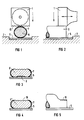
- FIG 1 und FIG 2 Ultraschallwerkzeuge zum Aufschweißen von Drähten auf metallische Träger in Vorder- und Seitenansicht,
- FIG 3 im Querschnitt einen unzulänglich aufgeschweißten Draht mit Isolierung,
- FIG 4 und FIG 5 einen erfindungsgemäß angeschweißten Draht im Querschnitt und Längsdarstellung,
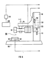
- FIG 6 eine dabei verwendete Schweißpresse mit programmierbarem Motorantrieb sowie die
- FIG 7, FIG 8 und FIG 9 Schweißgrößen-Zeit-Diagramme beim vorgeschlagenen Prozeßablauf.
- 1 and 2 show ultrasonic tools for welding wires onto metallic carriers in front and side view,
- 3 shows in cross section an inadequately welded wire with insulation,
- 4 and 5 show a wire welded according to the invention in cross-section and longitudinal representation,
- 6 shows a welding press used here with a programmable motor drive and the
- FIG 7, FIG 8 and FIG 9 weld size-time diagrams in the proposed process.
Beim Ultraschallschweißen von Drähten oder Litzen auf metallische Träger werden die Drähte oder die Litzen durch Kraftbeaufschlagung unter gleichzeitiger Ultraschalleinwirkung verformt. Insbesondere bewirken zunächst die Ultraschallschwingungen eine Beseitigung von Oberflächenverunreinigungen an den Werkstücken und speziell bei isolierten Drähten eine Entfernung der Isolierung, wonach anschließend durch den ultraschallaktivierten Reibvorgang eine stoffschlüssige Verbindung der metallischen Drähte oder Litzen mit dem Träger erreicht wird.In the case of ultrasonic welding of wires or strands onto metallic supports, the wires or the strands are deformed by the application of force with simultaneous exposure to ultrasound. In particular, the ultrasonic vibrations first remove surface contamination on the workpieces and, in particular in the case of insulated wires, remove the insulation, after which the ultrasound-activated rubbing process then achieves a cohesive connection of the metallic wires or strands to the carrier.
In FIG 1 ist für obigen Zweck eine Ultraschall-Sonotrode 1 vorhanden, die in horizontaler Richtung mit einer Frequenz von beispielsweise 20 kHz schwingt und nach einer Absenkbewegung bis auf die Werkstücke beispielsweise mit einer Kraft von beispielsweise 50 N auf die im Amboß 2 fixierten Werkstücke drückt. Letztere bestehen gemäß FIG 1 aus einem metallischen Träger 5 und einem Draht 6, beispielsweise der Dicke von 100 µm, der mit einer Isolationsschicht 7 umgeben ist. Die Sonotrode 1 kann an ihrer Arbeitsfläche eine Struktur 10, insbesondere nach Art eines sogenannten Waffelmusters, haben.1 shows an ultrasonic sonotrode 1 for the above purpose, which vibrates in the horizontal direction at a frequency of 20 kHz, for example, and after a lowering movement presses down on the workpieces, for example with a force of 50 N, for example, on the workpieces fixed in the anvil 2 . According to FIG. 1, the latter consist of a
Da bei dünner werdenden Drähten das Verhältnis von Drahtdurchmesser zur Beschichtungsstärke immer ungünstiger und damit die zu verformenden Volumina immer geringer werden, bekommt der korrekte Prozeßablauf zunehmende Bedeutung. Wird beispielsweise der Draht bei erfolgter Ultraschalleinwirkung zu schnell verformt, kann ein Querschnitt gemäß FIG 3 entstehen: Die untere Fügefläche ist hier vor der eigentlichen Verschweißung nicht hinreichend vom Kunststoff befreit. Dieser sammelt sich im Mittenbereich an, wonach das Verschweißen der metallischen Fügeflächen nur seitlich davon erfolgt. Eine solche Schweißverbindung hat weder eine hinreichende mechanische Festigkeit, noch speziell bei elektrischen Leitungen den geforderten niedrigen Übergangswiderstand.As the ratio of wire diameter to coating thickness becomes increasingly unfavorable as the wires become thinner and the volumes to be deformed become ever smaller, the correct process sequence becomes increasingly important. If, for example, the wire is deformed too quickly when the ultrasound is applied, a cross section according to FIG. 3 can arise: the lower joining surface is not sufficiently freed from the plastic before the actual welding. This accumulates in the middle area, after which the metal joining surfaces are only welded to the side of it. Such a welded connection has neither a sufficient mechanical strength, nor, especially in the case of electrical lines, the required low contact resistance.
In FIG 4 und FIG 5 ist ein auf eine Unterlage 5 korrekt angeschweißter Draht 6 dargestellt. Zum Erreichen einer solchen stoffschlüssigen Verbindung beginnt nach dem Aufsetzen der Sonotrode 1 mit Arbeitsfläche 10 auf die Beschichtung 7 des Drahtes 6 ein spezifischer Prozeßverlauf, der anhand der FIG 7 bis 9 weiter unten im einzelnen erläutert wird. Ergebnis der Schweißung ist eine gleichmäßige stoffschlüssige Verbindung des Drahtes 6 mit dem Träger 5, bei dem das Isolationsmaterial nach außen weggedrückt ist und eine Verschweißung der metallischen Materialien an ihrer gesamten Berührungsfläche erfolgt ist. Die Oberfläche hat nach Fertigstellung der Schweißverbindung eine Struktur 16 entsprechend der Struktur 10 der Sonotrode 1.4 and 5 show a
Durch ein geeignetes Antriebssystem der Schweißpresse mit Sonotrode 1 sind über einen elektrisch programmierbaren Motorantrieb die Absenkgeschwindigkeit mit ihren separaten Teilgrößen "Zustellbewegung" und "Arbeitsgeschwindigkeit" steuer- bzw. regelbar. Über ein Wegmeßsystem wird in bekannter Weise die Verformung über die vorgegebene Schweißzeit vorgewählt. Es können Wegbegrenzungen für eine konstante Restdicke des Drahtes 6 vorgegeben sein. Insbesondere wird nunmehr die Absenkgeschwindigkeit der Sonotrode 1 gezielt vorgegeben bzw. als Profil gesteuert. Damit kann die Prozeßzeit und die Qualität der Schweißverbindung optimiert werden.By means of a suitable drive system of the welding press with sonotrode 1, the lowering speed with its separate partial quantities "feed movement" and "working speed" can be controlled or regulated via an electrically programmable motor drive. The deformation over the predetermined welding time is preselected in a known manner via a displacement measuring system. There can be path limits for a constant Remaining thickness of the
Bei einer Schweißpresse 100 gemäß FIG 6 ist eine Ultraschall-Sonotrode 101 als aktives Schweißwerkzeug am verschiebbaren Schlitten 115 eines Ständers 110 angebracht. Der Ständer 110 steht auf einer Grundplatte 105 mit einem Amboß 102 als Aufnahmewerkzeug für die Fügeteile. Im Ständer 110 ist ein Drehstrommotor 120 mit Getriebe 121 angeordnet, mit dem die Motorbewegung auf den Schlitten 115 übertragen wird. Die Drehbewegung des Motors 120 bzw. die dadurch erzielte Absenkbewegung der Sonotrode 101 kann mit einem Tachogenerator 125 vorgegeben werden.In a
Der Sonotrode 101 mit Ultraschall-Wandler ist ein Generator 130 mit nachgeschaltetem Steuergerät 135 zugeordnet, mit dem gleichermaßen die Ultraschallaktivierung der Sonotrode und der Motorantrieb gesteuert wird.The
Die Schweißpresse 100 kann weiterhin einen Kraftaufnehmer 140 aufweisen, der vorteilhafterweise im Amboß 102 angeordnet ist. Gegebenenfalls kann damit die sich in den Fügeteilen aufbauende Kraft erfaßt werden. Zusätzlich kann auch ein Wegmeßsystem 150 vorhanden sein, mit dem der tatsächliche Verformungsweg der Fügeteile ermittelt wird.The
Über eine Programmierung des Steuergerätes 135 können die Ultraschallaktivierung und die Absenkgeschwindigkeit der Sonotrode 101 hinsichtlich Beginn und Ende eingestellt werden. Insbesondere die Absenkgeschwindigkeit der Sonotrode kann dabei auch als veränderliches Zeitprofil vorgegeben werden. Dieses Zeitprofil wird so eingestellt, daß ein ge wünschter Kraftverlauf realisiert wird. Dazu wird die Absenkgeschwindigkeit der Sonotrode beginnend mit der Berührung der Werkstücke zunächst klein gehalten und erst bei Plastifizierung der Werkstücke erhöht.By programming the
In FIG 7 bis FIG 9 sind die Prozeßparameter Ultraschall und Geschwindigkeit beim erfindungsgemäßen Verfahren mit elektrisch gesteuertem Pressenantrieb als Funktion der Zeit dargestellt. Der Graph 200 kennzeichnet die Absenkgeschwindigkeit der Sonotrode über einen kompletten Schweißzyklus, der sich in einzelne signifikante Bereiche einteilen läßt.7 to 9 show the process parameters ultrasound and speed in the method according to the invention with an electrically controlled press drive as a function of time. The
Im Bereich 11 verläuft die Bewegung der Sonotrode 101 mit einer freien Geschwindigkeit von beispielsweise 50 mm/s. Vom Punkt A ab wird die Absenkgeschwindigkeit wesentlich gedämpft und läuft im Bereich 12 mit geringer Geschwindigkeit. Am Punkt B wird der Ultraschall aktiviert, so daß beim Punkt C mit dem Auftreffen der Sonotrode auf die Oberfläche des Drahtes ein Kraftanstieg erfolgt, da die Werkstücke noch kalt sind.In area 11, the movement of the sonotrode 101 runs at a free speed of, for example, 50 mm / s. From point A onwards, the lowering speed is significantly damped and runs at a low speed in area 12. The ultrasound is activated at point B, so that at point C, when the sonotrode hits the surface of the wire, an increase in force occurs because the workpieces are still cold.
Gemäß FIG 7 wird in verschiedenen Varianten die Absenkgeschwindigkeit der Sonotrode entsprechend den Linien 201 bis 204 konstant vorgewählt. Dabei wird der Wert der Geschwindigkeit in Abhängigkeit von den Abmessungen und/oder der Oberflächenbeschaffenheit der Werkstücke bestimmt. Insbesondere kann somit auch einer Beschichtung der Werkstücke Rechnung getragen werden.According to FIG. 7, the lowering speed of the sonotrode is constantly preselected in accordance with
Ein Kupferdraht mit einem Durchmesser <100 µm wird beispielsweise mit der geringsten Absenkgeschwindigkeit 201 der Sonotrode 101 verschweißt werden. Für dickere Drähte, bei denen das Verformungsvolumen zunimmt, kann die Absenkgeschwindigkeit erhöht werden, was aufgrund des Motorantriebs für die Schweißpresse in einfacher Weise möglich ist.A copper wire with a diameter of <100 μm will be welded to the
In FIG 8 wird die Absenkgeschwindigkeit der Sonotrode 101 gemäß der Linie 205 zunächst für einen längeren Zeitraum bei aktivierter Sonotrode gering gewählt. Damit ist Zeit vorgegeben, die die Drahtoberfläche vom Lack zu befreien bzw. auch Oxide und andere Verunreinigungen zu entfernen. Erst nach dem an der Fügefläche sämtliche nichtmetallischen Bestandteile entfernt sind, wird die Arbeitsgeschwindigkeit stufenweise erhöht und nunmehr ein vorgegebenes Verformungsprogramm durchfahren. Dabei verändert sich der Querschnitt des Drahtes in erwünschter Weise und durch den Ultraschall aktivierten Reibvorgang der Fügeteile entsteht die Schweißverbindung gemäß den Figuren 4 und 5. Nach Abschalten des Ultraschalls wird dann die Sonotrode 101 zurückgefahren.In FIG. 8, the lowering speed of the
Eine Veränderung der Absenkgeschwindigkeit von niedrigen zu höheren Werten kann statt stufenweise auch kontinuierlich erfolgen. In FIG 9 wird die Absenkgeschwindigkeit der Sonotrode gemäß der Linie 206 nach Art eines e-Profils verändert. Auch andere funktionale Abhängigkeiten sind möglich.A change in the lowering speed from low to higher values can take place continuously instead of gradually. In FIG. 9, the lowering speed of the sonotrode is changed along the
Es hat sich gezeigt, daß beim erfindungsgemäßen Verfahren die Prozeßzeit insgesamt verringert wird. Es braucht nicht mit separatem Vorimpuls und Hauptimpuls der Ultraschalleinwirkung gearbeitet zu werden, sondern lediglich mit einer durchgehenden Ultraschallaktivierung. Als Prozeßvariable wird im wesentlichen nur die Absenkgeschwindigkeit der Sonotrode verändert, wobei die über die Schweißzeit erfolgte Verformung vorgegeben werden kann.It has been shown that the process time is reduced overall in the method according to the invention. It is not necessary to work with a separate pre-pulse and main pulse of the ultrasound effect, but only with a continuous ultrasound activation. As a process variable, essentially only the lowering speed of the sonotrode is changed, and the deformation that takes place over the welding time can be specified.
Claims (10)
Priority Applications (2)
| Application Number | Priority Date | Filing Date | Title |
|---|---|---|---|
| EP19890118618 EP0421018B1 (en) | 1989-10-06 | 1989-10-06 | Method and device for welding of metallic work-pieces with ultrasonic waves |
| DE89118618T DE58907246D1 (en) | 1989-10-06 | 1989-10-06 | Method and device for welding metallic workpieces by ultrasound. |
Applications Claiming Priority (1)
| Application Number | Priority Date | Filing Date | Title |
|---|---|---|---|
| EP19890118618 EP0421018B1 (en) | 1989-10-06 | 1989-10-06 | Method and device for welding of metallic work-pieces with ultrasonic waves |
Publications (2)
| Publication Number | Publication Date |
|---|---|
| EP0421018A1 true EP0421018A1 (en) | 1991-04-10 |
| EP0421018B1 EP0421018B1 (en) | 1994-03-16 |
Family
ID=8201990
Family Applications (1)
| Application Number | Title | Priority Date | Filing Date |
|---|---|---|---|
| EP19890118618 Expired - Lifetime EP0421018B1 (en) | 1989-10-06 | 1989-10-06 | Method and device for welding of metallic work-pieces with ultrasonic waves |
Country Status (2)
| Country | Link |
|---|---|
| EP (1) | EP0421018B1 (en) |
| DE (1) | DE58907246D1 (en) |
Cited By (12)
| Publication number | Priority date | Publication date | Assignee | Title |
|---|---|---|---|---|
| EP0701876A1 (en) * | 1994-08-22 | 1996-03-20 | SCHUNK Ultraschalltechnik GmbH | Method for compacting and welding electrical wires |
| WO1997028922A1 (en) * | 1996-02-12 | 1997-08-14 | Daimler-Benz Aktiengesellschaft | Method of bonding insulating wire and device for carrying out this method |
| EP0773600A3 (en) * | 1995-11-10 | 1998-01-14 | E.G.O. ELEKTRO-GERÄTEBAU GmbH | Electrical circuit |
| EP1060825A1 (en) * | 1999-06-16 | 2000-12-20 | Ultex Corporation | Ultrasonic vibration bonding machine |
| WO2004096480A1 (en) * | 2003-04-30 | 2004-11-11 | Schunk Ultraschalltechnik Gmbh | Method for welding parts |
| US20110259941A1 (en) * | 2010-04-27 | 2011-10-27 | Kim Soo Seong | Apparatus for monitoring bonding surface bouncing, wire bonding apparatus having the same and method for monitoring bonding surface bouncing |
| US8720516B2 (en) | 2006-05-08 | 2014-05-13 | Dukane Corporation | Ultrasonic press using servo motor with delayed motion |
| US8721817B2 (en) | 2010-07-14 | 2014-05-13 | Dukane Corporation | Vibration welding system |
| WO2014161823A1 (en) * | 2013-04-04 | 2014-10-09 | Telsonic Holding Ag | Method for connecting a tubular cable lug to a strand produced from aluminium |
| DE102013106349A1 (en) * | 2013-05-13 | 2014-11-13 | Schunk Sonosystems Gmbh | Method for determining the degree of compaction of a node |
| US9144937B2 (en) | 2006-05-08 | 2015-09-29 | Dukane Corporation | Ultrasonic press using servo motor with delayed motion |
| US10549481B1 (en) | 2018-12-21 | 2020-02-04 | Dukane Ias, Llc | Systems and methods for low initial weld speed in ultrasonic welding |
Families Citing this family (2)
| Publication number | Priority date | Publication date | Assignee | Title |
|---|---|---|---|---|
| US9688017B2 (en) | 2013-05-14 | 2017-06-27 | Dukan IAS, LLC | Vibration welders with high frequency vibration, position motion control, and delayed weld motion |
| DE102022128873A1 (en) | 2022-11-01 | 2024-05-02 | Albert-Ludwigs-Universität Freiburg, Körperschaft des öffentlichen Rechts | Ultrasonic welding process with joining partner feedback and device for this |
Citations (2)
| Publication number | Priority date | Publication date | Assignee | Title |
|---|---|---|---|---|
| FR2302172A1 (en) * | 1975-02-27 | 1976-09-24 | Podselver Michel | Ultrasonic welding appts. using electronic comparator circuit - with logic elements, for precise control of welding pressure and time |
| US4631685A (en) * | 1984-12-07 | 1986-12-23 | General Motors Corporation | Method and apparatus for ultrasonic plastic forming and joining |
-
1989
- 1989-10-06 DE DE89118618T patent/DE58907246D1/en not_active Expired - Fee Related
- 1989-10-06 EP EP19890118618 patent/EP0421018B1/en not_active Expired - Lifetime
Patent Citations (2)
| Publication number | Priority date | Publication date | Assignee | Title |
|---|---|---|---|---|
| FR2302172A1 (en) * | 1975-02-27 | 1976-09-24 | Podselver Michel | Ultrasonic welding appts. using electronic comparator circuit - with logic elements, for precise control of welding pressure and time |
| US4631685A (en) * | 1984-12-07 | 1986-12-23 | General Motors Corporation | Method and apparatus for ultrasonic plastic forming and joining |
Non-Patent Citations (1)
| Title |
|---|
| WELDING JOURNAL vol. 57, no. 2, Februar 1978, Miami,FL,US Seiten 19 - 25; HULST: "Ultrasonic bonding of insulated wire" * |
Cited By (18)
| Publication number | Priority date | Publication date | Assignee | Title |
|---|---|---|---|---|
| EP0701876A1 (en) * | 1994-08-22 | 1996-03-20 | SCHUNK Ultraschalltechnik GmbH | Method for compacting and welding electrical wires |
| EP0773600A3 (en) * | 1995-11-10 | 1998-01-14 | E.G.O. ELEKTRO-GERÄTEBAU GmbH | Electrical circuit |
| WO1997028922A1 (en) * | 1996-02-12 | 1997-08-14 | Daimler-Benz Aktiengesellschaft | Method of bonding insulating wire and device for carrying out this method |
| US6100511A (en) * | 1996-02-12 | 2000-08-08 | Daimler-Benz Aktiengesellschaft | Method of bonding insulating wire and device for carrying out this method |
| EP1060825A1 (en) * | 1999-06-16 | 2000-12-20 | Ultex Corporation | Ultrasonic vibration bonding machine |
| US6491785B1 (en) | 1999-06-16 | 2002-12-10 | Ultex Corporation | Ultrasonic vibration bonding machine |
| WO2004096480A1 (en) * | 2003-04-30 | 2004-11-11 | Schunk Ultraschalltechnik Gmbh | Method for welding parts |
| US9144937B2 (en) | 2006-05-08 | 2015-09-29 | Dukane Corporation | Ultrasonic press using servo motor with delayed motion |
| US9586361B2 (en) | 2006-05-08 | 2017-03-07 | Dukane Ias, Llc | Ultrasonic press using servo motor with delayed motion |
| US8720516B2 (en) | 2006-05-08 | 2014-05-13 | Dukane Corporation | Ultrasonic press using servo motor with delayed motion |
| US9486955B2 (en) | 2006-05-08 | 2016-11-08 | Dukane Ias, Llc | Ultrasonic press using servo motor with delayed motion |
| CN102237263A (en) * | 2010-04-27 | 2011-11-09 | 三星Led株式会社 | Apparatus and method for monitoring bonding surface bouncing, wire bonding apparatus and recording medium |
| US20110259941A1 (en) * | 2010-04-27 | 2011-10-27 | Kim Soo Seong | Apparatus for monitoring bonding surface bouncing, wire bonding apparatus having the same and method for monitoring bonding surface bouncing |
| US8721817B2 (en) | 2010-07-14 | 2014-05-13 | Dukane Corporation | Vibration welding system |
| WO2014161823A1 (en) * | 2013-04-04 | 2014-10-09 | Telsonic Holding Ag | Method for connecting a tubular cable lug to a strand produced from aluminium |
| US9855623B2 (en) | 2013-04-04 | 2018-01-02 | Telsonic Holding Ag | Method for connecting a tubular cable lug to a strand produced from aluminium |
| DE102013106349A1 (en) * | 2013-05-13 | 2014-11-13 | Schunk Sonosystems Gmbh | Method for determining the degree of compaction of a node |
| US10549481B1 (en) | 2018-12-21 | 2020-02-04 | Dukane Ias, Llc | Systems and methods for low initial weld speed in ultrasonic welding |
Also Published As
| Publication number | Publication date |
|---|---|
| DE58907246D1 (en) | 1994-04-21 |
| EP0421018B1 (en) | 1994-03-16 |
Similar Documents
| Publication | Publication Date | Title |
|---|---|---|
| EP0421019B1 (en) | Method and device for joining plastic parts with ultrasonic waves | |
| EP0421018B1 (en) | Method and device for welding of metallic work-pieces with ultrasonic waves | |
| EP2289659B1 (en) | Apparatus for frictionally connecting at least two plates through a connecting element with a system for measuring the applied load and the advancing length during connection | |
| DE60206893T2 (en) | TURNING FRICTION WELDING PROCESS AND DEVICE | |
| EP3119584B1 (en) | Device and method for setting a setting element in a component | |
| DE60312793T2 (en) | Method and use of a device for friction stir welding | |
| EP0340671B1 (en) | Process and apparatus for controlling the machine parameters in friction welding | |
| DE3037505C2 (en) | ||
| DE19523240C1 (en) | Method and device for friction welding workpieces | |
| EP0759332B1 (en) | CNC-controlled tube bending machine | |
| DE102004034498A1 (en) | Method for friction welding of components | |
| WO2000064620A1 (en) | Welding method and welding device for carrying out said welding method | |
| EP0776261B2 (en) | Device for welding together at least two parts, and method using the device | |
| DE102009009178A1 (en) | Device for machining saw teeth of a saw blade | |
| EP3847707A1 (en) | Method for electrically contacting a battery block | |
| DE3226362C2 (en) | Method for braking friction welding machines when friction welding parts with a precise angular position after welding | |
| DE278185T1 (en) | NUMERICALLY CONTROLLED RESISTANCE WELDING MACHINE AND BOLT AND NUT SYSTEM OR ANALOG | |
| DE102011104840A1 (en) | Method for performing ultrasonic punching of workpiece e.g. plastic bumper, involves inserting workpiece into opening formed in workpiece supporting unit, by using punching tool with usage of ultrasound | |
| EP0687519B1 (en) | Process and device for welding tinned sheet metal elements by means of laser beams | |
| DE2248471A1 (en) | Plastics deformed esp. to form rivet head or flange - using only frictional heat of rotating die to soften plastics | |
| EP3546084B1 (en) | Method for connecting at least two workpieces by means of a punch rivet device and punch rivet device | |
| DE19708247B4 (en) | Apparatus and method for bending a workpiece | |
| EP4065349B1 (en) | Ultrasonic treatment method | |
| AT503471B1 (en) | METHOD AND DEVICE FOR CONNECTING METALLIC ELEMENTS TO THE FRICTION WELDING METHOD | |
| DE102004004194A1 (en) | Boring equipment for producing holes in thin-walled, large area, rigid three dimensional plastic parts has cutting and embossing tools and cutting unit performs feeding and rotating movements |
Legal Events
| Date | Code | Title | Description |
|---|---|---|---|
| PUAI | Public reference made under article 153(3) epc to a published international application that has entered the european phase |
Free format text: ORIGINAL CODE: 0009012 |
|
| 17P | Request for examination filed |
Effective date: 19901009 |
|
| AK | Designated contracting states |
Kind code of ref document: A1 Designated state(s): CH DE FR GB LI NL |
|
| 17Q | First examination report despatched |
Effective date: 19920131 |
|
| GRAA | (expected) grant |
Free format text: ORIGINAL CODE: 0009210 |
|
| AK | Designated contracting states |
Kind code of ref document: B1 Designated state(s): CH DE FR GB LI NL |
|
| REF | Corresponds to: |
Ref document number: 58907246 Country of ref document: DE Date of ref document: 19940421 |
|
| GBT | Gb: translation of ep patent filed (gb section 77(6)(a)/1977) |
Effective date: 19940624 |
|
| ET | Fr: translation filed | ||
| PLBE | No opposition filed within time limit |
Free format text: ORIGINAL CODE: 0009261 |
|
| STAA | Information on the status of an ep patent application or granted ep patent |
Free format text: STATUS: NO OPPOSITION FILED WITHIN TIME LIMIT |
|
| 26N | No opposition filed | ||
| REG | Reference to a national code |
Ref country code: GB Ref legal event code: 732E |
|
| NLS | Nl: assignments of ep-patents |
Owner name: HELMUT MOLL |
|
| PGFP | Annual fee paid to national office [announced via postgrant information from national office to epo] |
Ref country code: GB Payment date: 19981023 Year of fee payment: 10 |
|
| PGFP | Annual fee paid to national office [announced via postgrant information from national office to epo] |
Ref country code: NL Payment date: 19981030 Year of fee payment: 10 |
|
| PGFP | Annual fee paid to national office [announced via postgrant information from national office to epo] |
Ref country code: FR Payment date: 19981116 Year of fee payment: 10 |
|
| REG | Reference to a national code |
Ref country code: FR Ref legal event code: TP |
|
| PGFP | Annual fee paid to national office [announced via postgrant information from national office to epo] |
Ref country code: DE Payment date: 19981130 Year of fee payment: 10 |
|
| PGFP | Annual fee paid to national office [announced via postgrant information from national office to epo] |
Ref country code: CH Payment date: 19981210 Year of fee payment: 10 |
|
| REG | Reference to a national code |
Ref country code: CH Ref legal event code: PUE Owner name: SIEMENS AKTIENGESELLSCHAFT TRANSFER- HELMUT MOLL Ref country code: CH Ref legal event code: NV Representative=s name: ISLER & PEDRAZZINI AG |
|
| PG25 | Lapsed in a contracting state [announced via postgrant information from national office to epo] |
Ref country code: GB Free format text: LAPSE BECAUSE OF NON-PAYMENT OF DUE FEES Effective date: 19991006 |
|
| PG25 | Lapsed in a contracting state [announced via postgrant information from national office to epo] |
Ref country code: LI Free format text: LAPSE BECAUSE OF NON-PAYMENT OF DUE FEES Effective date: 19991031 Ref country code: CH Free format text: LAPSE BECAUSE OF NON-PAYMENT OF DUE FEES Effective date: 19991031 |
|
| PG25 | Lapsed in a contracting state [announced via postgrant information from national office to epo] |
Ref country code: NL Free format text: LAPSE BECAUSE OF NON-PAYMENT OF DUE FEES Effective date: 20000501 |
|
| GBPC | Gb: european patent ceased through non-payment of renewal fee |
Effective date: 19991006 |
|
| REG | Reference to a national code |
Ref country code: CH Ref legal event code: PL |
|
| PG25 | Lapsed in a contracting state [announced via postgrant information from national office to epo] |
Ref country code: FR Free format text: LAPSE BECAUSE OF NON-PAYMENT OF DUE FEES Effective date: 20000630 |
|
| NLV4 | Nl: lapsed or anulled due to non-payment of the annual fee |
Effective date: 20000501 |
|
| PG25 | Lapsed in a contracting state [announced via postgrant information from national office to epo] |
Ref country code: DE Free format text: LAPSE BECAUSE OF NON-PAYMENT OF DUE FEES Effective date: 20000801 |
|
| REG | Reference to a national code |
Ref country code: FR Ref legal event code: ST |