EP0420797A2 - Abutment piece for concrete forms - Google Patents
Abutment piece for concrete forms Download PDFInfo
- Publication number
- EP0420797A2 EP0420797A2 EP90810670A EP90810670A EP0420797A2 EP 0420797 A2 EP0420797 A2 EP 0420797A2 EP 90810670 A EP90810670 A EP 90810670A EP 90810670 A EP90810670 A EP 90810670A EP 0420797 A2 EP0420797 A2 EP 0420797A2
- Authority
- EP
- European Patent Office
- Prior art keywords
- stop body
- nail
- sleeve
- abutment
- abutment piece
- Prior art date
- Legal status (The legal status is an assumption and is not a legal conclusion. Google has not performed a legal analysis and makes no representation as to the accuracy of the status listed.)
- Granted
Links
- 238000009415 formwork Methods 0.000 claims description 5
- 239000006096 absorbing agent Substances 0.000 description 1
- 238000004873 anchoring Methods 0.000 description 1
- 230000006835 compression Effects 0.000 description 1
- 238000007906 compression Methods 0.000 description 1
- 238000003780 insertion Methods 0.000 description 1
- 230000037431 insertion Effects 0.000 description 1
- 239000000463 material Substances 0.000 description 1
- 238000000034 method Methods 0.000 description 1
- 230000035939 shock Effects 0.000 description 1
Images
Classifications
-
- E—FIXED CONSTRUCTIONS
- E04—BUILDING
- E04G—SCAFFOLDING; FORMS; SHUTTERING; BUILDING IMPLEMENTS OR AIDS, OR THEIR USE; HANDLING BUILDING MATERIALS ON THE SITE; REPAIRING, BREAKING-UP OR OTHER WORK ON EXISTING BUILDINGS
- E04G17/00—Connecting or other auxiliary members for forms, falsework structures, or shutterings
- E04G17/06—Tying means; Spacers ; Devices for extracting or inserting wall ties
- E04G17/064—Spacers placed on the bottom of the mould
-
- E—FIXED CONSTRUCTIONS
- E04—BUILDING
- E04G—SCAFFOLDING; FORMS; SHUTTERING; BUILDING IMPLEMENTS OR AIDS, OR THEIR USE; HANDLING BUILDING MATERIALS ON THE SITE; REPAIRING, BREAKING-UP OR OTHER WORK ON EXISTING BUILDINGS
- E04G17/00—Connecting or other auxiliary members for forms, falsework structures, or shutterings
- E04G17/14—Bracing or strutting arrangements for formwalls; Devices for aligning forms
-
- F—MECHANICAL ENGINEERING; LIGHTING; HEATING; WEAPONS; BLASTING
- F16—ENGINEERING ELEMENTS AND UNITS; GENERAL MEASURES FOR PRODUCING AND MAINTAINING EFFECTIVE FUNCTIONING OF MACHINES OR INSTALLATIONS; THERMAL INSULATION IN GENERAL
- F16B—DEVICES FOR FASTENING OR SECURING CONSTRUCTIONAL ELEMENTS OR MACHINE PARTS TOGETHER, e.g. NAILS, BOLTS, CIRCLIPS, CLAMPS, CLIPS OR WEDGES; JOINTS OR JOINTING
- F16B19/00—Bolts without screw-thread; Pins, including deformable elements; Rivets
- F16B19/14—Bolts or the like for shooting into concrete constructions, metal walls or the like by means of detonation-operated nailing tools
-
- F—MECHANICAL ENGINEERING; LIGHTING; HEATING; WEAPONS; BLASTING
- F16—ENGINEERING ELEMENTS AND UNITS; GENERAL MEASURES FOR PRODUCING AND MAINTAINING EFFECTIVE FUNCTIONING OF MACHINES OR INSTALLATIONS; THERMAL INSULATION IN GENERAL
- F16B—DEVICES FOR FASTENING OR SECURING CONSTRUCTIONAL ELEMENTS OR MACHINE PARTS TOGETHER, e.g. NAILS, BOLTS, CIRCLIPS, CLAMPS, CLIPS OR WEDGES; JOINTS OR JOINTING
- F16B43/00—Washers or equivalent devices; Other devices for supporting bolt-heads or nuts
-
- Y—GENERAL TAGGING OF NEW TECHNOLOGICAL DEVELOPMENTS; GENERAL TAGGING OF CROSS-SECTIONAL TECHNOLOGIES SPANNING OVER SEVERAL SECTIONS OF THE IPC; TECHNICAL SUBJECTS COVERED BY FORMER USPC CROSS-REFERENCE ART COLLECTIONS [XRACs] AND DIGESTS
- Y10—TECHNICAL SUBJECTS COVERED BY FORMER USPC
- Y10S—TECHNICAL SUBJECTS COVERED BY FORMER USPC CROSS-REFERENCE ART COLLECTIONS [XRACs] AND DIGESTS
- Y10S411/00—Expanded, threaded, driven, headed, tool-deformed, or locked-threaded fastener
- Y10S411/904—Fastener or fastener element composed of nonmetallic material
- Y10S411/908—Resinous material
Definitions
- the invention relates to a stop body for concrete formwork, with a passage opening and abutment for a nail, a crumple zone being provided between the abutment and the stop body.
- a stop body which is provided for the lateral support of concrete formwork and is attached to a component by means of a nail.
- a passage opening and an abutment are provided for the nail, a crumple zone being arranged between the abutment and the stop body.
- the crumple zone acts as a shock absorber and prevents damage to the stop body.
- the crumple zone is formed by a ring that is slidably seated on the nail, the end of which serves as an abutment.
- the nail must be fitted with the ring before insertion into the passage opening of the stop body, which proves to be cumbersome. There is also a risk of forgetting to apply the ring to the nail.
- a disadvantage of the known arrangement is above all that the ring tears open radially during the compression and falls off the shaft of the nail. As a result, the support of the stop body by the nail is lost.
- the invention has for its object to provide a stop body with abutment and crumple zone, which ensures easy handling and safe function.
- the object is achieved in that the crumple zone is designed as a compressible part which is integrally connected to the stop body.
- the compressible part can also with possible radial tearing do not jump off, so that the safe functioning of the stop body is guaranteed.
- the one-piece connection is preferably made in that the compressible part is molded directly onto the stop body.
- the compressible part connected to the stop body in this way is thus available such that after the stop body has been placed on the component, only the nail has to be driven into the component through the passage opening. If this is done using a powder-operated setting tool, it can be supported laterally on the muzzle side of the compressible part, which has particular advantages in terms of handling.
- the compressible part is preferably designed as a free-standing sleeve.
- the sleeve can protrude from a support surface of the stop body facing the abutment. In the event of excess energy, the forces introduced by the nail onto the abutment are introduced directly into the component via the stop body, the sleeve being axially compressed in accordance with the excess energy.
- the free end of the sleeve is advantageously set back axially with respect to the outer contour of the stop body. This ensures that the driven nail does not project axially beyond the stop body. In this way it is avoided that the concrete formwork at most strikes the nail when approaching the stop body, which could lead to a load impairing the anchoring of the nail.
- the stop body 1 is made of plastic and is integrally connected to a sleeve 2 serving as a crumple zone.
- a stop opening 3 passes through the stop body 1 and the sleeve 2.
- the sleeve 2 sits on a hub-like inner part 4 of the stop body 1, which is connected by a base part 5 to an essentially hollow cylindrical jacket part 6.
- ribs 7 are provided between the base part 5 and the jacket part 6, as illustrated in FIG. 2.
- the free-standing end of the sleeve 2 serves as an abutment 8 and is set back by approximately the diameter of the sleeve 2 relative to the outer contour of the jacket part 6.
- the other end face of the jacket part 6 has a plurality of support fingers 9 distributed over the circumference.
- a stop body 1 is fastened to a component 11, for example made of concrete, in order to laterally support a concrete formwork 12.
- the support fingers 9 ensure stable support of the stop body 1 even in the event of any unevenness in the top of the component 11.
- a nail 13 has been driven into the component 11 through the passage opening 3.
- the driving in of the nail 13, which is preferably carried out with the aid of a powder-operated setting tool, can, depending on the strength of the component 11 in the area of the driving-in point, lead from fastening point to fastening point to driving the nail 13 to different depths.
- the head 13a of the nail 13 running towards the end of the driving-in process on the abutment 8 displaces the abutment 8 in the driving-in direction, the sleeve 2, as shown in FIG. 3, is axially compressed.
- the head 13a remains in contact with the abutment 8, so that the stop body 1 is held against the component 11 via the compressed sleeve 2 connected to the inner part 4.
- the upsetting of the sleeve 2 also contributes to the reduction of the excess energy imparted to the nail 13.
Landscapes
- Engineering & Computer Science (AREA)
- General Engineering & Computer Science (AREA)
- Mechanical Engineering (AREA)
- Architecture (AREA)
- Civil Engineering (AREA)
- Structural Engineering (AREA)
- Forms Removed On Construction Sites Or Auxiliary Members Thereof (AREA)
- Organic Low-Molecular-Weight Compounds And Preparation Thereof (AREA)
- Portable Nailing Machines And Staplers (AREA)
Abstract
Description
Die Erfindung betrifft einen Anschlagkörper für Betonschalungen, mit Durchtrittsöffnung und Widerlager für einen Nagel, wobei zwischen Widerlager und Anschlagkörper eine Knautschzone vorgesehen ist.The invention relates to a stop body for concrete formwork, with a passage opening and abutment for a nail, a crumple zone being provided between the abutment and the stop body.
Aus der DE-A 30 009 672 ist ein Anschlagkörper bekannt, der zur seitlichen Abstützung von Betonschalungen vorgesehen ist und mittels eines Nagels an einem Bauteil befestigt wird. Für den Nagel ist eine Durchtrittsöffnung und ein Widerlager vorgesehen, wobei zwischen Widerlager und Anschlagkörper eine Knautschzone angeordnet ist. Die Knautschzone wirkt als Stossdämpfer und verhindert Beschädigungen des Anschlagkörpers.From DE-A 30 009 672 a stop body is known, which is provided for the lateral support of concrete formwork and is attached to a component by means of a nail. A passage opening and an abutment are provided for the nail, a crumple zone being arranged between the abutment and the stop body. The crumple zone acts as a shock absorber and prevents damage to the stop body.
Die Knautschzone ist von einem verschiebbar auf dem Nagel sitzenden Ring gebildet, dessen Stirnseite als Widerlager dient. Der Nagel ist vor dem Einführen in die Durchtrittsöffnung des Anschlagkörpers mit dem Ring zu bestücken, was sich als umständlich erweist. Dabei besteht auch die Gefahr, dass vergessen wird, den Ring auf den Nagel aufzubringen. Ein Nachteil der bekannten Anordnung besteht vor allem auch darin, dass der Ring bei der Stauchung radial aufreisst und vom Schaft des Nagels abfällt. Dadurch geht die Abstützung des Anschlagkörpers durch den Nagel verloren.The crumple zone is formed by a ring that is slidably seated on the nail, the end of which serves as an abutment. The nail must be fitted with the ring before insertion into the passage opening of the stop body, which proves to be cumbersome. There is also a risk of forgetting to apply the ring to the nail. A disadvantage of the known arrangement is above all that the ring tears open radially during the compression and falls off the shaft of the nail. As a result, the support of the stop body by the nail is lost.
Der Erfindung liegt die Aufgabe zugrunde, einen Anschlagkörper mit Widerlager und Knautschzone zu schaffen, der eine einfache Handhabung und eine sichere Funktion gewährleistet.The invention has for its object to provide a stop body with abutment and crumple zone, which ensures easy handling and safe function.
Erfindungsgemäss wird die Aufgabe dadurch gelöst, dass die Knautschzone als mit dem Anschlagkörper einstückig verbundenes, stauchbares Teil ausgebildet ist.According to the invention, the object is achieved in that the crumple zone is designed as a compressible part which is integrally connected to the stop body.
Durch die einstückige Verbindung mit dem Anschlagkörper kann das stauchbare Teil auch bei allfälligem radialem Reissen nicht abspringen, so dass die sichere Funktion des Anschlagkörpers gewährleistet ist.Due to the one-piece connection with the stop body, the compressible part can also with possible radial tearing do not jump off, so that the safe functioning of the stop body is guaranteed.
Bei Verwendung von Kunststoff als Material für den Anschlagkörper erfolgt die einstückige Verbindung vorzugsweise dadurch, dass das stauchbare Teil unmittelbar am Anschlagkörper angespritzt ist. Das mit dem Anschlagkörper auf diese Weise verbundene stauchbare Teil steht somit derart zur Verfügung, dass nach dem Auflegen des Anschlagkörpers auf das Bauteil lediglich der Nagel durch die Durchtrittsöffnung hindurch in das Bauteil eingetrieben werden muss. Erfolgt dies mittels eines pulverkraftbetriebenen Setzgerätes, kann sich dieses mündungsseitig am stauchbaren Teil seitlich abstützen, was insbesondere handhabungstechnische Vorteile hat.If plastic is used as the material for the stop body, the one-piece connection is preferably made in that the compressible part is molded directly onto the stop body. The compressible part connected to the stop body in this way is thus available such that after the stop body has been placed on the component, only the nail has to be driven into the component through the passage opening. If this is done using a powder-operated setting tool, it can be supported laterally on the muzzle side of the compressible part, which has particular advantages in terms of handling.
Vorzugsweise ist das stauchbare Teil als freistehende Hülse ausgebildet. Die Hülse kann dabei von einer dem Widerlager zugewandten Stützfläche des Anschlagkörpers abragen. Bei Ueberenergie werden die vom Nagel auf das Widerlager eingeleiteten Kräfte über den Anschlagkörper direkt in das Bauteil eingeleitet, wobei die Hülse entsprechend der Ueberenergie axial gestaucht wird.The compressible part is preferably designed as a free-standing sleeve. The sleeve can protrude from a support surface of the stop body facing the abutment. In the event of excess energy, the forces introduced by the nail onto the abutment are introduced directly into the component via the stop body, the sleeve being axially compressed in accordance with the excess energy.
Mit Vorteil ist das freie Ende der Hülse gegenüber der Aussenkontur des Anschlagkörpers axial zurückversetzt. Dadurch wird sichergestellt, dass der eingetriebene Nagel den Anschlagkörper axial nicht überragt. Auf diese Weise wird vermieden, dass die Betonschalungen beim Heranführen an den Anschlagkörper allenfalls an den Nagel anschlagen, was zu einer die Verankerung des Nagels beeinträchtigenden Beanspruchung führen könnte.The free end of the sleeve is advantageously set back axially with respect to the outer contour of the stop body. This ensures that the driven nail does not project axially beyond the stop body. In this way it is avoided that the concrete formwork at most strikes the nail when approaching the stop body, which could lead to a load impairing the anchoring of the nail.
Die Erfindung wird nachstehend anhand einer Zeichnung, die ein Ausführungsbeispiel wiedergibt, näher erläutert. Es zeigen:
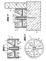
- Fig. 1 einen Anschlagkörper im Längsschnitt;
- Fig. 2 einen Grundriss des Anschlagkörpers nach Fig. 1;
- Fig. 3 einen mittels eines Nagels an einem Bauteil befestigten Anschlagkörper nach Fig. 1.
- 1 shows a stop body in longitudinal section.
- FIG. 2 shows a plan view of the stop body according to FIG. 1;
- 3 shows a stop body according to FIG. 1 fastened to a component by means of a nail.
Der Anschlagkörper 1 besteht aus Kunststoff und ist einstückig mit einer als Knautschzone dienenden Hülse 2 verbunden. Der Anschlagkörper 1 und die Hülse 2 sind von einer Durchtrittsöffnung 3 durchsetzt. Die Hülse 2 sitzt auf einem nabenartigen Innenteil 4 des Anschlagkörpers 1, das durch ein Bodenteil 5 mit einem im wesentlichen hohlzylindrischen Mantelteil 6 verbunden ist. Aus Versteifungsgründen sind zwischen dem Bodenteil 5 und dem Mantelteil 6 Rippen 7 vorgesehen, wie in der Fig. 2 verdeutlicht.The stop body 1 is made of plastic and is integrally connected to a
Das freistehende Ende der Hülse 2 dient als Widerlager 8 und ist gegenüber der stirnseitigen Aussenkontur des Mantelteiles 6 um etwa den Durchmesser der Hülse 2 zurückversetzt. Die andere Stirnseite des Mantelteiles 6 weist über den Umfang verteilt mehrere Stützfinger 9 auf.The free-standing end of the
Gemäss Fig. 3 ist ein Anschlagkörper 1 auf einem beispielsweise aus Beton bestehenden Bauteil 11 befestigt, um seitlich eine Betonschalung 12 abzustützen. Die Stützfinger 9 stellen auch bei allfälliger Unebenheit der Oberseite des Bauteiles 11 eine stabile Abstützung des Anschlagkörpers 1 sicher. Zum Befestigen des Anschlagkörpers 1 am Bauteil 11 ist ein Nagel 13 durch die Durchtrittsöffnung 3 hindurch in das Bauteil 11 eingetrieben worden. Das vorzugsweise mit Hilfe eines pulverkraftbetriebenen Setzgerätes erfolgende Eintreiben des Nagels 13 kann je nach Festigkeit des Bauteiles 11 im Bereich der Eintreibstelle von Befestigungsstelle zu Befestigungsstelle zu unterschiedlich tiefem Eintreiben des Nagels 13 führen. Je nach Eintreibtiefe verschiebt der gegen Ende des Eintreibvorganges am Widerlager 8 auflaufende Kopf 13a des Nagels 13 das Widerlager 8 in Eintreibrichtung mit, wobei die Hülse 2, wie in Fig. 3 gezeigt, axial gestaucht wird. Der Kopf 13a bleibt in Anlage am Widerlager 8, so dass über die an das Innenteil 4 angebundene gestauchte Hülse 2 der Anschlagkörper 1 gegen das Bauteil 11 gehalten wird. Das Stauchen der Hülse 2 trägt auch zum Abbau der dem Nagel 13 vermittelten Ueberenergie bei.According to FIG. 3, a stop body 1 is fastened to a
Claims (3)
Priority Applications (1)
| Application Number | Priority Date | Filing Date | Title |
|---|---|---|---|
| AT90810670T ATE98732T1 (en) | 1989-09-23 | 1990-09-05 | STOPPER FOR CONCRETE FORMWORK. |
Applications Claiming Priority (2)
| Application Number | Priority Date | Filing Date | Title |
|---|---|---|---|
| DE3931831 | 1989-09-23 | ||
| DE3931831A DE3931831A1 (en) | 1989-09-23 | 1989-09-23 | ANCHOR BODY FOR CONCRETE SHUTTERING |
Publications (3)
| Publication Number | Publication Date |
|---|---|
| EP0420797A2 true EP0420797A2 (en) | 1991-04-03 |
| EP0420797A3 EP0420797A3 (en) | 1991-08-28 |
| EP0420797B1 EP0420797B1 (en) | 1993-12-15 |
Family
ID=6390061
Family Applications (1)
| Application Number | Title | Priority Date | Filing Date |
|---|---|---|---|
| EP90810670A Expired - Lifetime EP0420797B1 (en) | 1989-09-23 | 1990-09-05 | Abutment piece for concrete forms |
Country Status (5)
| Country | Link |
|---|---|
| US (1) | US5125616A (en) |
| EP (1) | EP0420797B1 (en) |
| AT (1) | ATE98732T1 (en) |
| CA (1) | CA2025923C (en) |
| DE (2) | DE3931831A1 (en) |
Cited By (5)
| Publication number | Priority date | Publication date | Assignee | Title |
|---|---|---|---|---|
| EP0676551A2 (en) * | 1994-04-09 | 1995-10-11 | HILTI Aktiengesellschaft | Fastening element driven into hard parent materials by means of explosive-driven setting tools |
| EP0875643A1 (en) | 1997-05-03 | 1998-11-04 | HILTI Aktiengesellschaft | Concrete form aligner |
| DE29812111U1 (en) * | 1998-07-09 | 1999-11-18 | Adolf Würth GmbH & Co. KG, 74653 Künzelsau | Formwork stop |
| EP1538345A1 (en) * | 2003-12-01 | 2005-06-08 | HILTI Aktiengesellschaft | Auxiliary construction element |
| DE202009006026U1 (en) | 2009-04-22 | 2009-07-02 | Adolf Würth GmbH & Co. KG | Abutment body for concrete formwork |
Families Citing this family (14)
| Publication number | Priority date | Publication date | Assignee | Title |
|---|---|---|---|---|
| US5332191A (en) * | 1992-10-26 | 1994-07-26 | Nolan Terry L | Apparatus for making concrete slabs |
| DE4318965C2 (en) * | 1993-06-08 | 1996-04-11 | Hilti Ag | Fastening method |
| DE19505841A1 (en) * | 1995-02-21 | 1996-08-22 | Hilti Ag | Fastening element for attaching large thickness plates to components |
| US7004704B1 (en) * | 2004-09-30 | 2006-02-28 | Illinois Tool Works Inc. | Flute positioner |
| FR2883341B1 (en) * | 2005-03-18 | 2007-06-29 | Prospection Et D Inv S Techniq | ASSEMBLY OF A BASE AND FIXING BUFFER |
| US7654784B2 (en) * | 2006-01-31 | 2010-02-02 | Honeywell International Inc. | Device housing with integral fastener retainers |
| MXPA06003044A (en) * | 2006-03-17 | 2007-09-17 | Juan Antonio Ferro De La Cruz | Device for aligning modular centres in concrete walls, and alignment method. |
| US20080315065A1 (en) * | 2007-06-22 | 2008-12-25 | Hanson Troy A | Bracket assembly for facilitating the installation of a concrete wall on a concrete footing and a method of forming the wall |
| US8348226B2 (en) * | 2007-06-22 | 2013-01-08 | Hanson Troy A | Bracket assembly for facilitation the installation of a concrete wall on a concrete footing and a method of forming the wall |
| DE102008001170A1 (en) * | 2008-04-14 | 2009-10-15 | Hilti Aktiengesellschaft | Abutment body for concrete formwork |
| DE102009028119A1 (en) | 2009-07-30 | 2011-02-03 | Hilti Aktiengesellschaft | stop body |
| RU167465U1 (en) * | 2016-08-04 | 2017-01-10 | Дмитрий Витальевич Гвидонский | ELECTRIC INSULATION WASHER FOR RAIL FASTENING |
| US11059586B2 (en) * | 2019-05-29 | 2021-07-13 | The Boeing Company | Structural spacer members |
| USD913081S1 (en) | 2019-05-29 | 2021-03-16 | The Boeing Company | Structural spacer member |
Citations (4)
| Publication number | Priority date | Publication date | Assignee | Title |
|---|---|---|---|---|
| GB1166301A (en) * | 1966-01-12 | 1969-10-08 | Olin Mathieson | Fasteners for Use in Power-Actuated Tools. |
| FR2260018A1 (en) * | 1974-02-05 | 1975-08-29 | Olin Corp | Impact dowel and fixing braket - dowel fired from "nail gun" retains bracket against surface |
| EP0282445A1 (en) * | 1987-03-07 | 1988-09-14 | HILTI Aktiengesellschaft | Fastener with a nail and a sleeve |
| EP0321396A2 (en) * | 1987-12-18 | 1989-06-21 | HILTI Aktiengesellschaft | Mail with a compressible sleeve |
Family Cites Families (8)
| Publication number | Priority date | Publication date | Assignee | Title |
|---|---|---|---|---|
| US2092684A (en) * | 1935-01-18 | 1937-09-07 | Timber Engineering Co | Shear plate |
| US2614310A (en) * | 1948-08-21 | 1952-10-21 | James Robert Maxwell | Undercut former |
| US3469817A (en) * | 1967-10-20 | 1969-09-30 | Symons Mfg Co | Hole-pattern member for use in connection with a concrete floor slab form |
| US4077599A (en) * | 1975-02-18 | 1978-03-07 | Oland John H | Device for forming apertures in concrete |
| US4289060A (en) * | 1977-10-03 | 1981-09-15 | Hooker Chemicals & Plastics Corp. | Device and assembly for mounting parts |
| FR2451434A1 (en) * | 1979-03-15 | 1980-10-10 | Laroche Jean Pierre | Precast concrete kicker block for in-situ concrete wall - has circular shape and is nailed to base to locate feet wall forms |
| US4669169A (en) * | 1981-05-29 | 1987-06-02 | Anchor Wire Corporation Of Tennessee | Method of mounting an article to a substrate |
| GB8612003D0 (en) * | 1986-05-16 | 1986-06-25 | Dunlop Construction Products I | Attaching sheet material to substrate |
-
1989
- 1989-09-23 DE DE3931831A patent/DE3931831A1/en not_active Withdrawn
-
1990
- 1990-09-05 EP EP90810670A patent/EP0420797B1/en not_active Expired - Lifetime
- 1990-09-05 AT AT90810670T patent/ATE98732T1/en not_active IP Right Cessation
- 1990-09-05 DE DE90810670T patent/DE59003869D1/en not_active Expired - Lifetime
- 1990-09-21 CA CA002025923A patent/CA2025923C/en not_active Expired - Fee Related
- 1990-09-24 US US07/587,238 patent/US5125616A/en not_active Expired - Lifetime
Patent Citations (4)
| Publication number | Priority date | Publication date | Assignee | Title |
|---|---|---|---|---|
| GB1166301A (en) * | 1966-01-12 | 1969-10-08 | Olin Mathieson | Fasteners for Use in Power-Actuated Tools. |
| FR2260018A1 (en) * | 1974-02-05 | 1975-08-29 | Olin Corp | Impact dowel and fixing braket - dowel fired from "nail gun" retains bracket against surface |
| EP0282445A1 (en) * | 1987-03-07 | 1988-09-14 | HILTI Aktiengesellschaft | Fastener with a nail and a sleeve |
| EP0321396A2 (en) * | 1987-12-18 | 1989-06-21 | HILTI Aktiengesellschaft | Mail with a compressible sleeve |
Cited By (7)
| Publication number | Priority date | Publication date | Assignee | Title |
|---|---|---|---|---|
| EP0676551A2 (en) * | 1994-04-09 | 1995-10-11 | HILTI Aktiengesellschaft | Fastening element driven into hard parent materials by means of explosive-driven setting tools |
| EP0676551A3 (en) * | 1994-04-09 | 1996-10-30 | Hilti Ag | Fastening element driven into hard parent materials by means of explosive-driven setting tools. |
| EP0875643A1 (en) | 1997-05-03 | 1998-11-04 | HILTI Aktiengesellschaft | Concrete form aligner |
| DE29812111U1 (en) * | 1998-07-09 | 1999-11-18 | Adolf Würth GmbH & Co. KG, 74653 Künzelsau | Formwork stop |
| EP0971084A1 (en) * | 1998-07-09 | 2000-01-12 | Adolf Würth GmbH & Co. KG | Abutment piece for shuttering |
| EP1538345A1 (en) * | 2003-12-01 | 2005-06-08 | HILTI Aktiengesellschaft | Auxiliary construction element |
| DE202009006026U1 (en) | 2009-04-22 | 2009-07-02 | Adolf Würth GmbH & Co. KG | Abutment body for concrete formwork |
Also Published As
| Publication number | Publication date |
|---|---|
| EP0420797B1 (en) | 1993-12-15 |
| ATE98732T1 (en) | 1994-01-15 |
| CA2025923C (en) | 1998-09-29 |
| DE59003869D1 (en) | 1994-01-27 |
| EP0420797A3 (en) | 1991-08-28 |
| DE3931831A1 (en) | 1991-04-04 |
| CA2025923A1 (en) | 1991-03-24 |
| US5125616A (en) | 1992-06-30 |
Similar Documents
| Publication | Publication Date | Title |
|---|---|---|
| EP0420797B1 (en) | Abutment piece for concrete forms | |
| EP0308620B1 (en) | Expansion dowel | |
| EP0420799B1 (en) | Fastening member for insulating panels | |
| DE2607338C2 (en) | Knock-in dowel with expansion sleeve and expansion element | |
| DE2733007C2 (en) | Adhesive anchor | |
| DE3507022A1 (en) | SPREADING DOWEL WITH SET DISPLAY | |
| EP1134435B1 (en) | Dowel | |
| EP0540463B1 (en) | Nail with sleeve and washer | |
| DE3707424A1 (en) | FASTENING ELEMENT WITH NAIL AND SLEEVE | |
| EP0702159A2 (en) | Shooting nail with a compressible sleeve | |
| DE3335628A1 (en) | SPREADING DOWEL WITH RETRACTABLE SPREADING BODY | |
| DE2849139C2 (en) | Method for setting fasteners in concrete | |
| CH617484A5 (en) | ||
| DE2547634A1 (en) | SAFETY DOWEL | |
| EP0713014A2 (en) | Anchor bolt for anchoring by means of a compound mass | |
| DE2206088A1 (en) | ANCHORING DEVICE OF THE TYPE OF AN ANCHOR SCREW OR AN ANCHOR BOLT | |
| DE19542949A1 (en) | Bolt for driving into hard materials | |
| EP0612924B1 (en) | Expansion dowel with sleeve and expandable element | |
| EP0728882B1 (en) | Fastening element for fastening thick plates on structural components | |
| EP0406801A1 (en) | Fixing device | |
| EP1013944A2 (en) | Fastening element | |
| EP0669472B1 (en) | Fastening element for driving into hard materials by means of a powder-actuated setting tool | |
| EP0823562B1 (en) | Impact expansion bolt for fastening in thin wall concrete elements | |
| DE3620573A1 (en) | Device for fastening an object on a wall or the like | |
| AT251258B (en) | Expansion pin |
Legal Events
| Date | Code | Title | Description |
|---|---|---|---|
| PUAI | Public reference made under article 153(3) epc to a published international application that has entered the european phase |
Free format text: ORIGINAL CODE: 0009012 |
|
| AK | Designated contracting states |
Kind code of ref document: A2 Designated state(s): AT BE CH DE FR GB LI SE |
|
| PUAL | Search report despatched |
Free format text: ORIGINAL CODE: 0009013 |
|
| AK | Designated contracting states |
Kind code of ref document: A3 Designated state(s): AT BE CH DE FR GB LI SE |
|
| 17P | Request for examination filed |
Effective date: 19910926 |
|
| 17Q | First examination report despatched |
Effective date: 19920817 |
|
| GRAA | (expected) grant |
Free format text: ORIGINAL CODE: 0009210 |
|
| AK | Designated contracting states |
Kind code of ref document: B1 Designated state(s): AT BE CH DE FR GB LI SE |
|
| REF | Corresponds to: |
Ref document number: 98732 Country of ref document: AT Date of ref document: 19940115 Kind code of ref document: T |
|
| REF | Corresponds to: |
Ref document number: 59003869 Country of ref document: DE Date of ref document: 19940127 |
|
| ET | Fr: translation filed | ||
| GBT | Gb: translation of ep patent filed (gb section 77(6)(a)/1977) |
Effective date: 19940120 |
|
| PLBE | No opposition filed within time limit |
Free format text: ORIGINAL CODE: 0009261 |
|
| STAA | Information on the status of an ep patent application or granted ep patent |
Free format text: STATUS: NO OPPOSITION FILED WITHIN TIME LIMIT |
|
| 26N | No opposition filed | ||
| EAL | Se: european patent in force in sweden |
Ref document number: 90810670.1 |
|
| PGFP | Annual fee paid to national office [announced via postgrant information from national office to epo] |
Ref country code: GB Payment date: 20010905 Year of fee payment: 12 |
|
| PGFP | Annual fee paid to national office [announced via postgrant information from national office to epo] |
Ref country code: SE Payment date: 20010906 Year of fee payment: 12 |
|
| PGFP | Annual fee paid to national office [announced via postgrant information from national office to epo] |
Ref country code: BE Payment date: 20011105 Year of fee payment: 12 |
|
| REG | Reference to a national code |
Ref country code: GB Ref legal event code: IF02 |
|
| PG25 | Lapsed in a contracting state [announced via postgrant information from national office to epo] |
Ref country code: GB Free format text: LAPSE BECAUSE OF NON-PAYMENT OF DUE FEES Effective date: 20020905 |
|
| PG25 | Lapsed in a contracting state [announced via postgrant information from national office to epo] |
Ref country code: SE Free format text: LAPSE BECAUSE OF NON-PAYMENT OF DUE FEES Effective date: 20020906 |
|
| PG25 | Lapsed in a contracting state [announced via postgrant information from national office to epo] |
Ref country code: BE Free format text: LAPSE BECAUSE OF NON-PAYMENT OF DUE FEES Effective date: 20020930 |
|
| BERE | Be: lapsed |
Owner name: *HILTI A.G. Effective date: 20020930 |
|
| GBPC | Gb: european patent ceased through non-payment of renewal fee |
Effective date: 20020905 |
|
| EUG | Se: european patent has lapsed | ||
| PGFP | Annual fee paid to national office [announced via postgrant information from national office to epo] |
Ref country code: AT Payment date: 20050913 Year of fee payment: 16 |
|
| PGFP | Annual fee paid to national office [announced via postgrant information from national office to epo] |
Ref country code: CH Payment date: 20050914 Year of fee payment: 16 |
|
| PG25 | Lapsed in a contracting state [announced via postgrant information from national office to epo] |
Ref country code: AT Free format text: LAPSE BECAUSE OF NON-PAYMENT OF DUE FEES Effective date: 20060905 |
|
| PG25 | Lapsed in a contracting state [announced via postgrant information from national office to epo] |
Ref country code: LI Free format text: LAPSE BECAUSE OF NON-PAYMENT OF DUE FEES Effective date: 20060930 Ref country code: CH Free format text: LAPSE BECAUSE OF NON-PAYMENT OF DUE FEES Effective date: 20060930 |
|
| REG | Reference to a national code |
Ref country code: CH Ref legal event code: PL |
|
| PGFP | Annual fee paid to national office [announced via postgrant information from national office to epo] |
Ref country code: FR Payment date: 20080915 Year of fee payment: 19 |
|
| PGFP | Annual fee paid to national office [announced via postgrant information from national office to epo] |
Ref country code: DE Payment date: 20090814 Year of fee payment: 20 |
|
| REG | Reference to a national code |
Ref country code: FR Ref legal event code: ST Effective date: 20100531 |
|
| PG25 | Lapsed in a contracting state [announced via postgrant information from national office to epo] |
Ref country code: FR Free format text: LAPSE BECAUSE OF NON-PAYMENT OF DUE FEES Effective date: 20090930 |
|
| PG25 | Lapsed in a contracting state [announced via postgrant information from national office to epo] |
Ref country code: DE Free format text: LAPSE BECAUSE OF EXPIRATION OF PROTECTION Effective date: 20100905 |