EP0420746A1 - Moteur de propulsion à soufflantes contrarotatives - Google Patents
Moteur de propulsion à soufflantes contrarotatives Download PDFInfo
- Publication number
- EP0420746A1 EP0420746A1 EP90402643A EP90402643A EP0420746A1 EP 0420746 A1 EP0420746 A1 EP 0420746A1 EP 90402643 A EP90402643 A EP 90402643A EP 90402643 A EP90402643 A EP 90402643A EP 0420746 A1 EP0420746 A1 EP 0420746A1
- Authority
- EP
- European Patent Office
- Prior art keywords
- fan
- gas generator
- engine
- engine according
- blowers
- Prior art date
- Legal status (The legal status is an assumption and is not a legal conclusion. Google has not performed a legal analysis and makes no representation as to the accuracy of the status listed.)
- Granted
Links
Images

Classifications
-
- F—MECHANICAL ENGINEERING; LIGHTING; HEATING; WEAPONS; BLASTING
- F02—COMBUSTION ENGINES; HOT-GAS OR COMBUSTION-PRODUCT ENGINE PLANTS
- F02C—GAS-TURBINE PLANTS; AIR INTAKES FOR JET-PROPULSION PLANTS; CONTROLLING FUEL SUPPLY IN AIR-BREATHING JET-PROPULSION PLANTS
- F02C3/00—Gas-turbine plants characterised by the use of combustion products as the working fluid
- F02C3/04—Gas-turbine plants characterised by the use of combustion products as the working fluid having a turbine driving a compressor
- F02C3/06—Gas-turbine plants characterised by the use of combustion products as the working fluid having a turbine driving a compressor the compressor comprising only axial stages
- F02C3/067—Gas-turbine plants characterised by the use of combustion products as the working fluid having a turbine driving a compressor the compressor comprising only axial stages having counter-rotating rotors
-
- F—MECHANICAL ENGINEERING; LIGHTING; HEATING; WEAPONS; BLASTING
- F02—COMBUSTION ENGINES; HOT-GAS OR COMBUSTION-PRODUCT ENGINE PLANTS
- F02K—JET-PROPULSION PLANTS
- F02K3/00—Plants including a gas turbine driving a compressor or a ducted fan
- F02K3/02—Plants including a gas turbine driving a compressor or a ducted fan in which part of the working fluid by-passes the turbine and combustion chamber
- F02K3/04—Plants including a gas turbine driving a compressor or a ducted fan in which part of the working fluid by-passes the turbine and combustion chamber the plant including ducted fans, i.e. fans with high volume, low pressure outputs, for augmenting the jet thrust, e.g. of double-flow type
- F02K3/072—Plants including a gas turbine driving a compressor or a ducted fan in which part of the working fluid by-passes the turbine and combustion chamber the plant including ducted fans, i.e. fans with high volume, low pressure outputs, for augmenting the jet thrust, e.g. of double-flow type with counter-rotating, e.g. fan rotors
-
- Y—GENERAL TAGGING OF NEW TECHNOLOGICAL DEVELOPMENTS; GENERAL TAGGING OF CROSS-SECTIONAL TECHNOLOGIES SPANNING OVER SEVERAL SECTIONS OF THE IPC; TECHNICAL SUBJECTS COVERED BY FORMER USPC CROSS-REFERENCE ART COLLECTIONS [XRACs] AND DIGESTS
- Y02—TECHNOLOGIES OR APPLICATIONS FOR MITIGATION OR ADAPTATION AGAINST CLIMATE CHANGE
- Y02T—CLIMATE CHANGE MITIGATION TECHNOLOGIES RELATED TO TRANSPORTATION
- Y02T50/00—Aeronautics or air transport
- Y02T50/60—Efficient propulsion technologies, e.g. for aircraft
Definitions
- the present invention relates to a gas turbine engine intended for the propulsion of an airplane, of the type comprising a gas generator which feeds two slow counter-rotating, nested working turbines.
- FR-A-2 535 394 describes a gas turbine engine of this type in which the working turbines are arranged downstream of the gas generator and are driven directly by the hot gases leaving said generator. Said turbines drive directly without gearbox, either two stages of counter-rotating propellers, or two stages of faired blowers by which the propulsion is ensured.
- Two mounting solutions are proposed. One plans to have the propellers or blowers at the rear of the engine, which has drawbacks and difficulties when mounting under the wings of an aircraft. The other plans to have them at the front of the engine, which requires, for the drive, connecting shafts whose implementation also has drawbacks.
- FR-A-2 560 642 describes a gas turbine engine of the same type in which a counter-rotating boost compressor is associated with the counter-rotating front blowers.
- a device for adjusting the pitch of the blades of a fan stage is added, making it possible to obtain a flow reversal.
- FR-A-2 606 081 describes a gas turbine engine of the aforementioned type in which, with respect to the direction of movement of the aircraft, the gases circulate in the gas generator from an annular chamber disposed at the rear, forward and said gas generator is associated with a sleeve air inlet composed of a multiplicity of channels arranged circumferentially around the external envelope of the engine and opening into said chamber and the direction of circulation of the hot gases leaving said gas generator is reversed to go back to the turbines of working from front to rear so that the internal arrangement of the engine comprises, starting from the front towards the rear with respect to the direction of movement of the propelled airplane, successively: - in partial radial superposition, the nested counter-rotating turbines and the axial outlet pipe of the gas generator, - the turbine stages of the gas generator, - the combustion chamber, - the compression stages of the gas generator, - the annular air inlet chamber of the gas generator.
- the counter-rotating working turbines are associated with two stages of counter-rotating propellers placed at the same longitudinal level, the engine thus constituting a front propeller turboprop of the so-called "propfan tractor” type.
- the object of the present invention is to present a variant of the engine described above in which the upstream blowers are no longer arranged in radial superposition with the working turbines and the axial outlet duct of the gas generator but in front of the working turbines which makes it possible to produce an engine having the same dilution rate with a much lower master torque.
- the object of the invention is also to produce a modular sub-assembly comprising the working turbines counter-rotating and blowers so that said subassembly is more easily separable from the gas generator from the front.
- the invention also aims to produce a turbojet group with low drag and the mounting of which in a tractor turbojet under the wing of an aircraft is facilitated.
- the subject of the invention is therefore a gas turbine engine intended for the propulsion of an airplane, of the type comprising a gas generator which feeds two slow counter-rotating working turbines driving two blowers and in which, relative to the direction of movement from the plane, the gases circulate in the gas generator from the rear to the front then from the front to the rear in the free turbines, characterized in that with the radially internal free turbine is associated a shaft central extending towards the front of the engine and supporting a disc carrying the front fan while with the radially external free turbine is associated a front drum mounted rotating between the front fan shaft and a fixed structure of the engine, said drum carrying the rear fan so that the engine comprises from front to rear and successively: - the front blower the rear fan and in radial superposition the air inlet pipe of the gas generator, said pipe being formed of channels arranged inside the external envelope of the engine, - the nested free turbines and in radial superposition, the axial duct of the gas generator, - the gas generator turbine - the combustion chamber -
- the front fan can comprise an intermediate ring at mid-height of the blades of the fan and intermediate blades can be arranged between the external ring and the intermediate ring, forming a radially external grid of fan front with double the number of blades of the internal grille.
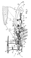
- FIG. 1 which shows an embodiment of a front turbofan
- the gas turbine engine 1 is connected to the structure of the powered aircraft, represented by a wing 2, by a pylon mast 3 whose structure 4 is secured to the outer casing 5 of the engine and which comprises a support pylon 6 to which arms are attached support 7a and 7b.
- the outer casing 5 of the engine comprises a front part 5a and a rear part 5b of aerodynamically profiled shape, generally conical. Front and rear are defined with respect to the direction of movement of the propelled airplane according to arrow F indicated on the airplane part.
- On said outer casing 5 of the engine are circumferentially arranged a multiplicity of channels 8 forming an air inlet sleeve and opening into a first annular stilling chamber 9.
- the air circulates from the front to the rear and from the chamber 9 the air undergoes a first reversal of direction of circulation to circulate from the rear to the front by entering a generator gas 10 which comprises the known and conventional elements but arranged successively in a particular manner to the present invention from the rear to the front: a multi-stage axial compressor 11 at low pressure, then a multi-stage axial compressor 12 at high pressure d '' where the compressed air passes through an annular combustion chamber 13 which supplies hot gases to the turbines driving the compressors, respectively at high pressure 14 and at low pressure 15.
- a generator gas 10 which comprises the known and conventional elements but arranged successively in a particular manner to the present invention from the rear to the front: a multi-stage axial compressor 11 at low pressure, then a multi-stage axial compressor 12 at high pressure d '' where the compressed air passes through an annular combustion chamber 13 which supplies hot gases to the turbines driving the compressors, respectively at high pressure 14 and at low pressure 15.
- the gas generator 10 thus formed is supported and connected to the support pylon 6 by the support arms 7a and 7b fixed to the external casing 16 of the gas generator at the compressor casing, which has the advantage of having the fixing points at cold zone.
- the gas generator 10 is extended forward by an axial gas outlet conduit 17 which routes them to a second annular chamber 18 from which the gases undergo a second reversal of the direction of circulation to circulate from the front to the rear when entering the stages of working turbines arranged in radial superposition external to said duct 17.
- a first turbine rotor 19 comprises several stages of blades 19a, 19b, 19c, 19d, 19th, 19f, the bases of which are fixed on the radially internal side to an internal drum 19g, the downstream end of which forms a cylindrical surface 19h between which and a structural ferrule 20 is disposed a bearing 21.
- the blower 25 comprises an external ring 26 for channeling the secondary flow and an intermediate ring 27 formed by the fins of the blades 28.
- the intermediate ring 27 delimits an external grid which, in the variant shown in FIG. 2, comprises between each pair of blades 28a an intermediate blade 28b so that the external grid has twice as many blades as the internal grid, this arrangement aiming to increase the resistance of the wheel with respect to ingestion.
- This blower of monobloc design is made of composite materials.
- the second slow turbine rotor 29 has six stages 29a to 29f connected by an external drum 29g comprising a front part in the form of a conical sail 30 ending in a cylindrical shell supporting by a flange 31 the disc 32 of the rear blower 33. This this includes blades 34 and an outer ring 35 rotating in the opposite direction to the ring 26 of the front fan.
- the fan 33 includes an intermediate platform 36 forming a ring arranged in the upstream extension of the outer casing 5 of the engine and producing an annular sleeve 37 of air intake for the channels 8 air inlet for hot flow.
- This blower, of monobloc design is also made of composite materials.
- the turbine 29 / fan shaft 30 assembly is mounted rotating at the front inside a structural conical front sail 38 of the engine by means of an upstream bearing 39 and at the rear on the outside of the structural shell 20 by a bearing 40.
- annular gas outlet duct 42 is connected to a multiplicity of channels 43 which open outside the external envelope of the engine around which they are arranged circumferentially, interposed between the 8 air inlet channels.
- the assembly formed by the free turbines 19, 29 and the blowers 25 and 33 form a modular whole which can easily be detached from the front of the gas generator 10 at the level of the labyrinths 44, 45, 46 which seal between the rotating parts and the structural part of the engine.
- the blowers 25 and 33 have vanes with fixed setting.
- This variation in the outlet section of the secondary nozzle can be achieved by means of a deformable device 47 (shown diagrammatically in dotted lines in FIG. 1) carried by the upstream part of the outer casing 5 of the engine.
- the deformable device can be constituted by an outer annular skin which can be inflated radially by aero or hydrodynamic means.
- the deformable device 47 can be constituted by an annular set of longitudinal flaps 48 leading, articulated at their upstream edge on the outer casing 5 and whose downstream edge comprises a hinge 49 of articulation with led flaps 50 located downstream and whose downstream edge slides in longitudinal slides 51 of the envelope 5.
- the flaps 48, 50 can be moved by jacks to form a neck with variable section with the downstream part of the rear outer ring 35 and allow the section variation of the secondary vein.
- a motor as described here may be provided with a secondary flow reversal system formed by panels 52 articulated on their downstream edge on the casing 5 and radially displaceable by jacks to partially block the secondary flow and ensure the cold flow reverse function.
- a secondary flow reversal system formed by panels 52 articulated on their downstream edge on the casing 5 and radially displaceable by jacks to partially block the secondary flow and ensure the cold flow reverse function.
- embodiment of the blowers described above shows monobloc blowers.
- blowers can be produced conventionally with separable vanes mounted in notches of the discs 24 and 32 while the rings 26 and 35 are produced in the form of an assembly of upper platforms of the vanes.
- the blowers may be provided with a device for variable setting of said blades, which avoids the need for a deformable device for varying the section of the secondary vein.
- Such a structure finds its interest in the fact of being able to produce engines with very high dilution rate with tractor blowers with a low master-torque, which facilitates their mounting suspended under the wings of an aircraft, this type of mounting being particularly required for four-jet aircraft.
Landscapes
- Engineering & Computer Science (AREA)
- Chemical & Material Sciences (AREA)
- Combustion & Propulsion (AREA)
- Mechanical Engineering (AREA)
- General Engineering & Computer Science (AREA)
- Structures Of Non-Positive Displacement Pumps (AREA)
Abstract
Description
- La présente invention concerne un moteur à turbine à gaz destiné à la propulsion d'un avion, du genre comportant un générateur de gaz qui alimente deux turbines de travail lentes contrarotatives, imbriquées.
- FR-A-2 535 394 décrit un moteur à turbine à gaz de ce type dans lequel les turbines de travail sont disposées en aval du générateur de gaz et sont entraînées directement par les gaz chauds sortant dudit générateur. Lesdites turbines entrainent directement sans réducteur, soit deux étages d'hélices contrarotatives, soit deux étages de soufflantes carénées par lesquelles est assurée la propulsion. Deux solutions de montage sont proposées. L'une prévoît de disposer les hélices ou les soufflantes à l'arrière du moteur, ce qui présente des inconvénients et des difficultés lors d'un montage sous les ailes d'un avion. L'autre prévoit de les disposer à l'avant du moteur, ce qui impose, pour l'entraînement, des arbres de liaison dont la mise en place comporte également des inconvénients.
- FR-A-2 560 642 décrit un moteur à turbine à gaz du même type dans lequel un compresseur de gavage à contrarotation est associé aux soufflantes avant contrarotatives. Un dispositif de réglage du pas des aubes d'un étage de soufflante est adjoint, permettant d'obtenir une inversion du flux.
- FR-A-2 606 081 décrit un moteur à turbine à gaz du genre précité dans lequel, par rapport au sens de déplacement de l'avion, les gaz circulent dans le générateur de gaz à partir d'une chambre annulaire disposée à l'arrière, vers l'avant et audit générateur de gaz est associée une manche d'entrée d'air composée d'une multiplicité de canaux disposés circonférentiellement autour de l'enveloppe externe du moteur et débouchant dans ladite chambre et dont le sens de circulation des gaz chauds sortant dudit générateur de gaz est inversé pour repartir vers les turbines de travail de l'avant vers l'arrière de telle sorte que la disposition interne du moteur comporte en partant de l'avant vers l'arrière par rapport au sens de déplacement de l'avion propulsé, successivement :
- en superposition radiale partielle, les turbines contrarotatives imbriquées de travail et le conduit axial de sortie du générateur de gaz,
- les étages de turbine du générateur de gaz,
- la chambre de combustion,
- les étages de compression du générateur de gaz,
- la chambre annulaire d'entrée d'air du générateur de gaz. - Selon ce document, les turbines de travail contrarotatives sont associées à deux étages d'hélices contrarotatives placées au même niveau longitudinal, le moteur constituant ainsi un turbopropulseur à hélices avant du type dit "propfan tracteur".
- La présente invention a pour but de présenter une variante du moteur précédemment décrit dans laquelle les soufflantes amont ne sont plus disposées en superposition radiale avec les turbines de travail et le conduit axial de sortie du générateur de gaz mais en avant des turbines de travail ce qui permet de réaliser un moteur possédant le même taux de dilution avec un maître-couple beaucoup moins important.
- L'invention a également pour but de réaliser un sous-ensemble modulaire comportant les turbines de travail contrarotatives et les soufflantes de telle sorte que ledit sous-ensemble soit plus facilement séparable du générateur de gaz par l'avant.
- L'invention a aussi pour but de réaliser un groupe turboréacteur à faible traînée et dont le montage en turboréacteur tracteur sous l'aile d'un avion est facilité.
- L'invention a donc pour objet un moteur à turbine à gaz destiné à la propulsion d'un avion, du genre comportant un générateur de gaz qui alimente deux turbines de travail lentes contrarotatives entrainant deux soufflantes et dans lequel, par rapport au sens de déplacement de l'avion, les gaz circulent dans le générateur de gaz de l'arrière vers l'avant puis de l'avant vers l'arrière dans les turbines libres, caractérisée en ce qu'à la turbine libre radialement interne est associée un arbre central s'étendant vers l'avant du moteur et supportant un disque portant la soufflante avant tandis qu'à la turbine libre radialement externe est associée un tambour avant monté tournant entre l'arbre de soufflante avant et une structure fixe du moteur, ledit tambour portant la soufflante arrière de telle sorte que le moteur comprend de l'avant vers l'arrière et successivement :
- la soufflante avant
- la soufflante arrière et en superposition radiale la manche d'entrée d'air du générateur de gaz, ladite manche étant formée de canaux disposés à l'intérieur de l'enveloppe externe du moteur,
- les turbines libres imbriquées et en superposition radiale, le conduit axial du générateur de gaz,
- la turbine du générateur de gaz
- la chambre de combustion
- le compresseur du générateur de gaz
- une chambre annulaire d'entrée d'air du générateur de gaz. - Selon une particularité de l'invention, la soufflante avant peut comporter un anneau intermédiaire à mi-hauteur des pales de la soufflante et des aubes intermédiaires peuvent être disposées entre l'anneau externe et l'anneau intermédiaire, formant une grille radialement externe de soufflante avant possédant un nombre de pales double de celui de la grille interne.
- D'autres caractéristiques seront précisées dans le complément de description qui va suivre accompagné de planches de dessins parmi lesquelles :
- - la figure 1 est une demi- coupe longitudinale axiale d'un turboréacteur selon l'invention ;
- - la figure 2 est une vue de l'avant de la soufflante amont dans un mode de réalisation comportant un anneau intermédiaire et une couronne externe possédant un nombre d'aubes supérieur à celui de la couronne interne :
- - la figure 3 schématise un mode de réalisation possible d'un moyen de variation de la section secondaire disposé en aval de la soufflante arrière.
- Sur la figure 1, qui représente une réalisation d'une turbosoufflante avant, le moteur à turbine à gaz 1 est relié à la structure de l'avion propulsé, représenté par une aile 2, par un mât-pylône 3 dont la structure 4 est solidaire de l'enveloppe externe 5 du moteur et qui comporte un pylône-support 6 auquel sont fixés des bras- support 7a et 7b. L'enveloppe externe 5 du moteur comporte une partie avant 5a et une partie arrière 5b de forme aérodynamiquement profilée, généralement conique. Avant et arrière sont définis par rapport au sens de déplacement de l'avion propulsé selon la flèche F indiquée sur la partie avion. Sur ladite enveloppe externe 5 du moteur sont disposés circonférentiellement une multiplicité de canaux 8 formant une manche d'entrée d'air et débouchant dans une première chambre annulaire 9 de tranquillisation. Dans les canaux 8, l'air circule de l'avant vers l'arrière et à partir de la chambre 9 l'air subit une première inversion de sens de circulation pour circuler de l'arrière vers l'avant en entrant dans un générateur de gaz 10 qui comporte les éléments connus et classiques mais disposés successivement de manière particulière à la présente invention en partant de l'arrière vers l'avant : un compresseur axial multiétagé 11 à basse pression, puis un compresseur axial multiétagé 12 à haute pression d'où l'air comprimé passe dans une chambre de combustion annulaire 13 qui alimente en gaz chauds les turbines d'entrainement des compresseurs, respectivement à haute pression 14 et à basse pression 15. Le générateur de gaz 10 ainsi constitué est supporté et relié au pylône-support 6 par les bras-supports 7a et 7b fixés à l'enveloppe externe 16 du générateur de gaz au niveau du carter de compresseur, ce qui présente l'avantage de disposer les points de fixation en zone froide. Le générateur de gaz 10 est prolongé vers l'avant par un conduit axial 17 de sortie des gaz qui les achemine à une seconde chambre annulaire 18 à partir de laquelle les gaz subissent une seconde inversion du sens de circulation pour circuler de l'avant vers l'arrière en entrant dans les étages de turbines de travail disposées en superposition radiale externe audit conduit 17. Un premier rotor de turbine 19 comporte plusieurs étages d'aubes 19a, 19b, 19c, 19d, 19e, 19f dont les bases sont fixées du côté radialement interne à un tambour interne 19g dont l'extrémité aval forme une portée cylindrique 19h entre laquelle et une virole structurelle 20 est disposé un palier 21.
- L'extrémité radialement externe des aubes 19a du premier étage de la turbine libre 19 est reliée par un voile conique 22 délimitant la chambre 18 à un arbre central 23 s'étendant vers l'avant 5a du moteur et supportant un disque 24 portant la soufflante avant 25. Dans le mode de réalisation repésenté ici, la soufflante 25 comporte un anneau externe 26 de canalisation du flux secondaire et un anneau intermédiaire 27 formé par des nageoires des pales 28. L'anneau intermédiaire 27 délimite une grille externe qui, dans la variante montrée à la figure 2, comporte entre chaque paire d'aubes 28a une aube intermédiaire 28b de sorte que la grille externe comporte deux fois plus de pales que la grille interne, cette disposition visant à accroître la résistance de la roue vis à vis de l'ingestion. Cette soufflante de conception monobloc est réalisée en matériaux composites.
- Le second rotor 29 de turbine lente comporte six étages 29a à 29f reliés par un tambour externe 29g comportant une partie avant en forme de voile conique 30 se terminant en virole cylindrique supportant par une bride 31 le disque 32 de la soufflante arrière 33. Celle-ci comporte des pales 34 et un anneau externe 35 tournant en sens opposé à l'anneau 26 de la soufflante avant.
- Dans la partie basse des pales 34, la soufflante 33 comporte une plate-forme intermédiaire 36 formant un anneau disposé dans le prolongement amont de l'enveloppe externe 5 du moteur et réalisant une manche 37 annulaire d'entrée d'air pour les canaux 8 d'entrée d'air du flux chaud. Cette soufflante, de conception monobloc est également réalisée en matériaux composites.
- L'ensemble turbine 29/arbre de soufflante 30 est monté tournant à l'avant à l'intérieur d'un voile conique avant structurel 38 du moteur au moyen d'un palier amont 39 et à l'arrière sur l'extérieur de la virole structurelle 20 par un palier 40.
- Un palier amont 41 disposé entre l'arbre central 23 de la soufflante avant et l'arbre 30 de la soufflante arrière permet la rotation de l'arbre 23.
- En arrière des turbines de travail 19 et 29, le conduit annulaire 42 de sortie des gaz se raccorde sur une multiplicité de canaux 43 qui débouchent à l'extérieur de l'enveloppe externe du moteur autour de laquelle ils sont disposés circonférentiellement, intercalés entre les canaux 8 d'entrée d'air.
- Tel que décrit ci-dessus, l'ensemble formé par les turbines libres 19, 29 et les soufflantes 25 et 33 forment un tout modulaire qui peut facilement être désolidarisé par l'avant du générateur de gaz 10 au niveau des labyrinthes 44, 45, 46 qui assurent l'étanchéité entre les parties tournantes et la partie structurelle du moteur.
- Dans le mode de réalisation des soufflantes qui a été décrit ci-dessus, les soufflantes 25 et 33 ont des aubes à calage fixe.
- Comme déja évoqué précédemment elles sont préférablement réalisées monobloc en matériau composite, ce qui permet des applications à des moteurs à très grand taux de dilution, la vitesse périphérique de la carène étant inférieure à 200 m/s. Cette solution a pour intérêt la réduction potentielle de masse qui en résulte.
- Avec des soufflantes à calage fixe, il peut être intéressant de réaliser une variation de section du flux secondaire permettant de contrebalancer l'absence de calage variable des aubes.
- Cette variation de section de sortie de la tuyère secondaire peut être réalisée au moyen d'un dispositif déformable 47 (schématisé en pointillés sur la figure 1) porté par la partie amont de l'enveloppe externe 5 du moteur.
- Le dispositif déformable peut être constitué par une peau annulaire externe gonflable radialement par des moyens aéro-ou hydrodynamiques.
- Dans le mode de réalisation représenté à la figure 3, le dispositif déformable 47 peut être constitué par un ensemble annulaire de volets longitudinaux 48 menants, articulés à leur bord amont sur l'enveloppe externe 5 et dont le bord aval comporte une charnière 49 d'articulation avec des volets menés 50 situés en aval et dont le bord aval coulisse dans des glissières longitudinales 51 de l'enveloppe 5. Les volets 48, 50 peuvent être déplacés par vérins pour former un col à section variable avec la partie aval de l'anneau externe arrière 35 et permettre la variation de section de la veine secondaire.
- Un moteur tel qu'ici décrit peut être doté d'un système d'inversion du flux secondaire formé de panneaux 52 articulés sur leur bord aval sur l'enveloppe 5 et déplaçables radialement par vérins pour venir obturer partiellement l'écoulement secondaire et assurer la fonction de reverse du flux froid. mode de réalisation des soufflantes décrit ci-dessus montre des soufflantes monoblocs.
- Il est évident que les soufflantes peuvent être réalisées classiquement avec des aubes séparables montées dans des encoches des disques 24 et 32 tandis que les anneaux 26 et 35 sont réalisés sous forme d'assemblage de plate-formes supérieurs des aubes.
- Dans le cas où les aubes sont unitaires, les soufflantes peuvent être munies d'un dispositif de calage variable desdites aubes,ce qui évite la nécessité d'un dispositif déformable de variation de la section de la veine secondaire.
- Une telle structure trouve son intérêt dans le fait de pouvoir réaliser des moteurs à très grand taux de dilution à soufflantes tractrices avec un faible maître-couple, ce qui facilite leur montage suspendu sous les ailes d'un avion, ce type de montage étant particulièrement nécessaire pour les avions quadriréacteurs.
Claims (10)
- la soufflante avant (25)
- la soufflante arrière (33) et en superposition radiale la manche (37) d'entrée d'air du générateur de gaz, ladite manche étant formée de canaux (37, 38) disposés à l'intérieur de l'enveloppe externe (5) du moteur,
- les turbines libres (19, 29) imbriquées et en superposition radiale, le conduit axial (17) du générateur de gaz
- la turbine (15, 14) du générateur de gaz
- la chambre de combustion (13)
- les compresseurs (12, 11) du générateur de gaz
- une chambre annulaire (9) d'entrée d'air du générateur de gaz.
Applications Claiming Priority (2)
| Application Number | Priority Date | Filing Date | Title |
|---|---|---|---|
| FR8912630 | 1989-09-27 | ||
| FR8912630A FR2652387B1 (fr) | 1989-09-27 | 1989-09-27 | Moteur de propulsion a soufflantes contrarotatives. |
Publications (2)
| Publication Number | Publication Date |
|---|---|
| EP0420746A1 true EP0420746A1 (fr) | 1991-04-03 |
| EP0420746B1 EP0420746B1 (fr) | 1993-04-07 |
Family
ID=9385855
Family Applications (1)
| Application Number | Title | Priority Date | Filing Date |
|---|---|---|---|
| EP90402643A Expired - Lifetime EP0420746B1 (fr) | 1989-09-27 | 1990-09-26 | Moteur de propulsion à soufflantes contrarotatives |
Country Status (4)
| Country | Link |
|---|---|
| US (1) | US5103635A (fr) |
| EP (1) | EP0420746B1 (fr) |
| DE (1) | DE69001284T2 (fr) |
| FR (1) | FR2652387B1 (fr) |
Cited By (2)
| Publication number | Priority date | Publication date | Assignee | Title |
|---|---|---|---|---|
| EP1777405A2 (fr) * | 2005-10-19 | 2007-04-25 | General Electric Company | Ensemble moteur à turbine à gaz et procédés d'assemblage associés |
| WO2010092094A1 (fr) * | 2009-02-13 | 2010-08-19 | Snecma | Systeme d'helices contrarotatives a encombrement reduit |
Families Citing this family (13)
| Publication number | Priority date | Publication date | Assignee | Title |
|---|---|---|---|---|
| CN100390397C (zh) * | 2005-04-30 | 2008-05-28 | 张鸿元 | 空气压缩航空发动机 |
| US20090249779A1 (en) * | 2006-06-12 | 2009-10-08 | Daw Shien Scientific Research & Development, Inc. | Efficient vapor (steam) engine/pump in a closed system used at low temperatures as a better stirling heat engine/refrigerator |
| US20090211223A1 (en) * | 2008-02-22 | 2009-08-27 | James Shihfu Shiao | High efficient heat engine process using either water or liquefied gases for its working fluid at lower temperatures |
| US20090044535A1 (en) * | 2006-06-12 | 2009-02-19 | Daw Shien Scientific Research And Development, Inc. | Efficient vapor (steam) engine/pump in a closed system used at low temperatures as a better stirling heat engine/refrigerator |
| US20080296906A1 (en) * | 2006-06-12 | 2008-12-04 | Daw Shien Scientific Research And Development, Inc. | Power generation system using wind turbines |
| US20100045037A1 (en) * | 2008-08-21 | 2010-02-25 | Daw Shien Scientific Research And Development, Inc. | Power generation system using wind turbines |
| US8667775B1 (en) * | 2009-08-05 | 2014-03-11 | The Boeing Company | Reverse flow engine core having a ducted fan with integrated secondary flow blades |
| US9970386B2 (en) * | 2013-06-07 | 2018-05-15 | United Technologies Corporation | Exhaust stream mixer |
| US9989011B2 (en) * | 2014-04-15 | 2018-06-05 | United Technologies Corporation | Reverse flow single spool core gas turbine engine |
| US10519860B2 (en) | 2017-03-07 | 2019-12-31 | General Electric Company | Turbine frame and bearing arrangement for three spool engine |
| US10294821B2 (en) | 2017-04-12 | 2019-05-21 | General Electric Company | Interturbine frame for gas turbine engine |
| DE102019006484B3 (de) * | 2019-09-11 | 2020-08-06 | Friedrich Grimm | Mantelstromtriebwerk mit mindestens einer drehmomentstufe |
| US11428160B2 (en) | 2020-12-31 | 2022-08-30 | General Electric Company | Gas turbine engine with interdigitated turbine and gear assembly |
Citations (4)
| Publication number | Priority date | Publication date | Assignee | Title |
|---|---|---|---|---|
| US2426098A (en) * | 1942-09-03 | 1947-08-19 | Armstrong Siddeley Motors Ltd | Compound internal-combustion turbine plant |
| FR1136237A (fr) * | 1954-11-30 | 1957-05-10 | Power Jets Res & Dev Ltd | Perfectionnements apportés aux aubages pour des installations avec turbine à gaz |
| FR2217545A1 (fr) * | 1973-02-12 | 1974-09-06 | Gen Electric | |
| FR2606081A1 (fr) * | 1986-10-29 | 1988-05-06 | Snecma | Moteur de propulsion a turbines de travail contrarotatives |
Family Cites Families (1)
| Publication number | Priority date | Publication date | Assignee | Title |
|---|---|---|---|---|
| GB2196390B (en) * | 1986-10-16 | 1991-06-26 | Rolls Royce Plc | Intake for turbopropeller gas turbine engine. |
-
1989
- 1989-09-27 FR FR8912630A patent/FR2652387B1/fr not_active Expired - Lifetime
-
1990
- 1990-09-07 US US07/578,675 patent/US5103635A/en not_active Expired - Fee Related
- 1990-09-26 DE DE9090402643T patent/DE69001284T2/de not_active Expired - Fee Related
- 1990-09-26 EP EP90402643A patent/EP0420746B1/fr not_active Expired - Lifetime
Patent Citations (4)
| Publication number | Priority date | Publication date | Assignee | Title |
|---|---|---|---|---|
| US2426098A (en) * | 1942-09-03 | 1947-08-19 | Armstrong Siddeley Motors Ltd | Compound internal-combustion turbine plant |
| FR1136237A (fr) * | 1954-11-30 | 1957-05-10 | Power Jets Res & Dev Ltd | Perfectionnements apportés aux aubages pour des installations avec turbine à gaz |
| FR2217545A1 (fr) * | 1973-02-12 | 1974-09-06 | Gen Electric | |
| FR2606081A1 (fr) * | 1986-10-29 | 1988-05-06 | Snecma | Moteur de propulsion a turbines de travail contrarotatives |
Cited By (6)
| Publication number | Priority date | Publication date | Assignee | Title |
|---|---|---|---|---|
| EP1777405A2 (fr) * | 2005-10-19 | 2007-04-25 | General Electric Company | Ensemble moteur à turbine à gaz et procédés d'assemblage associés |
| EP1777405A3 (fr) * | 2005-10-19 | 2012-06-13 | General Electric Company | Ensemble moteur à turbine à gaz et procédés d'assemblage associés |
| WO2010092094A1 (fr) * | 2009-02-13 | 2010-08-19 | Snecma | Systeme d'helices contrarotatives a encombrement reduit |
| FR2942203A1 (fr) * | 2009-02-13 | 2010-08-20 | Snecma | Systeme d'helices contrarotatives a encombrement reduit |
| RU2526130C2 (ru) * | 2009-02-13 | 2014-08-20 | Снекма | Малогабаритная система винтов противоположного вращения |
| US9057326B2 (en) | 2009-02-13 | 2015-06-16 | Snecma | System of compact contra-rotating propellers |
Also Published As
| Publication number | Publication date |
|---|---|
| FR2652387B1 (fr) | 1991-11-29 |
| DE69001284T2 (de) | 1993-08-19 |
| FR2652387A1 (fr) | 1991-03-29 |
| US5103635A (en) | 1992-04-14 |
| EP0420746B1 (fr) | 1993-04-07 |
| DE69001284D1 (de) | 1993-05-13 |
Similar Documents
| Publication | Publication Date | Title |
|---|---|---|
| EP0420746B1 (fr) | Moteur de propulsion à soufflantes contrarotatives | |
| CA2776841C (fr) | Entree d'air de moteur a turbine a gaz dans une nacelle | |
| EP0270403B1 (fr) | Moteur de propulsion à turbines de travail contrarotatives | |
| FR2631079A1 (fr) | Moteur a soufflantes avant, sans boite de vitesse contrarotatives, non canalisees | |
| EP1382817B1 (fr) | Système d'entrainement d'une pompe dans un turbomoteur | |
| EP0395497B1 (fr) | Moteur à soufflantes contrarotatives tractrices | |
| FR2586754A1 (fr) | Moyen de commande d'air, en particulier pour moteur a turbine a gaz | |
| FR2635824A1 (fr) | Turbomoteur a turbine a gaz entrainant par un reducteur des rotors a helices ou des rotors de soufflante | |
| FR2639609A1 (fr) | Dispositif de prise de force, pour convertir en une poussee transversale la puissance developpee par les rotors d'un moteur a turbine a gaz a soufflante non carenee | |
| FR2611229A1 (fr) | Turboreacteur a soufflante carenee a cycle compound | |
| FR2581423A1 (fr) | Turbine de travail a contre-rotation | |
| CA2819384A1 (fr) | Turboreacteur a double flux | |
| FR2601068A1 (fr) | Turbine de puissance pour moteur a turbine a gaz. | |
| FR3100579A1 (fr) | Moteur à turbine à gaz | |
| FR2601075A1 (fr) | Structure de transfert de charge. | |
| FR2464363A1 (fr) | Rotor de turbine pour turbomachines avec systeme de transfert de l'agent de refroidissement | |
| US3548597A (en) | Turbine engine for aircraft having a supplementary compressor driven by a supplementary turbine | |
| FR2645590A1 (fr) | Dispositif de ventilation pour turbine de puissance | |
| FR2605679A1 (fr) | Turboreacteur a rotor tambour, plusieurs corps et plusieurs flux | |
| EP2463197B1 (fr) | Entrée d'air pour ensemble propulsif d'aéronef à structure résistante aux surpressions et procédé de réparation d'une entrée d'air d'ensemble propulsif d'aéronef | |
| FR2951504A1 (fr) | Entree d'air de moteur a turbine a gaz dans une nacelle | |
| FR2992346A1 (fr) | Helice non carenee de turbomachine d'aeronef presentant des pieds de pales refroidis par des conduits d'air de refroidissement traversant les pales | |
| FR3089259A1 (fr) | Turboréacteur à double flux à réducteur | |
| FR2992688A1 (fr) | Helice pourvue d'une nacelle comportant des moyens de compression | |
| FR2560639A1 (fr) | Moyens de commande d'air |
Legal Events
| Date | Code | Title | Description |
|---|---|---|---|
| PUAI | Public reference made under article 153(3) epc to a published international application that has entered the european phase |
Free format text: ORIGINAL CODE: 0009012 |
|
| 17P | Request for examination filed |
Effective date: 19901019 |
|
| AK | Designated contracting states |
Kind code of ref document: A1 Designated state(s): DE FR GB |
|
| 17Q | First examination report despatched |
Effective date: 19920817 |
|
| GRAA | (expected) grant |
Free format text: ORIGINAL CODE: 0009210 |
|
| AK | Designated contracting states |
Kind code of ref document: B1 Designated state(s): DE FR GB |
|
| REF | Corresponds to: |
Ref document number: 69001284 Country of ref document: DE Date of ref document: 19930513 |
|
| GBT | Gb: translation of ep patent filed (gb section 77(6)(a)/1977) |
Effective date: 19930421 |
|
| PLBE | No opposition filed within time limit |
Free format text: ORIGINAL CODE: 0009261 |
|
| STAA | Information on the status of an ep patent application or granted ep patent |
Free format text: STATUS: NO OPPOSITION FILED WITHIN TIME LIMIT |
|
| 26N | No opposition filed | ||
| PGFP | Annual fee paid to national office [announced via postgrant information from national office to epo] |
Ref country code: FR Payment date: 19950809 Year of fee payment: 6 |
|
| PGFP | Annual fee paid to national office [announced via postgrant information from national office to epo] |
Ref country code: GB Payment date: 19950918 Year of fee payment: 6 |
|
| PGFP | Annual fee paid to national office [announced via postgrant information from national office to epo] |
Ref country code: DE Payment date: 19951129 Year of fee payment: 6 |
|
| PG25 | Lapsed in a contracting state [announced via postgrant information from national office to epo] |
Ref country code: GB Effective date: 19960926 |
|
| PG25 | Lapsed in a contracting state [announced via postgrant information from national office to epo] |
Ref country code: FR Effective date: 19960930 |
|
| GBPC | Gb: european patent ceased through non-payment of renewal fee |
Effective date: 19960926 |
|
| PG25 | Lapsed in a contracting state [announced via postgrant information from national office to epo] |
Ref country code: DE Effective date: 19970603 |
|
| REG | Reference to a national code |
Ref country code: FR Ref legal event code: ST |
|
| REG | Reference to a national code |
Ref country code: FR Ref legal event code: ST |