EP0420573B1 - Light quantity control device - Google Patents
Light quantity control device Download PDFInfo
- Publication number
- EP0420573B1 EP0420573B1 EP90310480A EP90310480A EP0420573B1 EP 0420573 B1 EP0420573 B1 EP 0420573B1 EP 90310480 A EP90310480 A EP 90310480A EP 90310480 A EP90310480 A EP 90310480A EP 0420573 B1 EP0420573 B1 EP 0420573B1
- Authority
- EP
- European Patent Office
- Prior art keywords
- light quantity
- output
- control device
- quantity control
- digital value
- Prior art date
- Legal status (The legal status is an assumption and is not a legal conclusion. Google has not performed a legal analysis and makes no representation as to the accuracy of the status listed.)
- Expired - Lifetime
Links
Images


Classifications
-
- H—ELECTRICITY
- H04—ELECTRIC COMMUNICATION TECHNIQUE
- H04N—PICTORIAL COMMUNICATION, e.g. TELEVISION
- H04N1/00—Scanning, transmission or reproduction of documents or the like, e.g. facsimile transmission; Details thereof
- H04N1/40—Picture signal circuits
- H04N1/40025—Circuits exciting or modulating particular heads for reproducing continuous tone value scales
- H04N1/4005—Circuits exciting or modulating particular heads for reproducing continuous tone value scales with regulating circuits, e.g. dependent upon ambient temperature or feedback control
-
- H—ELECTRICITY
- H04—ELECTRIC COMMUNICATION TECHNIQUE
- H04N—PICTORIAL COMMUNICATION, e.g. TELEVISION
- H04N1/00—Scanning, transmission or reproduction of documents or the like, e.g. facsimile transmission; Details thereof
- H04N1/40—Picture signal circuits
- H04N1/40025—Circuits exciting or modulating particular heads for reproducing continuous tone value scales
- H04N1/40037—Circuits exciting or modulating particular heads for reproducing continuous tone value scales the reproducing element being a laser
Definitions
- a semiconductor laser which emits a laser beam is used as a practical light source.
Description
- This invention relates to a light quantity control device adapted for use in a beam recording apparatus or the like.
- In a known image recording apparatus, such as a laser beam printer, a semiconductor laser which emits a laser beam is used as a practical light source.
- The semiconductor laser has an unique light quantity characteristic (I-l characteristic) between a laser driving current "I" and a emitted light quantity "1" as shown in Fig. 13. In Fig. 13, the vertical axis denotes the light quantity "1", and the horizontal axis denotes the laser driving current "I". The semiconductor laser does not emit the laser beam until the laser driving current "I" reaches a threshold value "Ith", but emits the laser beam when the laser driving current "I" exceeds the threshold value "Ith" (such region is referred to generically as the "LED emitting region"). In the laser beam emitting region, the light quantity "1" has a certain slope "α" relative to the laser driving current "I".
- In the known image recording apparatus, the laser is set to a non-emittinq state (i.e., the laser output is set to zero) at first before initiating the printing of each page. The laser driving current "IT" is determined in such a way that a desirable prescribed light quantity "lI" can be obtained by monitoring the laser output and by controlling the laser driving current. The image recording apparatus holds the prescribed light quantity "lT" constant by performing constant-current driving of the laser driving current "lT" corresponding to the prescribed light quantity "lT." However the I-1 characteristic of the semiconductor laser, which has an initial form "A" as shown in Fig. 13, may vary to a form "B" or "C" due to variation in the chip temperature. Accordingly, in the laser beam printer, a constant-current.driving circuit executes light quantity control (APC or auto power control) by clearing the laser output before initiating the printing of each page so as always to perform each printing operation with the desirable prescribed light quantity "lT".
- A method for deciding the current value of the constant-current driving circuit is proposed in U.S. Patent US-A-4,890,288 (corresponding to EP-A2-0258060 published before the present priority date), which method controls the current value by utilizing an IC (D/A converter) for converting a digital value into an analog value.
- However, the conventional light quantity control device, which can control the light quantity characteristic to the driving current of the semiconductor laser by utilizing the D/A converter, suffers from the problem that the bit number of the D/A converter increases in the case where a precise light quantity control is required. That is, the conventional control device takes a lot of time to complete the light quantity control because of the large number of up-counting steps for controlling the drive current increase in the case where the counting operation is initiated from a clear state.
- It is an object of the present invention to provide an improved light quantity control device.
- The invention provides a light quantity control device comprising: beam generating means; monitor means for monitoring the quantity of light of a beam generated by said beam generating means and providing an output; digital value output means for outputting a digital value in accordance with the output of said monitor means, and having first and second modes of operation for varying the digital values at high speed and low speed respectively; and supplying means for supplying a drive current corresponding to the digital value from said digital value output means to said beam generating means; characterised in that a finite response time must elapse before the effect of a change in the digital output value is reflected stably in the output of the monitor means, and in that the digital output value is changed at time intervals shorter than said response time in said first operating mode and not shorter than said response time in said second operating mode.
- Other objects, features, and advantages of the invention will become apparent from the following detailed description of exemplary embodiments of the present invention and the accompanying drawings.
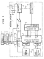
- Fig. 1 is a block diagram showing an arrangement of a light quantity control device according to a embodiment of the present invention;
- Fig. 2A is a chart for explaining output data from the laser light quantity comparator/controller shown in Fig. 1;
- Fig. 2B is a chart showing the relation between the count value shown in Fig. A and the laser current;
- Fig. 3 is a chart showing the relation between the monitor voltage output from the light quantity monitor circuit shown in Fig. 1 and the laser light quantity;
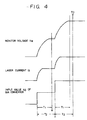
- Fig. 4 is a chart for explaining a low-speed light quantity feedback control sequence of the light quantity control device;
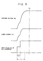
- Fig. 5 is a chart for explaining a high-speed light quantity feedback control sequence of the light quantity control device;
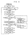
- Fig. 6 is a flow chart for explaining an example of light quantity control procedure in the light quantity control device;
- Fig. 7 is a illustration for explaining a light quantity adjusting timing of the light quantity control device;
- Fig. 8 is a chart showing the relation between the monitor voltage of an initial APC processing and the count value;
- Fig. 9 and Fig. 10 are charts showing the relation between the monitor voltage of an APC processing after the initial APC processing and the count value;
- Fig. 11 is a chart showing an APC processing of the light quantity control device according to a second embodiment of the present invention;
- Fig. 12 is a chart showing an APC processing of a light quantity control device according to a third embodiment of the present invention; and
- Fig. 13 is a chart showing a light quantity characteristic of a light source to which the light quantity control device is applied.
- Three embodiments of the present invention will be described in detail herein with reference to the accompanying drawings.
- Fig. 1 is a block diagram showing an arrangement of a light quantity control device according to the first embodiment of the present invention. The device shown in Fig. 1 includes an
external controller 1, such as a personal computer, for controllingrecording apparatus 3, such as a laser beam printer, by a standard interface (external interface) 4. Well known examples of the standard interface include RS232C, the Centronics interface, and GPIB (general purpose interface bus). The device also includes acontroller 2 for converting data transmitted by thestandard interface 4 into data for ainternal interface 5 provided for the laser beam printer's exclusive use, and for controlling therecording apparatus 3 directly by means of theinternal interface 5. Thecontroller 2 may be mounted on an internal part of therecording apparatus 3 or theexternal controller 1, such as a personal computer, or disposed at an external part of therecording apparatus 3. A central processing unit (CPU) 6 is provided for performing the entire control of the recording apparatus, such as timing control of a motor mounted on the internal part of therecording apparatus 3 and temperature control of a fixing heater, which accompany information recording processing. A laser light quantity comparator/controller 7 composed of a one-chip microcomputer incorporating first and second analog-to-digital (A/D) converters is also provided. TheCPU 6 and the laser light quantity comparator/controller 7 can be structured as a single CPU if the single CPU has a processing capacity which is able to control the control processing conditions properly. The A/D converters may be incorporated into the single CPU or disposed at an external part of the single CPU. - The device also includes a constant-
current control circuit 8, which has a digital-to-analog (D/A)converter 8a connected to outputs Do-Dn of the laser light quantity comparator/controller 7, for converting the outputs Do-Dn (the outputs Do-Dn is used as a count control value) into an analog signal. In the case where the laser light quantity comparator/controller 7 is structured with a microcomputer incorporating a D/A converter, the internal data bus of the microcomputer can constitute the outputs Do-Dn. A constant-current circuit 9 controlled by the constant-current control circuit 8 and receiving a laser current Il through aswitching circuit 10 is provided. Aphotodiode 12 is provided for receiving a laser beam emitted from asemiconductor laser 11 used as a light source. A lightquantity monitor circuit 13 is provided for monitoring a detection signal supplied from thephotodiode 12, and for outputting a light quantity monitor voltage VM to the first A/D converter of the laser light quantity comparator/controller 7. A lightquantity setting circuit 14 structured with a register is provided for outputting an output voltage Vo to the second A/D converter of the laser light quantity comparator/controller 7. The laser light quantity comparator/controller 7 makes and holds a comparison reference value internally by processing the output voltage Vo output from the lightquantity setting circuit 14 internally. AnOR gate 15 is provided for performing OR logic (gate) operation between a video signal VIDEO output through theinternal interface 5 and a laser turning-on signal LON which overrides the data input and unconditionally turns on thesemiconductor laser 11 to execute the light quantity control of the laser. - An operation of the light quantity control device in Fig. 1 will be described below.
- When the
photodiode 12 detects the light quantity of the laser beam emitted from thelaser 11, the D/A converter 8a converts the count control value (outputs Do-Dn) output from the laser light quantity comparator/controller 7 into an analog signal based on the detected light quantity. - In these circumstances, the time required for each change of the count control value is controlled changeably by an output from a timing control means (the laser light quantity comparator/
controller 7 operates as the timing control means in this case) based on the light quantity detected by thephotodiode 12. Accordingly, it is possible to change the time for completing the light quantity control in dependence on the light quantity. - The timing control means executes a low-speed change processing for changing the count control value, which is output to the D/
A converter 8a, after the lapse of a period, used for stabilizing the light quantity of the light beam detected by thephotodiode 12, and enables the constant-current control circuit 8 to execute a constant-current control by giving priority to the stabilization of the light quantity. - The timing control means further executes a high-speed change processing for changing the count control value, which is output to the D/
A converter 8a, before the lapse of the stabilization period for the light quantity of the light beam detected by thephotodiode 12, and enables the constant-current control circuit 8 to execute a constant-current control by giving priority to the shortening of the time necessary for light quantity control. The timing control means executes the low-speed change processing in the range of a reference light quantity value detected by thephotodiode 12, and enables the control of the light quantity while maintaining the stability of the light quantity corresponding to image writing. The D/A converter 8a converts a count control value, which is obtained at the time an initial light quantity adjustment processing of thelaser 11 is completed, sequentially, and outputs the converted count control value as an initial count control value for the next control to the constant-current control circuit 8. Therefore, it is possible to decrease the number of steps used for reaching a light quantity in a stable state, and to reach this light quantity in a short time. - An explanation of data output from the laser light quantity comparator/
controller 7 will be described below with reference to Fig. 2A and Fig. 2B. Fig. 2A is an illustration for explaining data structures of outputs D₀-Dn output from the laser light quantity comparator/controller 7 shown in Fig. 1. Fig. 2A shows the relation between an up-counting of the count value XD and a down-counting of the count value XD. As illustrated in Fig. 2A, the count value XD input to the D/A converter 8a of the constant-current control circuit 8 is represented by an n+1 bit binary number (Dn x 2n + Dn-1 x 2n-1 + ----- + D₃ x 2³ + D2 x 2² + D₁ x 2 + D₀) having the output Dn as the most significant bit (MSB). In Fig. 2A, "0" indicates a low (L) or false level, while "1" indicates a high (H) or true level. - Fig. 2B is a chart showing the relation between the count value XD shown in Fig. 2A and the laser current Il, wherein the vertical axis denotes the laser current Il, and the horizontal axis denotes the count value XD. As shown in Fig. 2B, it is assumed that the laser current Il increases proportionally with the increase of the count value XD.
- Fig. 3 is a chart showing the relation between the monitor voltage VM output from the light
quantity monitor circuit 13 shown in Fig. 1 and the laser light quantity l, where the vertical axis denotes the monitor voltage VM, and the horizontal axis denotes thelaser light quantity 1. - As shown in Fig. 3, the laser beam emitted from the
semiconductor laser 11 is photoelectrically converted by thephotodiode 12 in alaser unit 18, and is processed by the lightquantity monitor circuit 13 to obtain the monitor voltage VM corresponding to thelaser light quantity 1 for feedback to the laser light quantity comparator/controller 7. - Explanations of a low-speed light quantity feedback control and a high-speed light quantity feedback control will be given below with reference to Fig. 4 and Fig. 5.
- Fig. 4 is a chart for explaining the low-speed light quantity feedback control sequence of the light quantity control device. In Fig. 4, the same reference numerals are used to denote the corresponding elements explained in Fig. 2A, Fig. 2B, and Fig. 3.
- In response to the up-counting of the count value XD input to the D/
A converter 8a, the laser current Il increases, thereby increasing the monitor voltage VM. As shown in Fig. 4, in response to the up-counting of the count value XD, a certain time lag occurs until the monitor voltage VM is stabilized. The time lag depends on a time constant or a response of the circuit. - Accordingly, in the case where the low-speed light quantity feedback control is executed, the count value XD is incremented after the lapse of time T2, after being held for a response time T1 (T2 > T1).
- According to the above-described structure, the light quantity can be stabilized although the stabilization of the light quantity control may take time.
- For this reason, the present embodiment employs the low-speed or high-speed light quantity feedback control based on a difference between a predetermined voltage VA and a difference voltage of the monitor voltage VM and a prescribed light quantity voltage VT provided for the
laser 11. Thereby the light quantity control can be completed, at,time T3, at high speed while not affecting the stabilization of the light quantity. - Fig. 5 is a chart for explaining the high-speed light quantity feedback control sequence of the light quantity control device. In Fig. 5, the same reference numerals are used to denote the corresponding elements explained in Fig. 2A, Fig. 2B, and Fig. 3. As shown in Fig. 5, in response to the up-counting of the count value XD input to the D/
A converter 8a, the control decides whether the count value XD is counted up to its proper value or not at the lapse of time T2, rather than the count value XD being held for response time T1 (T2 < T1), which is used for stabilizing the monitor voltage VM. Thereby the upcounting processing of the count value XD is executed at high speed, and the light quantity control can be completed, at time T4, at high speed. - A light quantity control operation of the light quantity control device will be described below with reference to Fig. 6.
- Fig. 6 is a flow chart for explaining an example of the light quantity control procedure in the light quantity control device. In Fig. 6, numerals (1)-(13) denote each step.
- When a power source of the apparatus is turned on, the flow starts, and all information of the printer is cleared.
- In step (1), a closed count value XD1 of the last automatic light quantity control is cleared (i.e., XD1=0). In these circumstances, the laser light quantity comparator/
controller 7 stands by to wait for transmission (TRUE state) of an auto light quantity control start signal (APCST) sent from the CPU6 in step (2). When the auto light quantity control start signal (APCST) is transmitted, the laser light quantity comparator/controller 7 sets the count value XD equal to the closed count value XD1 of the last automatic light quantity control in step (3). The count value XD is used as a input signal to the D/A converter 8a of constant-current circuit 8. In the case where the first automatic light quantity control is performed after turning on the power source, the count value XD is set at "0" because the closed count value XD1 is set at "0" in step (1). The auto light quantity control start signal (APCST) is output during an interval of each recording sheet P1-P3 in the case of consecutive printings shown in Fig. 7. The first auto light quantity control start signal (APCST) is output from the CPU6 just before the image writing to a recording sheet. In step (4), the laser light quantity comparator/controller 7 shifts the laser turning-on signal LON to a true level, to open the gate of the switchingcircuit 10, thereby supplying thesemiconductor laser 11 with a laser current Il. As explained above, the constant-current control circuit 8 having the D/A convertor 8a is controlled by the up-counting or the down-counting of the digital value taken from the outputs D₀-Dn from the laser light quantity comparator/controller 7, thereby varying the laser current Il in thelaser 11 by an analog value corresponding to the up-counting or the down-counting, through the constant-current circuit 9. In step (5), the laser light quantity comparator/controller 7 checks whether a condition | VM - VT | ≦ Va (|VM - VT| shows a difference between the prescribed light quantity voltage VT corresponding to the prescribed light quantity lT and the monitor voltage VM) is satisfied or not. If it is not, the above explained high-speed light quantity feedback control is executed in step (6). In steps (7), the count value is counted down, i.e., a formula XD = XD-1 is executed, if a condition VM - VT ≧ 0 is satisfied, but the count value is counted up, i.e., a formula XD = XD+1 is executed, if a condition VM - VT ≦ 0 is satisfied. Then the flow returns to step (5). In step (7), the step of the count value is not limited to "one"; rather the step of the count value can be set changeably, e.g., "2" or "3" or "n." It is also possible to change the number of steps for up-counting or down-counting in dependence on the monitor voltage VM. - Meanwhile, when in step (5) the answer is yes, the low-speed light quantity feedback control is executed in step (8). In step (9), the laser light quantity comparator/
controller 7 checks whether a condition | VM - VT | ≦ VB is satisfied or not. If it is not, the flow advances to step (10). In step (10), if a condition VM - VT ≧ 0 is satisfied, the count value is counted down, i.e., a formula XD = XD-1 is executed, but if a condition VM - VT < 0 is satisfied, the count value is counted up, i.e., a formula XD = XD+1 is executed. Then the flow returns to step (9). Meanwhile, if the answer in step (9) is yes, the present count value XD is held in an internal memory of the CPU6 as a closed count value XD1 in step (11). - In step (12), laser light quantity comparator/
controller 7 shifts the laser turning-on signal LON to a false level. Consequently, image recording can be performed by the video signal VIDEO sent from thecontroller 2. In step (13), the auto light quantity control is completed. Then the flow returns to step (2). - An explanation of a difference between an auto light quantity control performed at a time when the power source is turned on and an auto light quantity control performed at the next time will be described below with reference to Fig. 8-Fig. 10.
- Fig. 8 is a chart showing the relation between the monitor voltage VM of an initial APC processing and the count value XD, wherein the horizontal axis denotes a time, the upper vertical axis denotes the monitor voltage VM, and the lower vertical axis denotes the count value XD.
- As shown in Fig. 8, the count value XD output from the laser light quantity comparator/
controller 7 to the D/A converter 8a is increased sequentially from "0," and thesemiconductor laser 11 starts to emit the laser beam when the count value XD exceeds a count value corresponding to the threshold value Ith of thesemiconductor laser 11, whereby the monitor voltage VM is output. When the monitor voltage VM is beyond a predetermined voltage (VA), that is, when the monitor voltage VM is within a region A, the count value XD output from the laser light quantity comparator/controller 7 to the D/A converter 8a is counted up at high speed. When the monitor voltage VM is within the predetermined voltage (VA), i.e., a region B, by the up-counting of the count value XD, the low-speed light quantity feedback control is executed. The APC processing is completed when the monitor voltage VM reaches the prescribed light quantity voltage VT. - Fig. 9 and Fig. 10 are charts showing the relation between the monitor voltage VM of an APC processing after the initial APC processing and the count value XD, wherein the horizontal axis denotes time, the upper vertical axis denotes the monitor voltage VM, and the lower vertical axis denotes the count value XD.
- An explanation of the APC processing will be described below with reference to Fig. 6.
- In the case where the count value XD of the last automatic light quantity control is not set at "0," the closed count value XD1 should not be set at "0" in step (3). To put it concretely, the automatic light quantity control (APC) processing is started from a time when the auto light quantity control start signal (APCST) is shifted to a true level. In step (3), a count value set to the D/
A converter 8a in the last automatic light quantity control, that is, the closed count value XD1, is set as the count value XD. In step (5), the monitor voltage VM should be a closed voltage of the last automatic light quantity control corresponding to the count value XD at a time when the laser turning-on signal is shifted to a true level as shown in Fig. 9 or Fig. 10. - In step (5), the laser light quantity comparator/
controller 7 checks the monitor voltage VM. If the condition | VM - VT | ≦ VA is not satisfied, the flow advances to step (6), (7), and the high-speed light quantity feedback control is executed as described above. - Meanwhile, the condition | VM - VT| ≦ VA is often satisfied because the closed count value XD1 of the last automatic light quantity control is adopted. If the condition | VM - VT | ≦ VA is satisfied, the low-speed light quantity feedback control is executed in step (8).
- In step (9), the laser light quantity comparator/
controller 7 checks whether the condition | VM - VT | ≦ VA is satisfied or not. - If it is not, the flow advances to step (10). In step (10), the up-counting (see Fig. 9) or the down-counting (see Fig. 10) of the count value XD is executed, and thereby an appropriate count value XD is set by a fewer number of steps.
- According to the above-described structure, a control time for reaching the prescribed light quantity voltage VT, i.e., a time from the initiation of the APC processing to the completion of the APC processing, can be shortened sharply.
- In the above-described embodiment, the up-counting or the down-counting of the count value XD is performed under the condition that a time for changing the count value is constant. However, in the case where a response of the circuit to the change operation of the count value XD or a sampling time of the CPU6 is slow, the count value XD should be held every predetermined number of up-counting or down-counting as shown in Fig. 9 or Fig. 10. Thereby the count value XD can be counted up or counted down in a state that the monitor voltage VM is stabilized.
- Fig. 11 is a chart showing an APC processing of the light quantity control device according to a second embodiment of the present invention. In Fig. 11, the same reference numerals are used to denote the corresponding elements shown in Fig. 10.
- As shown in Fig. 11, when the power source of the apparatus is turned on, the count value XD received by the D/
A converter 8a starts from "0," i.e., a count value XD(0). When the count value XD coincides with a count value XD(th), the laser current Il exceeds a threshold value current Ith of thesemiconductor laser 11, so that thesemiconductor laser 11 starts to emit the laser beam. - In the case where a response of the circuit to the change operation of the count value XD or a sampling time of the CPU6 is slow, a predetermined number of up-counting steps are executed to obtain a count value XD(A), and the count value XD(A) is held until the monitor voltage VM corresponding to the count value XD(A) is stabilized. After the stabilization of the monitor voltage VM, the up-counting of the count value XD is restarted to execute a predetermined number of up-counting steps for obtaining a count value XD(B). After the predetermined number of up-counting steps are executed, the count value XD(B) is held for stabilizing the monitor voltage VM. When the stabilized monitor voltage VM corresponding to the count value XD(B) is within a predetermined range, that is, when the condition | VM - VT | ≦ VA is satisfied, the above-described low-speed light quantity control is executed, thereby the light quantity is controlled to comply with the prescribed light quantity voltage VT.
- In the above-described embodiment, the light quantity control is carried out by using a count value having a constant step. However, it is possible to shorten the time of the light quantity control by combining such processing where the step for counting is large in the initial control, and the step gets smaller when the light quantity exceeds a predetermined level as shown in U.S. Patent No. 4,890,288 (see Fig. 15).
- Fig. 12 is a chart for showing an APC processing of the light quantity control device according to a third embodiment of the present invention. In Fig. 12, the same reference numerals are used to denote the corresponding elements shown in Fig. 10.
- As shown in Fig. 12, predetermined voltages VA, VB, VC are provided as critical voltages. The high-speed count is increased by 3 counts at a time when the monitor voltage VM is lower than the predetermined voltage VC. The high-speed count is increased by 2 counts at a time when the monitor voltage VM exceeds the predetermined voltage VC. Then, the high-speed count is increased by 1 count at a time when the monitor voltage VM exceeds the predetermined voltage VB. The high-speed count, i.e., the high-speed light quantity feedback control, should be changed over to the low-speed light quantity feedback control when the monitor voltage VM exceeds the predetermined voltage VA.
- According to the above-described structure, a time of the light quantity control can be shortened sharply.
- As mentioned above, according to the present invention, high-speed and high-precision light quantity control can be provided.
- Although particular embodiments of the present invention are herein disclosed for purposes of explanation, various modifications thereof, after study of this specification, will be apparent to those skilled in the art to which the invention pertains.
- In this application, the word "light" will be understood not to be limited to the visible radiation spectrum but to encompass the infra-red region and any other such region of the electromagnetic spectrum as may from time to time be useful in a beam recording apparatus or the like; the wavelength of emission of a beam producing device is readily selectable by the skilled man.
Claims (14)
- A light quantity control device comprising:
beam generating means (11);
monitor means (12, 13) for monitoring the quantity of light of a beam generated by said beam generating means and providing an output;
digital value output means (7) for outputting a digital value in accordance with the output of said monitor means, and having first and second modes of operation for varying the digital values at high speed and low speed respectively; and
supplying means (8a, 8, 9) for supplying a drive current corresponding to the digital value from said digital value output means to said beam generating means;
characterised in that a finite response time (T1) must elapse before the effect of a change in the digital output value is reflected stably in the output of the monitor means, and in that the digital output value is changed at time intervals shorter than said response time in said first operating mode and not shorter than said response time in said second operating mode. - A light quantity control device according to claim 1, wherein said beam generating means comprises a semiconductor laser.
- A light quantity control device according to claim 1 or 2, wherein said monitor means detects the quantity of light of the beam as a monitor voltage.
- A light quantity control device according to claim 1, 2 or 3, wherein said supplying means comprises digital-to-analog converter means (8a) for effecting digital-to-analog conversion of the digital value supplied from said digital value output means and producing an output; driving current control circuit (8) for controlling a drive current for said beam generating means in response to the output of said digital-to-analog converter; and drive current generating means (9) for generating the drive current.
- A light quantity control device according to any preceding claim, wherein said digital value output means operates in the first mode when the output of said monitor means is in a first range, and operates in the second mode when the output of said monitor means in a second range different from the first range.
- A light quantity control device according to any preceding claim, further comprising setting means (14) for setting the value representing the quantity of light of the beam to be generated from said beam generating means.
- A light quantity control device according to claim 6, wherein said digital value output means compares the output from said monitoring means with the value set by said setting means, and varies the digital value output in accordance with the comparison.
- A light quantity control device according to any preceding claim, wherein said digital value output means includes an A/D converter for converting the output from said monitor means into a digital value.
- A light quantity control device according to claim 8, wherein said digital value output means is a micro-computer incorporating the A/D converter.
- A light quantity control device according to any preceding claim, wherein said digital value output means discriminates whether the output of said monitor means reaches a predetermined level and wherein said digital value output means operates in the first mode when the output of said monitor means is discriminated to be lower than the predetermined level, and operates in the second mode when the output of said monitor means is discriminated to reach the predetermined level.
- A light quantity control device according to claim 10, wherein said digital value output means is capable of varying the amount of each change of the digital value in accordance with the output of said monitor means when the output of said monitor means is discriminated to be in a predetermined range lower than the predetermined level.
- A light quantity control device according to claim 10 or 11, further comprising setting means (14) for setting a value representing the quantity of light of the beam to be generated, for comparison with the output of said monitor means, wherein said predetermined level is defined relative to said set value.
- An image recording apparatus including a light quantity control device according to any preceding claim.
- An image recording apparatus according to claim 13, further comprising means for initiating a light quantity control operation of the light quantity control device just before a first image is written to a first recording sheet, and in intervals between the writing of subsequent images on consecutive recording sheets.
Applications Claiming Priority (2)
| Application Number | Priority Date | Filing Date | Title |
|---|---|---|---|
| JP247929/89 | 1989-09-26 | ||
| JP1247929A JP2905229B2 (en) | 1989-09-26 | 1989-09-26 | Light beam drive |
Publications (3)
| Publication Number | Publication Date |
|---|---|
| EP0420573A2 EP0420573A2 (en) | 1991-04-03 |
| EP0420573A3 EP0420573A3 (en) | 1991-08-07 |
| EP0420573B1 true EP0420573B1 (en) | 1995-05-10 |
Family
ID=17170653
Family Applications (1)
| Application Number | Title | Priority Date | Filing Date |
|---|---|---|---|
| EP90310480A Expired - Lifetime EP0420573B1 (en) | 1989-09-26 | 1990-09-25 | Light quantity control device |
Country Status (4)
| Country | Link |
|---|---|
| US (1) | US5151910A (en) |
| EP (1) | EP0420573B1 (en) |
| JP (1) | JP2905229B2 (en) |
| DE (1) | DE69019281T2 (en) |
Families Citing this family (18)
| Publication number | Priority date | Publication date | Assignee | Title |
|---|---|---|---|---|
| CH679816A5 (en) * | 1990-02-15 | 1992-04-15 | Ingbuero Fuer Laser Technologi | |
| JPH0595150A (en) * | 1991-06-28 | 1993-04-16 | Toshiba Corp | Controller for laser |
| EP0536733B1 (en) * | 1991-10-08 | 1998-05-27 | Canon Kabushiki Kaisha | Method for controlling an image forming apparatus |
| JP3255295B2 (en) * | 1991-10-14 | 2002-02-12 | ブラザー工業株式会社 | Image exposure equipment |
| US5237579A (en) * | 1992-01-22 | 1993-08-17 | Ricoh Co. Ltd. | Semiconductor laser controller using optical-electronic negative feedback loop |
| US5442510A (en) * | 1993-06-23 | 1995-08-15 | The United States Of America As Represented By The Secretary Of The Navy | Control system for tracking nonlinear systems |
| US5473360A (en) * | 1993-12-27 | 1995-12-05 | Xerox Corporation | Adaptive method for high speed detection of position and intensity |
| US5604757A (en) * | 1994-05-10 | 1997-02-18 | E-Tek Dynamics, Inc. | Multichannel, programmable laser diode power supply, stabilizer and controller |
| EP0975148B1 (en) * | 1998-07-20 | 2007-01-24 | Maurer Electronics Gmbh | Method for engraving images with radiation on a radiation sensitive layer, especially for laser engraving |
| US6940562B2 (en) * | 2000-04-20 | 2005-09-06 | Canon Kabushiki Kaisha | Controller for remotely controlling two or more controlled devices |
| KR100555728B1 (en) * | 2003-10-16 | 2006-03-03 | 삼성전자주식회사 | Method for controlling laser beam power balence in laser scanning unit |
| JP4535498B2 (en) * | 2005-01-20 | 2010-09-01 | 株式会社リコー | Optical scanning apparatus and image forming apparatus |
| JP4534829B2 (en) * | 2005-03-24 | 2010-09-01 | 富士ゼロックス株式会社 | Light control device |
| US7905038B2 (en) * | 2006-12-27 | 2011-03-15 | Coff Brian R | Container with integrated media display |
| JP4582199B2 (en) | 2008-06-02 | 2010-11-17 | ブラザー工業株式会社 | Optical output device and image forming apparatus provided with the same |
| JP5789567B2 (en) * | 2012-06-25 | 2015-10-07 | 京セラドキュメントソリューションズ株式会社 | Light beam control apparatus and image forming apparatus |
| JP6425475B2 (en) | 2014-09-10 | 2018-11-21 | キヤノン株式会社 | Information processing apparatus capable of controlling mechanical switch of power supply, control method therefor, and program |
| JP6914010B2 (en) * | 2016-05-25 | 2021-08-04 | キヤノン株式会社 | Drive device |
Citations (1)
| Publication number | Priority date | Publication date | Assignee | Title |
|---|---|---|---|---|
| EP0258060A2 (en) * | 1986-08-27 | 1988-03-02 | Canon Kabushiki Kaisha | Light quantity control device |
Family Cites Families (12)
| Publication number | Priority date | Publication date | Assignee | Title |
|---|---|---|---|---|
| JPS59146069A (en) * | 1983-02-08 | 1984-08-21 | Canon Inc | Stabilizing device of light source |
| US4624547A (en) * | 1983-06-28 | 1986-11-25 | Canon Kabushiki Kaisha | Image forming apparatus |
| US4985896A (en) * | 1985-03-29 | 1991-01-15 | Canon Kabushiki Kaisha | Laser driving device |
| US4751523A (en) * | 1986-06-30 | 1988-06-14 | Xerox Corporation | Laser scanner power compensation circuit |
| US4907236A (en) * | 1986-09-19 | 1990-03-06 | Ricoh Company, Ltd. | Method of controlling the quantity of light in a selected range |
| JPS63250966A (en) * | 1987-04-07 | 1988-10-18 | Asahi Optical Co Ltd | Semiconductor laser light power controller |
| DE3883302T2 (en) * | 1987-06-04 | 1994-03-31 | Dainippon Screen Mfg | Device and method for stabilizing the amount of light from a fluorescent lamp. |
| US4926433A (en) * | 1987-10-19 | 1990-05-15 | Ricoh Company, Ltd. | Semiconductor laser unit |
| US4899344A (en) * | 1987-12-07 | 1990-02-06 | Ricoh Co., Ltd. | Semiconductor laser control apparatus |
| US4899348A (en) * | 1987-12-29 | 1990-02-06 | Ricoh Company, Ltd. | Method and apparatus for controlling optical output of laser light source |
| JP2624788B2 (en) * | 1988-07-22 | 1997-06-25 | シャープ株式会社 | Semiconductor laser driver |
| US4972210A (en) * | 1989-06-28 | 1990-11-20 | Eastman Kodak Company | Driver for a diode laser |
-
1989
- 1989-09-26 JP JP1247929A patent/JP2905229B2/en not_active Expired - Fee Related
-
1990
- 1990-09-25 DE DE69019281T patent/DE69019281T2/en not_active Expired - Fee Related
- 1990-09-25 EP EP90310480A patent/EP0420573B1/en not_active Expired - Lifetime
- 1990-09-26 US US07/588,331 patent/US5151910A/en not_active Expired - Lifetime
Patent Citations (1)
| Publication number | Priority date | Publication date | Assignee | Title |
|---|---|---|---|---|
| EP0258060A2 (en) * | 1986-08-27 | 1988-03-02 | Canon Kabushiki Kaisha | Light quantity control device |
Also Published As
| Publication number | Publication date |
|---|---|
| EP0420573A3 (en) | 1991-08-07 |
| DE69019281T2 (en) | 1995-10-12 |
| US5151910A (en) | 1992-09-29 |
| JPH03110583A (en) | 1991-05-10 |
| EP0420573A2 (en) | 1991-04-03 |
| DE69019281D1 (en) | 1995-06-14 |
| JP2905229B2 (en) | 1999-06-14 |
Similar Documents
| Publication | Publication Date | Title |
|---|---|---|
| EP0420573B1 (en) | Light quantity control device | |
| US4890288A (en) | Light quantity control device | |
| US4727382A (en) | Intensity control for a semiconductor laser of a laser beam printer | |
| EP0532743B1 (en) | Direct modulation of laser diodes for radiographic printers | |
| US4807239A (en) | Drive and control circuit for laser diode | |
| US5832012A (en) | Laser scanning unit having automatic power control function | |
| US4907236A (en) | Method of controlling the quantity of light in a selected range | |
| US20030219049A1 (en) | Laser scanning device | |
| US6259466B1 (en) | Light source drive apparatus and image formation apparatus | |
| US5973719A (en) | Laser scanning unit having automatic power control function | |
| US5666150A (en) | Non-uniformity correction for LED printhead in electrophotographic gray scale printing | |
| JPH03202368A (en) | Device for controlling light quantity for laser oscillator | |
| JP2003011410A (en) | Pulse width modulating unit, printer and controlling method thereof | |
| US4856008A (en) | Semiconductor laser control apparatus | |
| JP5713746B2 (en) | Image forming apparatus | |
| JPH066525Y2 (en) | Emergency reset circuit for semiconductor laser drive | |
| US6714231B2 (en) | Image forming apparatus and laser drive control method therein | |
| US6891560B2 (en) | Method of reducing consumption of developer used in electrophotographic processor, and electrophotographic processor performing the method | |
| JP2000330346A (en) | Laser beam quantity controller and control method | |
| JP3113000B2 (en) | Laser power control device | |
| EP0841598A2 (en) | Laser light amount control device and image recording apparatus using the device | |
| EP0536733A1 (en) | Image forming apparatus | |
| JP2001138566A (en) | Image-forming apparatus | |
| JP2798410B2 (en) | Method for controlling emission intensity of semiconductor laser device | |
| JPH0958048A (en) | Light source driver |
Legal Events
| Date | Code | Title | Description |
|---|---|---|---|
| PUAI | Public reference made under article 153(3) epc to a published international application that has entered the european phase |
Free format text: ORIGINAL CODE: 0009012 |
|
| 17P | Request for examination filed |
Effective date: 19901231 |
|
| AK | Designated contracting states |
Kind code of ref document: A2 Designated state(s): DE FR GB IT |
|
| PUAL | Search report despatched |
Free format text: ORIGINAL CODE: 0009013 |
|
| AK | Designated contracting states |
Kind code of ref document: A3 Designated state(s): DE FR GB IT |
|
| 17Q | First examination report despatched |
Effective date: 19930706 |
|
| GRAA | (expected) grant |
Free format text: ORIGINAL CODE: 0009210 |
|
| AK | Designated contracting states |
Kind code of ref document: B1 Designated state(s): DE FR GB IT |
|
| REF | Corresponds to: |
Ref document number: 69019281 Country of ref document: DE Date of ref document: 19950614 |
|
| ITF | It: translation for a ep patent filed |
Owner name: SOCIETA' ITALIANA BREVETTI S.P.A. |
|
| ET | Fr: translation filed | ||
| PLBE | No opposition filed within time limit |
Free format text: ORIGINAL CODE: 0009261 |
|
| STAA | Information on the status of an ep patent application or granted ep patent |
Free format text: STATUS: NO OPPOSITION FILED WITHIN TIME LIMIT |
|
| 26N | No opposition filed | ||
| REG | Reference to a national code |
Ref country code: GB Ref legal event code: IF02 |
|
| PGFP | Annual fee paid to national office [announced via postgrant information from national office to epo] |
Ref country code: GB Payment date: 20060918 Year of fee payment: 17 |
|
| PGFP | Annual fee paid to national office [announced via postgrant information from national office to epo] |
Ref country code: IT Payment date: 20060930 Year of fee payment: 17 |
|
| PGFP | Annual fee paid to national office [announced via postgrant information from national office to epo] |
Ref country code: DE Payment date: 20061122 Year of fee payment: 17 |
|
| GBPC | Gb: european patent ceased through non-payment of renewal fee |
Effective date: 20070925 |
|
| PG25 | Lapsed in a contracting state [announced via postgrant information from national office to epo] |
Ref country code: DE Free format text: LAPSE BECAUSE OF NON-PAYMENT OF DUE FEES Effective date: 20080401 |
|
| REG | Reference to a national code |
Ref country code: FR Ref legal event code: ST Effective date: 20080531 |
|
| PG25 | Lapsed in a contracting state [announced via postgrant information from national office to epo] |
Ref country code: FR Free format text: LAPSE BECAUSE OF NON-PAYMENT OF DUE FEES Effective date: 20071001 |
|
| PGFP | Annual fee paid to national office [announced via postgrant information from national office to epo] |
Ref country code: FR Payment date: 20060926 Year of fee payment: 17 |
|
| PG25 | Lapsed in a contracting state [announced via postgrant information from national office to epo] |
Ref country code: GB Free format text: LAPSE BECAUSE OF NON-PAYMENT OF DUE FEES Effective date: 20070925 |
|
| PG25 | Lapsed in a contracting state [announced via postgrant information from national office to epo] |
Ref country code: IT Free format text: LAPSE BECAUSE OF NON-PAYMENT OF DUE FEES Effective date: 20070925 |