EP0420460A1 - Knee prosthesis - Google Patents
Knee prosthesis Download PDFInfo
- Publication number
- EP0420460A1 EP0420460A1 EP90310084A EP90310084A EP0420460A1 EP 0420460 A1 EP0420460 A1 EP 0420460A1 EP 90310084 A EP90310084 A EP 90310084A EP 90310084 A EP90310084 A EP 90310084A EP 0420460 A1 EP0420460 A1 EP 0420460A1
- Authority
- EP
- European Patent Office
- Prior art keywords
- femoral
- knee
- tibial
- prosthesis
- members
- Prior art date
- Legal status (The legal status is an assumption and is not a legal conclusion. Google has not performed a legal analysis and makes no representation as to the accuracy of the status listed.)
- Granted
Links
- 210000003127 knee Anatomy 0.000 title claims abstract description 42
- 238000006243 chemical reaction Methods 0.000 claims abstract description 3
- 229910052751 metal Inorganic materials 0.000 claims description 9
- 239000002184 metal Substances 0.000 claims description 9
- 239000004033 plastic Substances 0.000 claims description 7
- 229920003023 plastic Polymers 0.000 claims description 7
- 239000000463 material Substances 0.000 claims description 5
- 210000002303 tibia Anatomy 0.000 abstract description 6
- 210000000689 upper leg Anatomy 0.000 abstract description 5
- 210000004417 patella Anatomy 0.000 description 6
- 210000000988 bone and bone Anatomy 0.000 description 4
- 241001227561 Valgus Species 0.000 description 3
- 239000002245 particle Substances 0.000 description 3
- 238000001356 surgical procedure Methods 0.000 description 3
- 241000469816 Varus Species 0.000 description 2
- 230000015572 biosynthetic process Effects 0.000 description 2
- 238000005755 formation reaction Methods 0.000 description 2
- 210000002414 leg Anatomy 0.000 description 2
- 206010023204 Joint dislocation Diseases 0.000 description 1
- 206010033372 Pain and discomfort Diseases 0.000 description 1
- 239000004699 Ultra-high molecular weight polyethylene Substances 0.000 description 1
- 230000001133 acceleration Effects 0.000 description 1
- 230000001174 ascending effect Effects 0.000 description 1
- 210000004204 blood vessel Anatomy 0.000 description 1
- 230000037182 bone density Effects 0.000 description 1
- 239000004568 cement Substances 0.000 description 1
- 239000007943 implant Substances 0.000 description 1
- 238000002513 implantation Methods 0.000 description 1
- 210000000629 knee joint Anatomy 0.000 description 1
- 238000013150 knee replacement Methods 0.000 description 1
- 230000014759 maintenance of location Effects 0.000 description 1
- 238000004519 manufacturing process Methods 0.000 description 1
- 230000000149 penetrating effect Effects 0.000 description 1
- 230000000717 retained effect Effects 0.000 description 1
- 230000000630 rising effect Effects 0.000 description 1
- 229920000785 ultra high molecular weight polyethylene Polymers 0.000 description 1
- 239000000602 vitallium Substances 0.000 description 1
Images


Classifications
-
- A—HUMAN NECESSITIES
- A61—MEDICAL OR VETERINARY SCIENCE; HYGIENE
- A61F—FILTERS IMPLANTABLE INTO BLOOD VESSELS; PROSTHESES; DEVICES PROVIDING PATENCY TO, OR PREVENTING COLLAPSING OF, TUBULAR STRUCTURES OF THE BODY, e.g. STENTS; ORTHOPAEDIC, NURSING OR CONTRACEPTIVE DEVICES; FOMENTATION; TREATMENT OR PROTECTION OF EYES OR EARS; BANDAGES, DRESSINGS OR ABSORBENT PADS; FIRST-AID KITS
- A61F2/00—Filters implantable into blood vessels; Prostheses, i.e. artificial substitutes or replacements for parts of the body; Appliances for connecting them with the body; Devices providing patency to, or preventing collapsing of, tubular structures of the body, e.g. stents
- A61F2/02—Prostheses implantable into the body
- A61F2/30—Joints
- A61F2/38—Joints for elbows or knees
- A61F2/3836—Special connection between upper and lower leg, e.g. constrained
- A61F2/384—Special connection between upper and lower leg, e.g. constrained hinged, i.e. with transverse axle restricting the movement
- A61F2/385—Special connection between upper and lower leg, e.g. constrained hinged, i.e. with transverse axle restricting the movement also provided with condylar bearing surfaces
Definitions
- the present invention relates to a knee prosthesis for implanting into a leg.
- Knee prostheses in which a femoral member and a tibial member are hinged together are known.
- One such prosthesis is the so-called Stanmore hinged knee (see Lettin A. W. F., J. Bone Joint Surg, 1978, 60-b, 327-332.
- Another such prosthesis is the Attenborough knee (see Attenborough C. G., J. Bone Joint Surge, 1978, 60-b, 320-6).
- the present invention provides a hinged knee replacement with provision for limited rotation at the knee so that twisting forces are less likely to be transmitted to the cemented joints between the prosthesis and the tibia and femur.
- the invention provides a knee prosthesis comprising a femoral member connected to a tibial member by a hinge that permits twisting of the knee.
- the prosthesis preferably includes means that forces the femoral member and the tibial member apart upon twisting of the knee so that weight applied through the knee has an untwisting action.
- the tibial member has a support for condylar surfaces of the femoral member to produce a reaction to at least part and preferably to a major part of the weight on the femoral member.
- the prosthesis has an extended position defined by abutment of an anterior portion of the condylar surfaces with a support. If the support is a member of low-friction plastics material that is carried on and fits into the tibial member, metal to metal contact at the extended position of the knee is avoided.
- a hinge axle having a cylindrical outer surface fits into a pivot hole of the femoral member that has enlarged ends and is internally shaped so as to roll on the axle as it twists .
- the femoral member is positioned transversely of the knee by medial and lateral ball formations that fit between corresponding socket formations that are non-twistable relative to the tibial member .
- the axle is defined by a pin which is preferably metallic and by a pair of bushes that are preferably of plastics and fit onto the axle from opposite ends with end flanges of the bushes fitting between the femoral and tibial members.
- the socket surfaces are then formed on inner faces of the flanges.
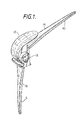
- Figure 1 shows a Stanmore knee which has been implanted into over 10,000 patients since 1968. Further surgery in a minority of patients has been required because of loosening of fixation, fracture of one or other of the intramedullary stems 10, 11 and other causes. There are a number of other features of this knee which could be improved.
- the patella flange 12 is narrow and not very anatomic in profile and shape. This has resulted in subluxation and dislocation of the patella with consequential retropatella pain and discomfort.
- the hinge axis 13 is more anterior than the anatomic knee hinge position, resulting in a reduced lever arm of the patella and consequential extension lag and reduced quadriceps efficiency particularly when rising from a chair or when ascending stairs.
- the hinge is relatively narrow and high moments acting on it result in excessive wear of plastics axle bushes fitted into the knee which results in varus valgus instability. Particles which have become detached from the prosthesis as a result of wear have nowhere to escape and accelerate wear of the hinge surfaces.
- the hyperextension stop that defines the unflexed position of the knee occurs on abutment of anterior portions of the femoral and tibial components 14, 15 relatively compact areas, with direct metal to metal contact, further aggravating the debris from wear of the metal.
- the torsional rigidity of the Stanmore knee can not only cause loosening of the implant but in two cases known to the applicants has caused torsional fractures of the femur.
- the Stanmore knee is simple to manufacture and can be fitted to a patient by a relatively simple and quick surgical procedure which has accounted for its popularity notwithstanding the problems mentioned above.
- An object of the invention is to provide a knee prosthesis for implantation into patients that is not significantly more complicated than the Stanmore knee and is surgically simple to fit but which does not suffer from the problems of that knee.
- a knee prosthesis comprises a femoral member 20 and a tibial member 22 which are each cast in a hard physiologically acceptable metal, for example cobalt chromium molybdenum alloy.
- the members 20, 22 are hingedly connected by a two-part axle consisting of an inner metallic axle pin 24 and a pair of axle bushes of plastics material 26, 28 that fit onto the axle pin 24.
- the femoral member 20 has anatomically shaped and profiled condylar surfaces 32 leading to a broad patella flange 34 whose antero-proximal aspect 35 is shaped according to whether the knee is for the left or the right leg and which minimizes interference with the various blood vessels penetrating the bony cortex of the femur in the region of the patella.
- a transverse pivot hole 36 is located in or close to an anatomic position at the effective centre of rotation of the condylar surfaces 32, thus maintaining the natural lever arm of the patella and giving good quadriceps efficiency.
- the member 20 has convex spherical medial and lateral surfaces 38, 40 which locate and mate with corresponding concave seating surfaces 68, 69 of the bushes 26, 28 so that the femoral member rotates in and is located along a transverse direction by a ball joint.
- a femoral inter-medullary stem tapered with four flats is set at a genu-vagum angle of 7° and arises from a femoral plateau 44 formed with tightening holes 46 that also act to reinforce the cement mantle and improve the torsional fixing.
- the tibial member 22 has a tibial tray 50 from the lower face of which a tibial intermedullary stem 52 depends at an angle of 3° of valgus. Because the stems 42, 52 are angled and the tray 50 is shaped to confirm to the top of the tibia , each component of the knee is left- or righthanded.
- a pair of anti-rotation pylons 54 spaced from the stem 52 depend from the tray 50 and are located so as to correspond to regions of greatest bone density.
- a recess 56 is formed in a proximal region of the tibial tray 50 and the tibial bearing member 30 is a snap fit into the recess 56.
- tibial tray 50 is relatively large and when implanted extends over substantially the whole of the head of the tibia.
- the axle is in two parts with the bushes 26, 28 that define the outer portion fitting loosely from opposite ends into the pivot hole 36 and abutting midway along the pivot hole.
- the concave socket surfaces 68, 69 locate on and slide freely over the medial and lateral surfaces 38, 40 of the femoral member 20.
- the member 20 carrying the bushes 22 fits closely between the medial and lateral lugs 58, 60 of the tibial member 22, after which the axle pin can be passed through the apertures 61, 62 and the bushes 26, 28 and held in place by circlips to complete assembly of the joint.
- the bushes 26, 28 are twice as long as the corresponding bushes in the Stanmore hinge, which is expected to reduce the peak lateral contact stresses by a factor of 8.
- the tibial bearing member 30 is formed with dished bearing surfaces 47, 48 conforming to the curvature of the condylar surfaces 32 which allow for articulation of the members 20, 22 when the prosthesis is flexed and which provide support when the prosthesis is unflexed.
- an anterior portion of the condylar surfaces 32 abuts and anterior portion of the bearing member 30 to provide a hyperextension stop without metal to metal contact.
- condylar surfaces 32 slide over posterior regions of the member 30 when the knee is flexed and return when the knee is unflexed until the anterior portions of the condylar surfaces 30 and the member 32 abut to define the hyperextended or unflexed position.
- the involute or reverse barrel shape of the pivot hole 36 permits torsional laxity of the hinge joint of up to 8°, the joint being controlled by the ball surfaces 38, 40 that fit into the socket surfaces 68, 69. It is expected that the loads on the bushes 26, 28 will be relatively light, and consequently that there will be few wear problems.
- the divergent or barrel form of the pivot hole 36 provides a route for egress of any particles that become detached as a result of wear, thus reducing acceleration of wear through retention of particles between the hinge surfaces.
- the prosthesis described above provides controlled flexion and extension together with a high degree of medial-lateral stability for varus valgus movements.
- There is good conformity of the bearing surfaces which gives good kinematic location, and the relatively low contact stresses expected should give reduced wear and improved joint life.
- the various bearing surfaces are spherical or involute which avoids high point contact stresses).
- the torsional articulation between the femoral member 20 and the bushes 26, 28 of the axle can allow internal-external rotation of typically up to about 8°.
- the condylar surfaces 32 ride up on the dished surfaces 47, 48 of the bearing member 30 and when the patient's weight is applied to the knee joint the axial load thereon provides a returning or centralizing torque which is similar to the screw-home axis of the knee described by some anatomists.
Abstract
Description
- The present invention relates to a knee prosthesis for implanting into a leg.
- Knee prostheses in which a femoral member and a tibial member are hinged together are known. One such prosthesis is the so-called Stanmore hinged knee (see Lettin A. W. F., J. Bone Joint Surg, 1978, 60-b, 327-332. Another such prosthesis is the Attenborough knee (see Attenborough C. G., J. Bone Joint Surge, 1978, 60-b, 320-6). Although many patients have been treated successfully with these knees, further surgery has been required in a number of patients because the joints have loosened or become broken (see R. J. Grimer, J. Bone Joint Surg 1984, 66-b, 55 and C. J. Kershaw, J. Bone Joint Surg 1988, 70-b, 89).
- The present invention provides a hinged knee replacement with provision for limited rotation at the knee so that twisting forces are less likely to be transmitted to the cemented joints between the prosthesis and the tibia and femur.
- The invention provides a knee prosthesis comprising a femoral member connected to a tibial member by a hinge that permits twisting of the knee.
- For provision of a returning or centralising centralising torque the prosthesis preferably includes means that forces the femoral member and the tibial member apart upon twisting of the knee so that weight applied through the knee has an untwisting action. In order to minimize wear at the hinge axle the tibial member has a support for condylar surfaces of the femoral member to produce a reaction to at least part and preferably to a major part of the weight on the femoral member. In a further feature, the prosthesis has an extended position defined by abutment of an anterior portion of the condylar surfaces with a support. If the support is a member of low-friction plastics material that is carried on and fits into the tibial member, metal to metal contact at the extended position of the knee is avoided.
- In order to permit twisting of the knee, a hinge axle having a cylindrical outer surface fits into a pivot hole of the femoral member that has enlarged ends and is internally shaped so as to roll on the axle as it twists . The femoral member is positioned transversely of the knee by medial and lateral ball formations that fit between corresponding socket formations that are non-twistable relative to the tibial member . The axle is defined by a pin which is preferably metallic and by a pair of bushes that are preferably of plastics and fit onto the axle from opposite ends with end flanges of the bushes fitting between the femoral and tibial members. The socket surfaces are then formed on inner faces of the flanges.
- The invention will now be further described, by way of example only, with reference to the accompanying drawings in which:
- Figure 1 is a perspective view of a Stanmore knee in a partly flexed position;
- Figure 2 is a view of a knee prosthesis according to the invention in a flexed position;
- Figure 3 is a perspective exploded view of the knee prosthesis of Figure 2;
- Figure 4 is a front view of the prosthesis when unflexed: and
- Figure 5 is a view of the prosthesis in transverse section.
- In the drawings, Figure 1 shows a Stanmore knee which has been implanted into over 10,000 patients since 1968. Further surgery in a minority of patients has been required because of loosening of fixation, fracture of one or other of the
intramedullary stems 10, 11 and other causes. There are a number of other features of this knee which could be improved. Thepatella flange 12 is narrow and not very anatomic in profile and shape. This has resulted in subluxation and dislocation of the patella with consequential retropatella pain and discomfort. Thehinge axis 13 is more anterior than the anatomic knee hinge position, resulting in a reduced lever arm of the patella and consequential extension lag and reduced quadriceps efficiency particularly when rising from a chair or when ascending stairs. The hinge is relatively narrow and high moments acting on it result in excessive wear of plastics axle bushes fitted into the knee which results in varus valgus instability. Particles which have become detached from the prosthesis as a result of wear have nowhere to escape and accelerate wear of the hinge surfaces. The hyperextension stop that defines the unflexed position of the knee occurs on abutment of anterior portions of the femoral andtibial components - An object of the invention is to provide a knee prosthesis for implantation into patients that is not significantly more complicated than the Stanmore knee and is surgically simple to fit but which does not suffer from the problems of that knee.
- In Figures 2 to 5, a knee prosthesis comprises a
femoral member 20 and atibial member 22 which are each cast in a hard physiologically acceptable metal, for example cobalt chromium molybdenum alloy. Themembers metallic axle pin 24 and a pair of axle bushes ofplastics material axle pin 24. A tibial bearingmember 30 of low-friction plastics material, for example ultra high molecular weight polyethylene. fits between the femoral andtibial members - The
femoral member 20 has anatomically shaped and profiledcondylar surfaces 32 leading to abroad patella flange 34 whose antero-proximal aspect 35 is shaped according to whether the knee is for the left or the right leg and which minimizes interference with the various blood vessels penetrating the bony cortex of the femur in the region of the patella. Atransverse pivot hole 36 is located in or close to an anatomic position at the effective centre of rotation of thecondylar surfaces 32, thus maintaining the natural lever arm of the patella and giving good quadriceps efficiency. Themember 20 has convex spherical medial andlateral surfaces concave seating surfaces bushes femoral plateau 44 formed with tighteningholes 46 that also act to reinforce the cement mantle and improve the torsional fixing. - The
tibial member 22 has atibial tray 50 from the lower face of which a tibialintermedullary stem 52 depends at an angle of 3° of valgus. Because thestems tray 50 is shaped to confirm to the top of the tibia , each component of the knee is left- or righthanded. A pair ofanti-rotation pylons 54 spaced from thestem 52 depend from thetray 50 and are located so as to correspond to regions of greatest bone density. Arecess 56 is formed in a proximal region of thetibial tray 50 and the tibial bearingmember 30 is a snap fit into therecess 56. Medial andlateral lugs tray 50 are formed withapertures tibial tray 50 is relatively large and when implanted extends over substantially the whole of the head of the tibia. - As previously stated, the axle is in two parts with the
bushes pivot hole 36 and abutting midway along the pivot hole. Theconcave socket surfaces lateral surfaces femoral member 20. Themember 20 carrying thebushes 22 fits closely between the medial andlateral lugs tibial member 22, after which the axle pin can be passed through theapertures bushes bushes - In the Stanmore hinge the whole of the patient's weight is taken on the hinge bushes, whereas in the present knee a major proportion of the patient's weight is transmitted through the
condylar surfaces 32 to the tibia. For this purpose, the tibial bearingmember 30 is formed with dished bearingsurfaces condylar surfaces 32 which allow for articulation of themembers condylar surfaces 32 abuts and anterior portion of thebearing member 30 to provide a hyperextension stop without metal to metal contact. Thus thecondylar surfaces 32 slide over posterior regions of themember 30 when the knee is flexed and return when the knee is unflexed until the anterior portions of thecondylar surfaces 30 and themember 32 abut to define the hyperextended or unflexed position. - The involute or reverse barrel shape of the
pivot hole 36 permits torsional laxity of the hinge joint of up to 8°, the joint being controlled by theball surfaces socket surfaces bushes pivot hole 36 provides a route for egress of any particles that become detached as a result of wear, thus reducing acceleration of wear through retention of particles between the hinge surfaces. - The prosthesis described above provides controlled flexion and extension together with a high degree of medial-lateral stability for varus valgus movements. There is good conformity of the bearing surfaces which gives good kinematic location, and the relatively low contact stresses expected should give reduced wear and improved joint life. (It will be noted that the various bearing surfaces are spherical or involute which avoids high point contact stresses). The torsional articulation between the
femoral member 20 and thebushes condylar surfaces 32 ride up on thedished surfaces bearing member 30 and when the patient's weight is applied to the knee joint the axial load thereon provides a returning or centralizing torque which is similar to the screw-home axis of the knee described by some anatomists.
Claims (7)
Applications Claiming Priority (2)
| Application Number | Priority Date | Filing Date | Title |
|---|---|---|---|
| GB8921753 | 1989-09-27 | ||
| GB8921753A GB2237200B (en) | 1989-09-27 | 1989-09-27 | Knee prosthesis |
Publications (2)
| Publication Number | Publication Date |
|---|---|
| EP0420460A1 true EP0420460A1 (en) | 1991-04-03 |
| EP0420460B1 EP0420460B1 (en) | 1994-11-30 |
Family
ID=10663656
Family Applications (1)
| Application Number | Title | Priority Date | Filing Date |
|---|---|---|---|
| EP90310084A Expired - Lifetime EP0420460B1 (en) | 1989-09-27 | 1990-09-14 | Knee prosthesis |
Country Status (5)
| Country | Link |
|---|---|
| EP (1) | EP0420460B1 (en) |
| AT (1) | ATE114447T1 (en) |
| DE (1) | DE69014528T2 (en) |
| ES (1) | ES2065495T3 (en) |
| GB (1) | GB2237200B (en) |
Cited By (15)
| Publication number | Priority date | Publication date | Assignee | Title |
|---|---|---|---|---|
| WO1994021198A1 (en) * | 1993-03-15 | 1994-09-29 | University College London | Total knee replacement prosthesis |
| EP0791343A2 (en) * | 1996-02-21 | 1997-08-27 | Plus Endoprothetik Ag | Knee joint endoprosthesis |
| EP1252870A1 (en) * | 2001-04-25 | 2002-10-30 | Waldemar Link (GmbH & Co.) | Knee prosthesis with a bending hinge |
| US6485519B2 (en) | 2001-01-29 | 2002-11-26 | Bristol-Myers Squibb Company | Constrained prosthetic knee with rotating bearing |
| EP1384454A1 (en) * | 2002-07-26 | 2004-01-28 | WALDEMAR LINK GmbH & Co. KG | Knee prothesis |
| US6719800B2 (en) | 2001-01-29 | 2004-04-13 | Zimmer Technology, Inc. | Constrained prosthetic knee with rotating bearing |
| US6773461B2 (en) | 2001-01-29 | 2004-08-10 | Zimmer Technology, Inc. | Constrained prosthetic knee with rotating bearing |
| US8523950B2 (en) | 2006-06-30 | 2013-09-03 | Smith & Nephew, Inc. | Anatomical motion hinged prosthesis |
| US8545570B2 (en) | 2001-12-21 | 2013-10-01 | Smith & Nephew, Inc. | Hinged joint system |
| WO2017013428A1 (en) * | 2015-07-20 | 2017-01-26 | Fitzbionics Limited | Total knee replacement prosthesis assembly |
| US9642711B2 (en) | 2003-10-17 | 2017-05-09 | Smith & Nephew, Inc. | High flexion articular insert |
| US9707087B2 (en) | 2002-12-20 | 2017-07-18 | Smith & Nephew, Inc. | High performance knee prosthesis |
| CN108186167A (en) * | 2018-01-23 | 2018-06-22 | 北京爱康宜诚医疗器材有限公司 | Knee-joint prosthesis |
| CN109248010A (en) * | 2017-07-14 | 2019-01-22 | 德普伊爱尔兰无限公司 | System and method for orthopedic joint replacement operation |
| WO2019018266A1 (en) * | 2017-07-17 | 2019-01-24 | Aaron Marlow | Tapered fixation device for a knee replacement |
Families Citing this family (4)
| Publication number | Priority date | Publication date | Assignee | Title |
|---|---|---|---|---|
| US5282867A (en) * | 1992-05-29 | 1994-02-01 | Mikhail Michael W E | Prosthetic knee joint |
| DE69822266T2 (en) * | 1997-11-03 | 2005-02-24 | DePuy Orthopaedics, Inc., Warsaw | Modular elbow prosthesis |
| US7261740B2 (en) | 2003-10-29 | 2007-08-28 | Wright Medical Technology, Inc. | Tibial knee prosthesis |
| CN113069246B (en) * | 2021-03-31 | 2022-10-14 | 北京市春立正达医疗器械股份有限公司 | Double-acting knee joint prosthesis |
Citations (10)
| Publication number | Priority date | Publication date | Assignee | Title |
|---|---|---|---|---|
| FR2076838A5 (en) * | 1970-01-30 | 1971-10-15 | Lyon Ass Arts Et Metiers | |
| DE2122390A1 (en) * | 1971-05-06 | 1973-01-04 | Aesculap Werke Ag | KNEE JOINT ENDOPROTHESIS |
| US3837009A (en) * | 1972-12-07 | 1974-09-24 | New York Soc Relief Of Rupture | Knee prosthesis |
| US3909854A (en) * | 1973-05-03 | 1975-10-07 | Ysidore M Martinez | Knee implant prosthesis |
| GB1457147A (en) * | 1974-11-19 | 1976-12-01 | Univ Melbourne | Prosthetic knee joint |
| DE2539717A1 (en) | 1975-09-06 | 1977-03-17 | Wolfram Fischer | Rotatable internal knee joint prosthesis - permits easy manipulation during implantation and simulates normal knee movement |
| FR2330377A1 (en) * | 1975-11-06 | 1977-06-03 | Schuett & Grundei Sanitaet | BALL ENDOPROTHESIS |
| FR2445137A1 (en) * | 1978-12-29 | 1980-07-25 | Deaux Ets | Knee prosthesis permitting rotary and bending motion - has hinge joint between tibial and femoral components with cammed, profiled surfaces cooperating with tibial stem |
| WO1989006947A1 (en) * | 1988-02-02 | 1989-08-10 | Joint Medical Products Corporation | Prosthetic joint |
| FR2628316A1 (en) * | 1988-03-08 | 1989-09-15 | Lebeguec Pierre | Whole knee prosthesis - has one piece implanted at end of femur, other at end of tibia articulating around cross member of T=piece |
Family Cites Families (7)
| Publication number | Priority date | Publication date | Assignee | Title |
|---|---|---|---|---|
| US3813700A (en) * | 1973-04-16 | 1974-06-04 | S Tennant | Prosthetic knee device |
| US4301553A (en) * | 1975-08-15 | 1981-11-24 | United States Surgical Corporation | Prosthetic knee joint |
| US4219893A (en) * | 1977-09-01 | 1980-09-02 | United States Surgical Corporation | Prosthetic knee joint |
| BR7506468A (en) * | 1975-10-03 | 1975-12-02 | S Eshriqui | ARTICULATED KNEE PROSTHESIS |
| US4136405A (en) * | 1977-04-29 | 1979-01-30 | Zimmer U.S.A. | Rotational offset knee prosthesis |
| GB2035090A (en) * | 1978-10-28 | 1980-06-18 | Charnley Surgical Invention Lt | Artificial knee joint |
| US4262368A (en) * | 1979-09-24 | 1981-04-21 | Wright Manufacturing Company | Rotating and hinged knee prosthesis |
-
1989
- 1989-09-27 GB GB8921753A patent/GB2237200B/en not_active Expired - Lifetime
-
1990
- 1990-09-14 DE DE69014528T patent/DE69014528T2/en not_active Expired - Fee Related
- 1990-09-14 EP EP90310084A patent/EP0420460B1/en not_active Expired - Lifetime
- 1990-09-14 ES ES90310084T patent/ES2065495T3/en not_active Expired - Lifetime
- 1990-09-14 AT AT90310084T patent/ATE114447T1/en not_active IP Right Cessation
Patent Citations (10)
| Publication number | Priority date | Publication date | Assignee | Title |
|---|---|---|---|---|
| FR2076838A5 (en) * | 1970-01-30 | 1971-10-15 | Lyon Ass Arts Et Metiers | |
| DE2122390A1 (en) * | 1971-05-06 | 1973-01-04 | Aesculap Werke Ag | KNEE JOINT ENDOPROTHESIS |
| US3837009A (en) * | 1972-12-07 | 1974-09-24 | New York Soc Relief Of Rupture | Knee prosthesis |
| US3909854A (en) * | 1973-05-03 | 1975-10-07 | Ysidore M Martinez | Knee implant prosthesis |
| GB1457147A (en) * | 1974-11-19 | 1976-12-01 | Univ Melbourne | Prosthetic knee joint |
| DE2539717A1 (en) | 1975-09-06 | 1977-03-17 | Wolfram Fischer | Rotatable internal knee joint prosthesis - permits easy manipulation during implantation and simulates normal knee movement |
| FR2330377A1 (en) * | 1975-11-06 | 1977-06-03 | Schuett & Grundei Sanitaet | BALL ENDOPROTHESIS |
| FR2445137A1 (en) * | 1978-12-29 | 1980-07-25 | Deaux Ets | Knee prosthesis permitting rotary and bending motion - has hinge joint between tibial and femoral components with cammed, profiled surfaces cooperating with tibial stem |
| WO1989006947A1 (en) * | 1988-02-02 | 1989-08-10 | Joint Medical Products Corporation | Prosthetic joint |
| FR2628316A1 (en) * | 1988-03-08 | 1989-09-15 | Lebeguec Pierre | Whole knee prosthesis - has one piece implanted at end of femur, other at end of tibia articulating around cross member of T=piece |
Non-Patent Citations (4)
| Title |
|---|
| ATTENBOROUGH C. G., JOURNAL OF BONE AND JOINT SURGERY, vol. 60-B, 1978, pages 320 - 6 |
| C. J. KERSHAW, JOURNAL OF BONE AND JOINT SURGERY, vol. 70-B, 1988, pages 89 |
| LETTIN A. W. F., JOURNAL OF BONE AND JOINT SURGERY, vol. 60-B, 1978, pages 327 - 332 |
| R. J. GRIMER, JOURNAL OF BONE AND JOINT SURGERY, vol. 66-B, 1984, pages 55 |
Cited By (40)
| Publication number | Priority date | Publication date | Assignee | Title |
|---|---|---|---|---|
| WO1994021198A1 (en) * | 1993-03-15 | 1994-09-29 | University College London | Total knee replacement prosthesis |
| US6019794A (en) * | 1993-03-15 | 2000-02-01 | University College London | Total knee replacement prosthesis |
| EP0791343A2 (en) * | 1996-02-21 | 1997-08-27 | Plus Endoprothetik Ag | Knee joint endoprosthesis |
| EP0791343A3 (en) * | 1996-02-21 | 1998-06-17 | Plus Endoprothetik Ag | Knee joint endoprosthesis |
| USRE44476E1 (en) | 2001-01-29 | 2013-09-03 | Zimmer, Inc. | Constrained prosthetic knee with rotating bearing |
| US6719800B2 (en) | 2001-01-29 | 2004-04-13 | Zimmer Technology, Inc. | Constrained prosthetic knee with rotating bearing |
| US8888857B2 (en) | 2001-01-29 | 2014-11-18 | Zimmer, Inc. | Constrained prosthetic knee with rotating bearing |
| US6485519B2 (en) | 2001-01-29 | 2002-11-26 | Bristol-Myers Squibb Company | Constrained prosthetic knee with rotating bearing |
| US8268006B2 (en) | 2001-01-29 | 2012-09-18 | Zimmer, Inc. | Constrained prosthetic knee with rotating bearing |
| US6773461B2 (en) | 2001-01-29 | 2004-08-10 | Zimmer Technology, Inc. | Constrained prosthetic knee with rotating bearing |
| WO2002085257A3 (en) * | 2001-04-25 | 2003-02-20 | Link Waldemar Gmbh Co | Knee prosthesis with a flexion hinge |
| AU2002312819B2 (en) * | 2001-04-25 | 2005-10-06 | Waldemar Link Gmbh & Co. Kg | Knee prosthesis with a flexion hinge |
| US6984249B2 (en) | 2001-04-25 | 2006-01-10 | Walde Mar Link Gmbh & Co. Kg | Knee prosthesis with a flexion hinge |
| KR100839717B1 (en) * | 2001-04-25 | 2008-06-19 | 발데마르 링크 게엠베하 운트 코.카게 | Knee prosthesis with a flexion hinge |
| CN100396257C (en) * | 2001-04-25 | 2008-06-25 | 沃尔德马连接两合公司 | Knee prosthesis with a flexion hinge |
| EP1252870A1 (en) * | 2001-04-25 | 2002-10-30 | Waldemar Link (GmbH & Co.) | Knee prosthesis with a bending hinge |
| CZ304333B6 (en) * | 2001-04-25 | 2014-03-12 | Waldemar Link Gmbh & Co. Kg | Knee prosthesis with a flexion hinge |
| WO2002085257A2 (en) * | 2001-04-25 | 2002-10-31 | Waldemar Link Gmbh & Co. Kg | Knee prosthesis with a flexion hinge |
| US8545570B2 (en) | 2001-12-21 | 2013-10-01 | Smith & Nephew, Inc. | Hinged joint system |
| US9693868B2 (en) | 2001-12-21 | 2017-07-04 | Smith & Nephew, Inc. | Hinged joint system |
| US9056012B2 (en) | 2001-12-21 | 2015-06-16 | Smith & Nephew, Inc. | Hinged joint system |
| KR100982369B1 (en) * | 2002-07-26 | 2010-09-14 | 발데마르 링크 게엠베하 운트 코.카게 | Knee prosthesis |
| EP1384454A1 (en) * | 2002-07-26 | 2004-01-28 | WALDEMAR LINK GmbH & Co. KG | Knee prothesis |
| WO2004012633A1 (en) * | 2002-07-26 | 2004-02-12 | Waldemar Link Gmbh & Co. Kg | Knee prosthesis |
| CN100415186C (en) * | 2002-07-26 | 2008-09-03 | 沃尔德马连接两合公司 | Knee prothesis |
| US7232465B2 (en) | 2002-07-26 | 2007-06-19 | Waldemar Link Gmbh & Co. Kg | Knee prosthesis |
| US9707087B2 (en) | 2002-12-20 | 2017-07-18 | Smith & Nephew, Inc. | High performance knee prosthesis |
| US11369477B2 (en) | 2002-12-20 | 2022-06-28 | Smith & Nephew, Inc. | High performance knee prostheses |
| US10149768B2 (en) | 2002-12-20 | 2018-12-11 | Smith & Nephew, Inc. | High performance knee prostheses |
| US9642711B2 (en) | 2003-10-17 | 2017-05-09 | Smith & Nephew, Inc. | High flexion articular insert |
| US10779949B2 (en) | 2006-06-30 | 2020-09-22 | Smith & Nephew, Inc. | Anatomical motion hinged prosthesis |
| US8523950B2 (en) | 2006-06-30 | 2013-09-03 | Smith & Nephew, Inc. | Anatomical motion hinged prosthesis |
| US9730799B2 (en) | 2006-06-30 | 2017-08-15 | Smith & Nephew, Inc. | Anatomical motion hinged prosthesis |
| WO2017013428A1 (en) * | 2015-07-20 | 2017-01-26 | Fitzbionics Limited | Total knee replacement prosthesis assembly |
| US10660761B2 (en) | 2015-07-20 | 2020-05-26 | Fitzbionics Limited | Total knee replacement prosthesis assembly |
| CN109248010A (en) * | 2017-07-14 | 2019-01-22 | 德普伊爱尔兰无限公司 | System and method for orthopedic joint replacement operation |
| WO2019018266A1 (en) * | 2017-07-17 | 2019-01-24 | Aaron Marlow | Tapered fixation device for a knee replacement |
| US11020233B2 (en) | 2017-07-17 | 2021-06-01 | Aaron MARLOW | Tapered fixation device for a knee replacement |
| CN108186167A (en) * | 2018-01-23 | 2018-06-22 | 北京爱康宜诚医疗器材有限公司 | Knee-joint prosthesis |
| CN108186167B (en) * | 2018-01-23 | 2023-08-01 | 北京爱康宜诚医疗器材有限公司 | Knee joint prosthesis |
Also Published As
| Publication number | Publication date |
|---|---|
| DE69014528T2 (en) | 1995-05-18 |
| GB2237200B (en) | 1994-02-23 |
| DE69014528D1 (en) | 1995-01-12 |
| GB2237200A (en) | 1991-05-01 |
| ATE114447T1 (en) | 1994-12-15 |
| ES2065495T3 (en) | 1995-02-16 |
| EP0420460B1 (en) | 1994-11-30 |
| GB8921753D0 (en) | 1989-11-08 |
Similar Documents
| Publication | Publication Date | Title |
|---|---|---|
| US5019103A (en) | Tibial wedge system | |
| EP0420460B1 (en) | Knee prosthesis | |
| US5194066A (en) | Modular joint prosthesis | |
| US7387644B2 (en) | Knee joint prosthesis with a femoral component which links the tibiofemoral axis of rotation with the patellofemoral axis of rotation | |
| US5061271A (en) | Tool for separating components of a modular joint prosthesis | |
| EP0358732B1 (en) | Modular prosthetic joint and extraction tools | |
| US5326361A (en) | Total knee endoprosthesis with fixed flexion-extension axis of rotation | |
| EP1591083B1 (en) | Prosthetic knee | |
| US6238434B1 (en) | Knee joint prosthesis with spinout prevention | |
| CA2542619C (en) | High flexion articular insert | |
| US6770099B2 (en) | Femoral prosthesis | |
| EP0349173A1 (en) | Knee prosthesis | |
| EP1398006A2 (en) | Duo-fixation prosthetic joints | |
| US6143034A (en) | Implantable hinged knee prosthesis having tibial baseplate | |
| US20080009950A1 (en) | Prosthetic Knee | |
| US8900315B2 (en) | Constrained condylar knee device | |
| Sonstegard et al. | The spherocentric knee: biomechanical testing and clinical trial | |
| AU2018279260B2 (en) | Modular knee prosthesis | |
| Gschwend et al. | Proven and nonproven facts in knee arthroplasty: results with the semiconstrained GSB-prosthesis | |
| Otis et al. | The HSS modular linked system for segmental replacement | |
| GILLESPIE | Principles of amputation surgery in children with longitudinal deficiencies of the femur. | |
| CA1330688C (en) | Modular joint prosthesis | |
| Delvaux | Elbow Joint Implant Systems | |
| AU2014200110A1 (en) | High flexion articular insert | |
| AU2005325056A1 (en) | Prosthetic knee |
Legal Events
| Date | Code | Title | Description |
|---|---|---|---|
| PUAI | Public reference made under article 153(3) epc to a published international application that has entered the european phase |
Free format text: ORIGINAL CODE: 0009012 |
|
| AK | Designated contracting states |
Kind code of ref document: A1 Designated state(s): AT BE CH DE DK ES FR GR IT LI LU NL SE |
|
| 17P | Request for examination filed |
Effective date: 19910918 |
|
| 17Q | First examination report despatched |
Effective date: 19930115 |
|
| GRAA | (expected) grant |
Free format text: ORIGINAL CODE: 0009210 |
|
| AK | Designated contracting states |
Kind code of ref document: B1 Designated state(s): AT BE CH DE DK ES FR GR IT LI LU NL SE |
|
| PG25 | Lapsed in a contracting state [announced via postgrant information from national office to epo] |
Ref country code: GR Free format text: LAPSE BECAUSE OF FAILURE TO SUBMIT A TRANSLATION OF THE DESCRIPTION OR TO PAY THE FEE WITHIN THE PRESCRIBED TIME-LIMIT Effective date: 19941130 Ref country code: BE Effective date: 19941130 Ref country code: DK Effective date: 19941130 |
|
| REF | Corresponds to: |
Ref document number: 114447 Country of ref document: AT Date of ref document: 19941215 Kind code of ref document: T |
|
| ET | Fr: translation filed | ||
| REF | Corresponds to: |
Ref document number: 69014528 Country of ref document: DE Date of ref document: 19950112 |
|
| ITF | It: translation for a ep patent filed |
Owner name: STUDIO TORTA SOCIETA' SEMPLICE |
|
| REG | Reference to a national code |
Ref country code: ES Ref legal event code: FG2A Ref document number: 2065495 Country of ref document: ES Kind code of ref document: T3 |
|
| PGFP | Annual fee paid to national office [announced via postgrant information from national office to epo] |
Ref country code: DK Payment date: 19950908 Year of fee payment: 6 |
|
| PLBE | No opposition filed within time limit |
Free format text: ORIGINAL CODE: 0009261 |
|
| STAA | Information on the status of an ep patent application or granted ep patent |
Free format text: STATUS: NO OPPOSITION FILED WITHIN TIME LIMIT |
|
| 26N | No opposition filed | ||
| PGFP | Annual fee paid to national office [announced via postgrant information from national office to epo] |
Ref country code: SE Payment date: 19980810 Year of fee payment: 9 |
|
| REG | Reference to a national code |
Ref country code: CH Ref legal event code: PUE Owner name: UNIVERSITY COLLEGE LONDON TRANSFER- HOWMEDICA INTE Ref country code: CH Ref legal event code: NV Representative=s name: BRAUN & PARTNER PATENT-, MARKEN-, RECHTSANWAELTE |
|
| PGFP | Annual fee paid to national office [announced via postgrant information from national office to epo] |
Ref country code: LU Payment date: 19980903 Year of fee payment: 9 |
|
| PGFP | Annual fee paid to national office [announced via postgrant information from national office to epo] |
Ref country code: ES Payment date: 19980916 Year of fee payment: 9 |
|
| PGFP | Annual fee paid to national office [announced via postgrant information from national office to epo] |
Ref country code: AT Payment date: 19980925 Year of fee payment: 9 |
|
| PGFP | Annual fee paid to national office [announced via postgrant information from national office to epo] |
Ref country code: NL Payment date: 19980930 Year of fee payment: 9 |
|
| PG25 | Lapsed in a contracting state [announced via postgrant information from national office to epo] |
Ref country code: AT Free format text: LAPSE BECAUSE OF NON-PAYMENT OF DUE FEES Effective date: 19990914 Ref country code: LU Free format text: LAPSE BECAUSE OF NON-PAYMENT OF DUE FEES Effective date: 19990914 |
|
| PG25 | Lapsed in a contracting state [announced via postgrant information from national office to epo] |
Ref country code: ES Free format text: LAPSE BECAUSE OF NON-PAYMENT OF DUE FEES Effective date: 19990915 |
|
| PG25 | Lapsed in a contracting state [announced via postgrant information from national office to epo] |
Ref country code: SE Free format text: THE PATENT HAS BEEN ANNULLED BY A DECISION OF A NATIONAL AUTHORITY Effective date: 19990929 |
|
| PG25 | Lapsed in a contracting state [announced via postgrant information from national office to epo] |
Ref country code: NL Free format text: LAPSE BECAUSE OF NON-PAYMENT OF DUE FEES Effective date: 20000401 |
|
| EUG | Se: european patent has lapsed |
Ref document number: 90310084.0 |
|
| NLV4 | Nl: lapsed or anulled due to non-payment of the annual fee |
Effective date: 20000401 |
|
| REG | Reference to a national code |
Ref country code: CH Ref legal event code: PFA Free format text: HOWMEDICA INTERNATIONAL INC. TRANSFER- HOWMEDICA INTERNATIONAL S. DE R.L. |
|
| REG | Reference to a national code |
Ref country code: ES Ref legal event code: FD2A Effective date: 20001013 |
|
| PGFP | Annual fee paid to national office [announced via postgrant information from national office to epo] |
Ref country code: CH Payment date: 20080708 Year of fee payment: 19 |
|
| PGFP | Annual fee paid to national office [announced via postgrant information from national office to epo] |
Ref country code: IT Payment date: 20080912 Year of fee payment: 19 Ref country code: FR Payment date: 20080904 Year of fee payment: 19 |
|
| PGFP | Annual fee paid to national office [announced via postgrant information from national office to epo] |
Ref country code: DE Payment date: 20080930 Year of fee payment: 19 |
|
| REG | Reference to a national code |
Ref country code: CH Ref legal event code: PL |
|
| REG | Reference to a national code |
Ref country code: FR Ref legal event code: ST Effective date: 20100531 |
|
| PG25 | Lapsed in a contracting state [announced via postgrant information from national office to epo] |
Ref country code: DE Free format text: LAPSE BECAUSE OF NON-PAYMENT OF DUE FEES Effective date: 20100401 Ref country code: FR Free format text: LAPSE BECAUSE OF NON-PAYMENT OF DUE FEES Effective date: 20090930 |
|
| PG25 | Lapsed in a contracting state [announced via postgrant information from national office to epo] |
Ref country code: CH Free format text: LAPSE BECAUSE OF NON-PAYMENT OF DUE FEES Effective date: 20090930 Ref country code: LI Free format text: LAPSE BECAUSE OF NON-PAYMENT OF DUE FEES Effective date: 20090930 |
|
| PG25 | Lapsed in a contracting state [announced via postgrant information from national office to epo] |
Ref country code: IT Free format text: LAPSE BECAUSE OF NON-PAYMENT OF DUE FEES Effective date: 20090914 |