EP0419440A2 - Testing of viscoelastic materials - Google Patents
Testing of viscoelastic materials Download PDFInfo
- Publication number
- EP0419440A2 EP0419440A2 EP90870151A EP90870151A EP0419440A2 EP 0419440 A2 EP0419440 A2 EP 0419440A2 EP 90870151 A EP90870151 A EP 90870151A EP 90870151 A EP90870151 A EP 90870151A EP 0419440 A2 EP0419440 A2 EP 0419440A2
- Authority
- EP
- European Patent Office
- Prior art keywords
- torque
- shearing force
- sample
- oscillatory
- range
- Prior art date
- Legal status (The legal status is an assumption and is not a legal conclusion. Google has not performed a legal analysis and makes no representation as to the accuracy of the status listed.)
- Granted
Links
- 239000003190 viscoelastic substance Substances 0.000 title claims abstract description 20
- 238000012360 testing method Methods 0.000 title claims description 9
- 238000010008 shearing Methods 0.000 claims abstract description 29
- 238000000034 method Methods 0.000 claims abstract description 26
- 238000005259 measurement Methods 0.000 claims abstract description 25
- 230000003534 oscillatory effect Effects 0.000 claims abstract description 22
- 238000010998 test method Methods 0.000 claims abstract description 5
- 230000010355 oscillation Effects 0.000 claims description 23
- 238000006243 chemical reaction Methods 0.000 claims description 6
- 241001441571 Hiodontidae Species 0.000 claims description 5
- 230000033001 locomotion Effects 0.000 claims description 5
- 238000004458 analytical method Methods 0.000 claims description 3
- 239000000523 sample Substances 0.000 description 27
- 239000000463 material Substances 0.000 description 8
- 229920001971 elastomer Polymers 0.000 description 7
- 239000005060 rubber Substances 0.000 description 7
- 238000006073 displacement reaction Methods 0.000 description 5
- 230000005855 radiation Effects 0.000 description 3
- 238000007789 sealing Methods 0.000 description 3
- 229920003048 styrene butadiene rubber Polymers 0.000 description 3
- 238000004073 vulcanization Methods 0.000 description 3
- 239000002174 Styrene-butadiene Substances 0.000 description 2
- 230000000712 assembly Effects 0.000 description 2
- 238000000429 assembly Methods 0.000 description 2
- 150000001875 compounds Chemical class 0.000 description 2
- 230000007423 decrease Effects 0.000 description 2
- 238000010438 heat treatment Methods 0.000 description 2
- 230000015572 biosynthetic process Effects 0.000 description 1
- 238000012512 characterization method Methods 0.000 description 1
- 239000013013 elastic material Substances 0.000 description 1
- 230000001939 inductive effect Effects 0.000 description 1
- 230000001678 irradiating effect Effects 0.000 description 1
- 238000005070 sampling Methods 0.000 description 1
- 238000000926 separation method Methods 0.000 description 1
- 229920001187 thermosetting polymer Polymers 0.000 description 1
- 230000009466 transformation Effects 0.000 description 1
- 238000000844 transformation Methods 0.000 description 1
Images


Classifications
-
- G—PHYSICS
- G01—MEASURING; TESTING
- G01N—INVESTIGATING OR ANALYSING MATERIALS BY DETERMINING THEIR CHEMICAL OR PHYSICAL PROPERTIES
- G01N3/00—Investigating strength properties of solid materials by application of mechanical stress
-
- G—PHYSICS
- G01—MEASURING; TESTING
- G01N—INVESTIGATING OR ANALYSING MATERIALS BY DETERMINING THEIR CHEMICAL OR PHYSICAL PROPERTIES
- G01N11/00—Investigating flow properties of materials, e.g. viscosity, plasticity; Analysing materials by determining flow properties
- G01N11/10—Investigating flow properties of materials, e.g. viscosity, plasticity; Analysing materials by determining flow properties by moving a body within the material
- G01N11/16—Investigating flow properties of materials, e.g. viscosity, plasticity; Analysing materials by determining flow properties by moving a body within the material by measuring damping effect upon oscillatory body
- G01N11/162—Oscillations being torsional, e.g. produced by rotating bodies
Definitions
- This invention relates to a method and apparatus for measuring the properties of viscoelastic materials.
- the relevant prior art includes the plastometer of Mooney described in US-A-2 037 529, and the rheometer described in GB-A-1 036 904.
- a sample of the material to be tested is enclosed in a cavity formed between two opposing dies, rotational shear is applied to the sample by means of a rotor embedded in the sample, and the torque required to apply the shear is measured.
- the rotation of the rotor is continuous; in the latter the rotation is oscillatory.
- GS-A-1 036 904 mentions oscillation through a small angle, for example 2°; US-A-3 479 858 refers to reciprocal rotation through a given angle (usually not more than 15°); and US-A-4 343 190 and US-A-4 552 025 state that the rotation is preferably sinusoidal and is preferably performed through an angle of from 0.1 to 10°.
- US-A-3 681 980 mentions frequencies of up to 3,600 cycles per minute (60 Hz), with an example at 852 cycles per minute (14.2 Hz), and US-A-4 343 190 and US-A-4 552 025 mention frequencies of from 1 to 2000 cycles per minute (0.0167 to 33.33 Hz) and from 1 to 10000 cycles per minute (0.0167 to 166.67 Hz) respectively.
- a characteristic of the method of testing disclosed in US-A-4 552 025 is that a sample of viscoelastic material is held at a predetermined temperature while the force induced in reaction to the deflection of the material at two or more oscillatory frequencies is measured. The sample is then held at another, higher, predetermined temperature while the said force is measured at one or more oscillatory frequencies.
- the method is intended primarily to give information, derivable from the measurements at the first predetermined temperature, about the rheological behaviour of rubber compounds at typical pre-vulcanization temperatures, and information about the curing characteristics of the same compound during vulcanisation at the second, higher temperature.
- the method of the invention is a method of testing a sample of viscoelastic material held under pressure between two opposing, temperature-controlled dies, which comprises subjecting the sample to an oscillatory, rotary shearing force having a predetermined amplitude and frequency, and measuring a torque which is indicative of the response of the sample to the shearing force, characterised in that at least one measurement of said torque is made when the said predetermined amplitude is at least ⁇ 10°, but not greater than ⁇ 360°, and said frequency is within the range 0.001 to 2 Hz.
- the apparatus of the invention comprises two opposing dies movable between an open position and a closed position, and adapted, when in the closed position, to contain between them a sample of viscoelastic material under pressure, means for controlling the temperature of the dies, means for applying an oscillatory, rotary shearing force to a sample of viscoelastic material contained between the closed dies, and means for measuring a torque which is indicative of the response of the sample to the shearing force, characterised in that the means for applying the shearing force comprise means for applying the shearing force at at least one amplitude of oscillation within the range ⁇ 10° to ⁇ 360° and a frequency of oscillation within the range 0.001 to 2 Hz.
- the shearing force is applied to the sample by oscillatory rotation of one of the dies with respect to the other, and the torque indicative of the response of the sample to the shearing force is the reaction torque measured on the other die.
- the force could be applied to the sample by means of a rotor embedded in the sample as in the Mooney viscometer or the rheometer described in G8-A-1 036 904; and the torque which is measured to indicate the response of the sample to the oscillatory shearing force could be the torque applied to the said one of the dies or to the rotor.
- the said at least one amplitude of oscillation is an amplitude within the range ⁇ 10 to ⁇ 200°, and more preferably within the range ⁇ 20° to ⁇ 120°.
- torque measurements may be made at a single amplitude of oscillation or at a series of two or more different amplitudes. In the case of measurements at single amplitude, this is preferably an amplitude within the range ⁇ 20° to ⁇ 120°, for example within the range ⁇ 40° to ⁇ 120°.
- the selected amplitudes preferably include two or more within the range ⁇ 10° to ⁇ 120°, but the series can also include measurements at smaller amplitudes, for example ⁇ 5°, or larger amplitudes.
- measurements at a given amplitude can be made at a single frequency or at a number of different frequencies of oscillation; and measurements at a series of amplitudes can be made at a fixed temperature throughout, or one or more measurements can be made at one temperature and one or more at a different temperature.
- the oscillatory rotation in the method and apparatus of the invention is preferably sinusoidal.
- Useful parameters for characterising viscoelastic materials derivable from torque measurements under such conditions are the elastic or storage modulus S′, the viscous or loss modulus S ⁇ and the tangent of the loss angle (delta) which is the ratio S ⁇ /S′.
- S′ can be calculated from the torque measured at the point of maximum displacement, while S ⁇ can be calculated from the torque at zero displacement.
- measurement of the torque at a series of sampling points throughout the oscillation can provide useful data about the sample.
- the method of the present invention can incorporate the features of the method of US-A-4 794 788 which comprises (A) separately subjecting both a sample of the material and a standard to a sinusoidal shearing force, (B) separately measuring a material response and a standard response at at least three displacement data points equally spaced throughout a cycle of oscillation (C) separately applying a calculation operation to the data points to (i) convert the material data points into values representing either a storage modulus or a loss modulus of the material; and to (ii) convert the standard data points into values representing a standard torque and a standard phase angle, and (D) correcting the values representing the storage modulus or loss modulus for the material.
- the optimum number of data points is 16 per cycle.
- an improved characterisation of the viscoelastic material can be achieved by subjecting the torque response to harmonic analysis.
- the response of the viscoelastic material at large angle deformation produces a non-sinusoidal torque envelope.
- the shape of the torque curve can be fully described mathematically by using Fourier transformations by means of which all the dominant sine wave frequencies and amplitudes can be determined.
- any or all of the parameters to be used for characterising the viscoelastic elastic material can be electronically derived from the torque measurements during the course of the test and continuously displayed.
- the opposing faces are shallow, coaxial cones disposed so that the separation of the faces increases with the radial distance from the axis.
- a preferred arrangement is for the lower die face to have the form of a cone and for the upper die face to be an inverted cone, the use of flat-topped cones being particularly preferred.
- the die faces will normally be provided with radial grooves or similar means to prevent slippage of a sample of viscoelastic material held in the die.
- the lower die is driven from a computer-controlled electric motor located beneath the die and having its output shaft coaxial with and rigidly coupled to the die.
- the computer is programmed so that the output shaft of the motor moves at the desired angular displacement and frequency or through a sequence of desired angular displacements and frequencies.
- a sinusoidal oscillation is often preferred, the arrangement described above allows the rotary oscillation of the lower die in other modes.
- suitable electronic processing of torque measurements in a particular embodiment of the invention using constant oscillating speed it is possible to derive information concerning the rheological properties of viscoelastic materials which corresponds essentially to that provided by the Mooney viscometer.
- Such a method and apparatus in fact represent an improvement over the current Mooney method because the latter suffers from drift in torque measurements which is the result of the continuous rotation of the rotor.
- oscillatory motion is not limited, and can be, for example, sinusoidal, constant angular velocity, ramp, triangular or any combination of different motions.
- the members (1), (2) and (3) are respectively left and right vertical, and horizontal components of an outer frame which is supported on a base (not shown).
- a lower die assembly comprising a die housing (4) and a housing (5) for a drive shaft (6) connected at its upper end to a lower die (not shown), is mounted in the horizontal member (3).
- An inner frame which is located beneath the horizontal member (3), has vertical portions (7) and (8) and a lower horizontal portion (9).
- Tie rods (10) and (11) which pass through the horizontal member (3) are attached at their upper ends to an upper crosshead (12) and at their lower ends to a lower crosshead (13).
- An upper die assembly comprising an upper die housing (14) is mounted in the upper crosshead.
- a pneumatic cylinder (15) mounted beneath the horizontal portion (9) of the inner frame has a cylinder rod (16) which is connected to the lower crosshead (13). Actuation of the pneumatic cylinder causes the assembly consisting of the cylinder rod (16), lower crosshead (13) tie rods (10) and (11) and upper crosshead (12) to travel downwards, thus bringing the upper die housing (14), the lower die housing (4) and the dies into the closed position shown in Fig. 2.
- the drive system to the lower die comprises a computer-controlled electric motor (17), for example a Compumotor stepper motor with 25,000 steps per revolution, mounted with its output shaft (18) coaxial with the drive shaft (6) to the lower die, the two shafts being coupled by means of a sleeve (19).
- a computer-controlled electric motor (17) for example a Compumotor stepper motor with 25,000 steps per revolution, mounted with its output shaft (18) coaxial with the drive shaft (6) to the lower die, the two shafts being coupled by means of a sleeve (19).
- Fig. 2 of the drawings there are illustrated parts of upper and lower die assemblies.
- the lower edge of the upper die housing and the upper edge of the lower die housing are indicated at (21) and (22) respectively.
- Other parts shown are sealing plates (23) and (24), which are attached to the edges of the die housings, upper and lower dies plates, (25) and (26) respectively, and sealing rings (27) and (28).
- Each die plate has a cylindrical cavity (29) adapted to accommodate a temperature probe (30).
- the opposing faces (31) and (32) of the die plates which define the die cavity are in the form of shallow flat-topped cones having radial grooves (33).
- a sample in the die cavity has a thin, flat circular portion in the middle and an outer portion which increases in thickness radially outwards.
- the function of the channel (34) in the lower sealing plate (24) is to accommodate any overflow of the sample material which is expressed during closure of the dies.
- Parts of the upper and lower die assemblies which are not illustrated, being generally similar to those shown in Fig. 2 of US-A-4 552 025 are (in the upper assembly) a torque transducer, means connecting the upper die to the force transducer, and heating elements; and in the lower die assembly, a shaft coaxial with the lower die, means connecting the die to the shaft, a bearing housing for the shaft, and heating elements for the die.
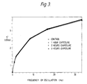
- Figs. 3, 4, 5 and 6 present graphically results obtained in tests on styrene-butadiene rubber SBR 1502 after exposing the rubber for various periods to U.V. radiation, thereby inducing gel formation in the rubber.
- the results illustrated in Fig. 3 were obtained by employing the procedure of the first step of the method of US-A-4 552 025, namely by holding a sample of the rubber at a fixed temperature (100°C) while measuring the reaction torque at a number of different oscillatory frequencies. It will be seen that the plots of frequency against S′ are not sufficiently separated to distinguish a non-irradiated sample (control) nor the samples of rubber which has been exposed to various periods of U.V. radiation from each other. In contrast, the results obtained by the method of the invention, as shown in Figs. 4, 5 and 6, distinguish clearly between the different samples.
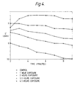
- the graph of Fig. 4 is a plot of S′ against time at a fixed temperature, (100°C) amplitude and frequency of oscillation (90° and 0.0625 Hz respectively). The results are directly comparable with those of Fig. 3, part of each sample of rubber having been used for the prior art test method and part for the method according to the invention. It will be seen from Fig. 4 that the value of S′ increases with the duration of UV exposure. The indicated value of S′ is seen to decrease slowly over the period of the test.
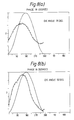
- Figs. 5 and 6 show the values 100°C and 0.0625 Hz of S′ and Tan Delta measured at a series of amplitudes on samples obtained by irradiating a different SBR 1502 from that used in the previous tests. The exposure times ranged from 0 to 3 hours. It can be seen that S′ increases and Tan delta decreases with exposure. On the graph of S′, discrimination between the various samples is adequate at an angle of 30°, but better at larger angles. When Tan delta measurements are used for distinguishing the samples, a preferred minimum angle of oscillation would be about 40°.
- Fig. 7(a) and (b) and Fig. 8(a) and (b) show how the shape of the curve of relative torque calculated from harmonic analysis plotted against phase angle varies with the amplitude of oscillation.
- the sinusoidal motion of the lower die which applies shearing force is indicated by the continuous lines.
- the amplitude of oscillation is 20°; in Figs. 7(b) and 8(b) the amplitude of oscillation is 50°.
- the data of Fig. 7(a) and (b) were derived from measurements at 100°C and 0.0625 Hz on ex-factory SBR-1502.
- Those of Fig. 8(a) and (b) were derived from measurements at 100°C and 0.0625 Hz on SBR-1502 which has been subjected to U.V. radiation for 4.5 hours.
Landscapes
- Physics & Mathematics (AREA)
- Health & Medical Sciences (AREA)
- Life Sciences & Earth Sciences (AREA)
- Chemical & Material Sciences (AREA)
- Analytical Chemistry (AREA)
- Biochemistry (AREA)
- General Health & Medical Sciences (AREA)
- General Physics & Mathematics (AREA)
- Immunology (AREA)
- Pathology (AREA)
- Investigating Strength Of Materials By Application Of Mechanical Stress (AREA)
- Vibration Prevention Devices (AREA)
- Sampling And Sample Adjustment (AREA)
Abstract
Description
- This invention relates to a method and apparatus for measuring the properties of viscoelastic materials.
- The relevant prior art includes the plastometer of Mooney described in US-A-2 037 529, and the rheometer described in GB-A-1 036 904. In each of these instruments, a sample of the material to be tested is enclosed in a cavity formed between two opposing dies, rotational shear is applied to the sample by means of a rotor embedded in the sample, and the torque required to apply the shear is measured. In the former instrument, the rotation of the rotor is continuous; in the latter the rotation is oscillatory.
- Other instruments in which an oscillatory, rotary shearing force is applied to a sample of viscoelastic material held between two opposing dies are those described in US-A-3 479 858, US-A-3 488 992, US-A-4 343 190, and US-A-4 552 025. In these instruments, the force is applied by rotation of one die relative to the other, and the measurements made are of the torque required to apply the shearing force or of the torque induced in the second die (reaction torque) when the first (driven) die is rotated.
- For the operation of prior art instruments involving an oscillatory shearing force, relatively small angles of oscillation are envisaged. This is because such instruments have been primarily intended to obtain information about the behaviour of compounded rubber stocks immediately prior to and during vulcanisation. For example, GS-A-1 036 904 mentions oscillation through a small angle, for example 2°; US-A-3 479 858 refers to reciprocal rotation through a given angle (usually not more than 15°); and US-A-4 343 190 and US-A-4 552 025 state that the rotation is preferably sinusoidal and is preferably performed through an angle of from 0.1 to 10°.
- As regards the frequency of oscillation in the prior art methods, US-A-3 681 980 mentions frequencies of up to 3,600 cycles per minute (60 Hz), with an example at 852 cycles per minute (14.2 Hz), and US-A-4 343 190 and US-A-4 552 025 mention frequencies of from 1 to 2000 cycles per minute (0.0167 to 33.33 Hz) and from 1 to 10000 cycles per minute (0.0167 to 166.67 Hz) respectively.
- A characteristic of the method of testing disclosed in US-A-4 552 025 is that a sample of viscoelastic material is held at a predetermined temperature while the force induced in reaction to the deflection of the material at two or more oscillatory frequencies is measured. The sample is then held at another, higher, predetermined temperature while the said force is measured at one or more oscillatory frequencies. The method is intended primarily to give information, derivable from the measurements at the first predetermined temperature, about the rheological behaviour of rubber compounds at typical pre-vulcanization temperatures, and information about the curing characteristics of the same compound during vulcanisation at the second, higher temperature.
- We have now found that data derivable by testing samples of viscoelastic materials which do not thermoset during the period of the test are much more discriminating in distinguishing different materials or in identifying deviations from a standard if the sample is subjected to a rotatory, oscillatory shearing force having a greater amplitude of oscillation than any disclosed or suggested by the prior art. Oscillation frequencies towards the lower end of the ranges mentioned in the above prior art documents or below are employed.
- The method of the invention is a method of testing a sample of viscoelastic material held under pressure between two opposing, temperature-controlled dies, which comprises subjecting the sample to an oscillatory, rotary shearing force having a predetermined amplitude and frequency, and measuring a torque which is indicative of the response of the sample to the shearing force, characterised in that at least one measurement of said torque is made when the said predetermined amplitude is at least ±10°, but not greater than ±360°, and said frequency is within the range 0.001 to 2 Hz.
- The apparatus of the invention comprises two opposing dies movable between an open position and a closed position, and adapted, when in the closed position, to contain between them a sample of viscoelastic material under pressure, means for controlling the temperature of the dies, means for applying an oscillatory, rotary shearing force to a sample of viscoelastic material contained between the closed dies, and means for measuring a torque which is indicative of the response of the sample to the shearing force, characterised in that the means for applying the shearing force comprise means for applying the shearing force at at least one amplitude of oscillation within the range ±10° to ±360° and a frequency of oscillation within the range 0.001 to 2 Hz.
- In preferred embodiments of the method and apparatus, the shearing force is applied to the sample by oscillatory rotation of one of the dies with respect to the other, and the torque indicative of the response of the sample to the shearing force is the reaction torque measured on the other die. Other arrangements are possible, however. For example, the force could be applied to the sample by means of a rotor embedded in the sample as in the Mooney viscometer or the rheometer described in G8-A-1 036 904; and the torque which is measured to indicate the response of the sample to the oscillatory shearing force could be the torque applied to the said one of the dies or to the rotor.
- Preferably, the said at least one amplitude of oscillation is an amplitude within the range ±10 to ±200°, and more preferably within the range ±20° to ±120°. Depending on the viscoelastic material to be tested and the data which it is desired to derive from the test, torque measurements may be made at a single amplitude of oscillation or at a series of two or more different amplitudes. In the case of measurements at single amplitude, this is preferably an amplitude within the range ±20° to ±120°, for example within the range ±40° to ±120°. In the case of measurements at a series of different amplitudes, the selected amplitudes preferably include two or more within the range ±10° to ±120°, but the series can also include measurements at smaller amplitudes, for example ±5°, or larger amplitudes. Moreover, measurements at a given amplitude can be made at a single frequency or at a number of different frequencies of oscillation; and measurements at a series of amplitudes can be made at a fixed temperature throughout, or one or more measurements can be made at one temperature and one or more at a different temperature.
- The oscillatory rotation in the method and apparatus of the invention is preferably sinusoidal. Useful parameters for characterising viscoelastic materials derivable from torque measurements under such conditions are the elastic or storage modulus S′, the viscous or loss modulus S˝ and the tangent of the loss angle (delta) which is the ratio S˝/S′. S′ can be calculated from the torque measured at the point of maximum displacement, while S˝ can be calculated from the torque at zero displacement. However, measurement of the torque at a series of sampling points throughout the oscillation can provide useful data about the sample. For example, the method of the present invention can incorporate the features of the method of US-A-4 794 788 which comprises (A) separately subjecting both a sample of the material and a standard to a sinusoidal shearing force, (B) separately measuring a material response and a standard response at at least three displacement data points equally spaced throughout a cycle of oscillation (C) separately applying a calculation operation to the data points to (i) convert the material data points into values representing either a storage modulus or a loss modulus of the material; and to (ii) convert the standard data points into values representing a standard torque and a standard phase angle, and (D) correcting the values representing the storage modulus or loss modulus for the material. As explained in US-A-4 794 788, the optimum number of data points is 16 per cycle.
- In certain instances an improved characterisation of the viscoelastic material can be achieved by subjecting the torque response to harmonic analysis. The response of the viscoelastic material at large angle deformation produces a non-sinusoidal torque envelope. The shape of the torque curve can be fully described mathematically by using Fourier transformations by means of which all the dominant sine wave frequencies and amplitudes can be determined.
- Any or all of the parameters to be used for characterising the viscoelastic elastic material can be electronically derived from the torque measurements during the course of the test and continuously displayed.
- In the preferred form of die, the opposing faces are shallow, coaxial cones disposed so that the separation of the faces increases with the radial distance from the axis. A preferred arrangement is for the lower die face to have the form of a cone and for the upper die face to be an inverted cone, the use of flat-topped cones being particularly preferred. The die faces will normally be provided with radial grooves or similar means to prevent slippage of a sample of viscoelastic material held in the die.
- In preferred embodiments of the apparatus, the lower die is driven from a computer-controlled electric motor located beneath the die and having its output shaft coaxial with and rigidly coupled to the die. The computer is programmed so that the output shaft of the motor moves at the desired angular displacement and frequency or through a sequence of desired angular displacements and frequencies. Although a sinusoidal oscillation is often preferred, the arrangement described above allows the rotary oscillation of the lower die in other modes. For example, by suitable electronic processing of torque measurements in a particular embodiment of the invention using constant oscillating speed, it is possible to derive information concerning the rheological properties of viscoelastic materials which corresponds essentially to that provided by the Mooney viscometer.
- Such a method and apparatus in fact represent an improvement over the current Mooney method because the latter suffers from drift in torque measurements which is the result of the continuous rotation of the rotor.
- The form of oscillatory motion is not limited, and can be, for example, sinusoidal, constant angular velocity, ramp, triangular or any combination of different motions.
- Fig. 1 of the drawings shows diagrammatically certain elements of an apparatus embodying the invention.
- Fig. 2 of the drawings is a vertical cross-section showing dies in the closed position. Figs. 4 to 8 represent graphically results obtained by the method of the invention, while Fig. 3 represents results obtained by a prior art method.
- Referring to Fig. 1 of the drawings, the members (1), (2) and (3) are respectively left and right vertical, and horizontal components of an outer frame which is supported on a base (not shown). A lower die assembly comprising a die housing (4) and a housing (5) for a drive shaft (6) connected at its upper end to a lower die (not shown), is mounted in the horizontal member (3). An inner frame, which is located beneath the horizontal member (3), has vertical portions (7) and (8) and a lower horizontal portion (9). Tie rods (10) and (11) which pass through the horizontal member (3) are attached at their upper ends to an upper crosshead (12) and at their lower ends to a lower crosshead (13). An upper die assembly comprising an upper die housing (14) is mounted in the upper crosshead.
- A pneumatic cylinder (15) mounted beneath the horizontal portion (9) of the inner frame has a cylinder rod (16) which is connected to the lower crosshead (13). Actuation of the pneumatic cylinder causes the assembly consisting of the cylinder rod (16), lower crosshead (13) tie rods (10) and (11) and upper crosshead (12) to travel downwards, thus bringing the upper die housing (14), the lower die housing (4) and the dies into the closed position shown in Fig. 2.
- The drive system to the lower die comprises a computer-controlled electric motor (17), for example a Compumotor stepper motor with 25,000 steps per revolution, mounted with its output shaft (18) coaxial with the drive shaft (6) to the lower die, the two shafts being coupled by means of a sleeve (19).
- In Fig. 2 of the drawings, there are illustrated parts of upper and lower die assemblies. The lower edge of the upper die housing and the upper edge of the lower die housing are indicated at (21) and (22) respectively. Other parts shown are sealing plates (23) and (24), which are attached to the edges of the die housings, upper and lower dies plates, (25) and (26) respectively, and sealing rings (27) and (28). Each die plate has a cylindrical cavity (29) adapted to accommodate a temperature probe (30). The opposing faces (31) and (32) of the die plates which define the die cavity are in the form of shallow flat-topped cones having radial grooves (33). Thus a sample in the die cavity has a thin, flat circular portion in the middle and an outer portion which increases in thickness radially outwards. The function of the channel (34) in the lower sealing plate (24) is to accommodate any overflow of the sample material which is expressed during closure of the dies.
- Parts of the upper and lower die assemblies which are not illustrated, being generally similar to those shown in Fig. 2 of US-A-4 552 025 are (in the upper assembly) a torque transducer, means connecting the upper die to the force transducer, and heating elements; and in the lower die assembly, a shaft coaxial with the lower die, means connecting the die to the shaft, a bearing housing for the shaft, and heating elements for the die.
- Figs. 3, 4, 5 and 6 present graphically results obtained in tests on styrene-butadiene rubber SBR 1502 after exposing the rubber for various periods to U.V. radiation, thereby inducing gel formation in the rubber. The results illustrated in Fig. 3 were obtained by employing the procedure of the first step of the method of US-A-4 552 025, namely by holding a sample of the rubber at a fixed temperature (100°C) while measuring the reaction torque at a number of different oscillatory frequencies. It will be seen that the plots of frequency against S′ are not sufficiently separated to distinguish a non-irradiated sample (control) nor the samples of rubber which has been exposed to various periods of U.V. radiation from each other. In contrast, the results obtained by the method of the invention, as shown in Figs. 4, 5 and 6, distinguish clearly between the different samples.
- The graph of Fig. 4 is a plot of S′ against time at a fixed temperature, (100°C) amplitude and frequency of oscillation (90° and 0.0625 Hz respectively). The results are directly comparable with those of Fig. 3, part of each sample of rubber having been used for the prior art test method and part for the method according to the invention. It will be seen from Fig. 4 that the value of S′ increases with the duration of UV exposure. The indicated value of S′ is seen to decrease slowly over the period of the test.
- Figs. 5 and 6 show the values 100°C and 0.0625 Hz of S′ and Tan Delta measured at a series of amplitudes on samples obtained by irradiating a different SBR 1502 from that used in the previous tests. The exposure times ranged from 0 to 3 hours. It can be seen that S′ increases and Tan delta decreases with exposure. On the graph of S′, discrimination between the various samples is adequate at an angle of 30°, but better at larger angles. When Tan delta measurements are used for distinguishing the samples, a preferred minimum angle of oscillation would be about 40°.
- Fig. 7(a) and (b) and Fig. 8(a) and (b) show how the shape of the curve of relative torque calculated from harmonic analysis plotted against phase angle varies with the amplitude of oscillation. The sinusoidal motion of the lower die which applies shearing force is indicated by the continuous lines. In Figs. 7(a) and 8(a), the amplitude of oscillation is 20°; in Figs. 7(b) and 8(b) the amplitude of oscillation is 50°. The data of Fig. 7(a) and (b) were derived from measurements at 100°C and 0.0625 Hz on ex-factory SBR-1502. Those of Fig. 8(a) and (b) were derived from measurements at 100°C and 0.0625 Hz on SBR-1502 which has been subjected to U.V. radiation for 4.5 hours.
Claims (13)
Applications Claiming Priority (2)
| Application Number | Priority Date | Filing Date | Title |
|---|---|---|---|
| GB8921241 | 1989-09-20 | ||
| GB898921241A GB8921241D0 (en) | 1989-09-20 | 1989-09-20 | Testing of viscoelastic materials |
Publications (3)
| Publication Number | Publication Date |
|---|---|
| EP0419440A2 true EP0419440A2 (en) | 1991-03-27 |
| EP0419440A3 EP0419440A3 (en) | 1991-09-25 |
| EP0419440B1 EP0419440B1 (en) | 1995-06-14 |
Family
ID=10663343
Family Applications (1)
| Application Number | Title | Priority Date | Filing Date |
|---|---|---|---|
| EP90870151A Expired - Lifetime EP0419440B1 (en) | 1989-09-20 | 1990-09-17 | Testing of viscoelastic materials |
Country Status (11)
| Country | Link |
|---|---|
| US (1) | US5079956A (en) |
| EP (1) | EP0419440B1 (en) |
| JP (1) | JPH03152442A (en) |
| KR (1) | KR920011037B1 (en) |
| AT (1) | ATE123873T1 (en) |
| CA (1) | CA2025692C (en) |
| DE (1) | DE69020078T2 (en) |
| DK (1) | DK0419440T3 (en) |
| ES (1) | ES2074557T3 (en) |
| GB (1) | GB8921241D0 (en) |
| GR (1) | GR3017404T3 (en) |
Cited By (2)
| Publication number | Priority date | Publication date | Assignee | Title |
|---|---|---|---|---|
| US5606115A (en) * | 1995-02-27 | 1997-02-25 | Janesko, Oy | Measures device for measuring the rheological properties of a substance |
| US8454865B2 (en) | 2007-02-06 | 2013-06-04 | Cobarr, S.P.A. | Radial mixing devices for rotating inclined reactors |
Families Citing this family (21)
| Publication number | Priority date | Publication date | Assignee | Title |
|---|---|---|---|---|
| US5163317A (en) * | 1990-03-26 | 1992-11-17 | Bridgestone Corporation | Apparatus for measuring stress of viscoelastic material |
| JPH07111022B2 (en) * | 1991-03-08 | 1995-11-29 | 株式会社島精機製作所 | Glove and glove knitting method for edge |
| GB9108961D0 (en) * | 1991-04-26 | 1991-06-12 | Monsanto Plc | Instrument and method for viscoelasticity measurements |
| JPH05126714A (en) * | 1991-10-31 | 1993-05-21 | Shimadzu Corp | Viscosity measuring device |
| JPH06123696A (en) * | 1992-10-13 | 1994-05-06 | Seiko Instr Inc | Dynamic viscoelasticity device |
| US5396804A (en) * | 1993-10-12 | 1995-03-14 | Gas Research Institute | Apparatus and method for force-controlled fatigue testing |
| US5349847A (en) * | 1993-11-29 | 1994-09-27 | Quantum Chemical Corporation | Releasable stationary plate for rheometer |
| US5569858A (en) * | 1994-05-16 | 1996-10-29 | The B. F. Goodrich Company | Viscoelastic material testing system |
| US6341531B1 (en) * | 1998-10-29 | 2002-01-29 | Pirelli Pneumatici S.P.A. | Method for improving the archiving of dynamic parameters |
| US6176005B1 (en) * | 1998-12-15 | 2001-01-23 | International Business Machines Corporation | Method of making read head with improved lead layers |
| US6164818A (en) * | 1999-01-21 | 2000-12-26 | Alpha Technologies | Method and apparatus for measuring viscous heating of viscoelastic materials |
| US6336357B1 (en) | 1999-03-15 | 2002-01-08 | Henry Pawlowski | Method and apparatus for sealing test materials |
| FR2799547B1 (en) * | 1999-10-06 | 2002-05-24 | Gradient Ass | DISC TRIBOMETER FOR MEASURING TRIBOLOGICAL PHENOMENES |
| WO2002059572A1 (en) * | 2001-01-22 | 2002-08-01 | Alpha Technologies, Us, L.P. | Viscoelastic measuring apparatus and method having a pressure regulation system for die gap compensation |
| US6575021B1 (en) * | 2002-04-10 | 2003-06-10 | Boston Rheology, Inc. | Sample surface component for an instrument that measures viscosity and viscoelasticity |
| JP4136532B2 (en) * | 2002-08-19 | 2008-08-20 | 鬼怒川ゴム工業株式会社 | Viscoelastic material processability evaluation method and apparatus, processing condition setting method and processing apparatus, and process management method |
| US7249523B2 (en) * | 2004-05-06 | 2007-07-31 | California Institute Of Technology | Apparatus and method for measuring mechanical properties |
| US20070220990A1 (en) * | 2006-03-23 | 2007-09-27 | Putman John B | Material testing apparatus with selectively sealed and unsealed dies |
| US7475592B2 (en) * | 2006-06-19 | 2009-01-13 | Alpha Technologies Services Lcc | Rheometer |
| JP4956098B2 (en) * | 2006-08-31 | 2012-06-20 | 株式会社東芝 | Deterioration diagnosis apparatus for lubricant and viscous material and deterioration diagnosis method thereof |
| US9091626B2 (en) * | 2013-03-14 | 2015-07-28 | Alpha Technologies Services Llc | Sealless rheometer die assembly |
Citations (4)
| Publication number | Priority date | Publication date | Assignee | Title |
|---|---|---|---|---|
| US3638230A (en) * | 1969-06-27 | 1972-01-25 | Japan Synthetic Rubber Co Ltd | Apparatus for measuring dynamic loss angle |
| US3681980A (en) * | 1970-08-26 | 1972-08-08 | Monsanto Co | Oscillating disk rheometer |
| DE3636872A1 (en) * | 1986-10-30 | 1988-05-11 | Messerschmitt Boelkow Blohm | Apparatus for determining gel time |
| US4794788A (en) * | 1987-10-05 | 1989-01-03 | Monsanto Company | Method and apparatus for rheological testing |
Family Cites Families (7)
| Publication number | Priority date | Publication date | Assignee | Title |
|---|---|---|---|---|
| US2037529A (en) * | 1932-08-11 | 1936-04-14 | Us Rubber Co | Plastometer |
| GB1036904A (en) * | 1962-10-18 | 1966-07-20 | Monsanto Co | Measuring apparatus for determining the properties of plastic materials |
| US3479858A (en) * | 1966-03-08 | 1969-11-25 | Japan Synthetic Rubber Co Ltd | Apparatus for measuring viscoelasticity |
| US3534594A (en) * | 1967-09-05 | 1970-10-20 | Degussa | Pressure control in a vulcanizing test chamber |
| US3488992A (en) * | 1967-09-25 | 1970-01-13 | Goodrich Co B F | Curometer |
| US4343190A (en) * | 1980-06-02 | 1982-08-10 | Monsanto Company | Moving die rheometer, method of testing materials therewith, and die for use therein |
| US4552025A (en) * | 1983-09-06 | 1985-11-12 | Monsanto Company | Multifunction processability testing method and apparatus |
-
1989
- 1989-09-20 GB GB898921241A patent/GB8921241D0/en active Pending
-
1990
- 1990-09-17 DK DK90870151.9T patent/DK0419440T3/en active
- 1990-09-17 EP EP90870151A patent/EP0419440B1/en not_active Expired - Lifetime
- 1990-09-17 AT AT90870151T patent/ATE123873T1/en not_active IP Right Cessation
- 1990-09-17 ES ES90870151T patent/ES2074557T3/en not_active Expired - Lifetime
- 1990-09-17 US US07/583,736 patent/US5079956A/en not_active Expired - Lifetime
- 1990-09-17 DE DE69020078T patent/DE69020078T2/en not_active Expired - Lifetime
- 1990-09-19 KR KR1019900014856A patent/KR920011037B1/en not_active IP Right Cessation
- 1990-09-19 CA CA002025692A patent/CA2025692C/en not_active Expired - Fee Related
- 1990-09-19 JP JP2247642A patent/JPH03152442A/en active Pending
-
1995
- 1995-09-13 GR GR950402537T patent/GR3017404T3/en unknown
Patent Citations (4)
| Publication number | Priority date | Publication date | Assignee | Title |
|---|---|---|---|---|
| US3638230A (en) * | 1969-06-27 | 1972-01-25 | Japan Synthetic Rubber Co Ltd | Apparatus for measuring dynamic loss angle |
| US3681980A (en) * | 1970-08-26 | 1972-08-08 | Monsanto Co | Oscillating disk rheometer |
| DE3636872A1 (en) * | 1986-10-30 | 1988-05-11 | Messerschmitt Boelkow Blohm | Apparatus for determining gel time |
| US4794788A (en) * | 1987-10-05 | 1989-01-03 | Monsanto Company | Method and apparatus for rheological testing |
Cited By (3)
| Publication number | Priority date | Publication date | Assignee | Title |
|---|---|---|---|---|
| US5606115A (en) * | 1995-02-27 | 1997-02-25 | Janesko, Oy | Measures device for measuring the rheological properties of a substance |
| US8454865B2 (en) | 2007-02-06 | 2013-06-04 | Cobarr, S.P.A. | Radial mixing devices for rotating inclined reactors |
| US8790580B2 (en) | 2007-02-06 | 2014-07-29 | M & G Usa Corporation | Radial mixing devices for rotating inclined reactors |
Also Published As
| Publication number | Publication date |
|---|---|
| CA2025692A1 (en) | 1991-03-21 |
| CA2025692C (en) | 1997-11-25 |
| KR920011037B1 (en) | 1992-12-26 |
| EP0419440B1 (en) | 1995-06-14 |
| ES2074557T3 (en) | 1995-09-16 |
| EP0419440A3 (en) | 1991-09-25 |
| GR3017404T3 (en) | 1995-12-31 |
| GB8921241D0 (en) | 1989-11-08 |
| ATE123873T1 (en) | 1995-06-15 |
| DK0419440T3 (en) | 1995-08-28 |
| DE69020078D1 (en) | 1995-07-20 |
| US5079956A (en) | 1992-01-14 |
| KR910006707A (en) | 1991-04-29 |
| JPH03152442A (en) | 1991-06-28 |
| DE69020078T2 (en) | 1995-11-30 |
Similar Documents
| Publication | Publication Date | Title |
|---|---|---|
| US5079956A (en) | Testing of viscoelastic materials | |
| EP0545728B1 (en) | Dynamic shear rheometer and method for its use | |
| US3803903A (en) | Apparatus and method for measuring the rheological properties of a fluid | |
| US4552025A (en) | Multifunction processability testing method and apparatus | |
| US6962086B2 (en) | Rheometer | |
| EP0227573B1 (en) | Apparatus and method for measuring rheological/viscoelastic properties of a curing rubber sample | |
| US4539838A (en) | Variable volume dual action rheometer | |
| CA1133280A (en) | Process for determining the rheometric properties of materials and apparatus for carrying out said process | |
| EP1381842B1 (en) | Fluid properties evaluation | |
| JP6771353B2 (en) | How to operate an electric motor | |
| US3982427A (en) | Apparatus for working and testing solid elastomers | |
| US6336357B1 (en) | Method and apparatus for sealing test materials | |
| EP0578127B1 (en) | Mechanical in situ curometer | |
| DE102011001412B4 (en) | Method for measuring material properties of a sample | |
| Hunston et al. | Viscoelastic characterization of structural adhesive via force oscillation experiments | |
| DE1473523C3 (en) | Method and device for measuring the theological properties of elastomeric materials | |
| Macosko et al. | Application of the Rheometrics Mechanical Spectrometer to rubber testing |
Legal Events
| Date | Code | Title | Description |
|---|---|---|---|
| PUAI | Public reference made under article 153(3) epc to a published international application that has entered the european phase |
Free format text: ORIGINAL CODE: 0009012 |
|
| AK | Designated contracting states |
Kind code of ref document: A2 Designated state(s): AT BE CH DE DK ES FR GB GR IT LI LU NL SE |
|
| PUAL | Search report despatched |
Free format text: ORIGINAL CODE: 0009013 |
|
| AK | Designated contracting states |
Kind code of ref document: A3 Designated state(s): AT BE CH DE DK ES FR GB GR IT LI LU NL SE |
|
| 17P | Request for examination filed |
Effective date: 19920215 |
|
| 17Q | First examination report despatched |
Effective date: 19931119 |
|
| GRAA | (expected) grant |
Free format text: ORIGINAL CODE: 0009210 |
|
| AK | Designated contracting states |
Kind code of ref document: B1 Designated state(s): AT BE CH DE DK ES FR GB GR IT LI LU NL SE |
|
| REF | Corresponds to: |
Ref document number: 123873 Country of ref document: AT Date of ref document: 19950615 Kind code of ref document: T |
|
| REF | Corresponds to: |
Ref document number: 69020078 Country of ref document: DE Date of ref document: 19950720 |
|
| ET | Fr: translation filed | ||
| REG | Reference to a national code |
Ref country code: DK Ref legal event code: T3 |
|
| ITF | It: translation for a ep patent filed | ||
| REG | Reference to a national code |
Ref country code: ES Ref legal event code: FG2A Ref document number: 2074557 Country of ref document: ES Kind code of ref document: T3 |
|
| PG25 | Lapsed in a contracting state [announced via postgrant information from national office to epo] |
Ref country code: LU Free format text: LAPSE BECAUSE OF NON-PAYMENT OF DUE FEES Effective date: 19950930 |
|
| REG | Reference to a national code |
Ref country code: GR Ref legal event code: FG4A Free format text: 3017404 |
|
| PLBE | No opposition filed within time limit |
Free format text: ORIGINAL CODE: 0009261 |
|
| STAA | Information on the status of an ep patent application or granted ep patent |
Free format text: STATUS: NO OPPOSITION FILED WITHIN TIME LIMIT |
|
| 26N | No opposition filed | ||
| REG | Reference to a national code |
Ref country code: CH Ref legal event code: PFA Free format text: MONSANTO P.L.C. TRANSFER- GLOBALSTRIKE PLC Ref country code: CH Ref legal event code: PUE Owner name: GLOBALSTRIKE PLC TRANSFER- SOLUTIA UK LTD |
|
| REG | Reference to a national code |
Ref country code: GB Ref legal event code: 732E |
|
| NLS | Nl: assignments of ep-patents |
Owner name: SOLUTIA UK LTD |
|
| NLT1 | Nl: modifications of names registered in virtue of documents presented to the patent office pursuant to art. 16 a, paragraph 1 |
Owner name: GLOBALSTRIKE PLC |
|
| REG | Reference to a national code |
Ref country code: FR Ref legal event code: TP |
|
| REG | Reference to a national code |
Ref country code: ES Ref legal event code: PC2A |
|
| BECA | Be: change of holder's address |
Free format text: 20001107 *SOLUTIA UK LTD:CORPORATION ROAD, NEWPORT SOUTH WALES NP9 OXF |
|
| BECH | Be: change of holder |
Free format text: 20001107 *SOLUTIA UK LTD |
|
| PGFP | Annual fee paid to national office [announced via postgrant information from national office to epo] |
Ref country code: DK Payment date: 20010615 Year of fee payment: 12 |
|
| PGFP | Annual fee paid to national office [announced via postgrant information from national office to epo] |
Ref country code: NL Payment date: 20010618 Year of fee payment: 12 |
|
| PGFP | Annual fee paid to national office [announced via postgrant information from national office to epo] |
Ref country code: GR Payment date: 20010725 Year of fee payment: 12 |
|
| PGFP | Annual fee paid to national office [announced via postgrant information from national office to epo] |
Ref country code: AT Payment date: 20010807 Year of fee payment: 12 |
|
| PGFP | Annual fee paid to national office [announced via postgrant information from national office to epo] |
Ref country code: FR Payment date: 20010831 Year of fee payment: 12 Ref country code: SE Payment date: 20010831 Year of fee payment: 12 |
|
| PGFP | Annual fee paid to national office [announced via postgrant information from national office to epo] |
Ref country code: ES Payment date: 20010919 Year of fee payment: 12 |
|
| PGFP | Annual fee paid to national office [announced via postgrant information from national office to epo] |
Ref country code: CH Payment date: 20010927 Year of fee payment: 12 |
|
| PGFP | Annual fee paid to national office [announced via postgrant information from national office to epo] |
Ref country code: BE Payment date: 20011010 Year of fee payment: 12 |
|
| REG | Reference to a national code |
Ref country code: GB Ref legal event code: IF02 |
|
| PG25 | Lapsed in a contracting state [announced via postgrant information from national office to epo] |
Ref country code: AT Free format text: LAPSE BECAUSE OF NON-PAYMENT OF DUE FEES Effective date: 20020917 |
|
| PG25 | Lapsed in a contracting state [announced via postgrant information from national office to epo] |
Ref country code: SE Free format text: LAPSE BECAUSE OF NON-PAYMENT OF DUE FEES Effective date: 20020918 Ref country code: ES Free format text: LAPSE BECAUSE OF NON-PAYMENT OF DUE FEES Effective date: 20020918 |
|
| PG25 | Lapsed in a contracting state [announced via postgrant information from national office to epo] |
Ref country code: LI Free format text: LAPSE BECAUSE OF NON-PAYMENT OF DUE FEES Effective date: 20020930 Ref country code: CH Free format text: LAPSE BECAUSE OF NON-PAYMENT OF DUE FEES Effective date: 20020930 Ref country code: DK Free format text: LAPSE BECAUSE OF NON-PAYMENT OF DUE FEES Effective date: 20020930 Ref country code: BE Free format text: LAPSE BECAUSE OF NON-PAYMENT OF DUE FEES Effective date: 20020930 |
|
| BERE | Be: lapsed |
Owner name: *SOLUTIA UK LTD Effective date: 20020930 |
|
| PG25 | Lapsed in a contracting state [announced via postgrant information from national office to epo] |
Ref country code: NL Free format text: LAPSE BECAUSE OF NON-PAYMENT OF DUE FEES Effective date: 20030401 |
|
| PG25 | Lapsed in a contracting state [announced via postgrant information from national office to epo] |
Ref country code: GR Free format text: LAPSE BECAUSE OF NON-PAYMENT OF DUE FEES Effective date: 20030404 |
|
| REG | Reference to a national code |
Ref country code: DK Ref legal event code: EBP |
|
| EUG | Se: european patent has lapsed | ||
| REG | Reference to a national code |
Ref country code: CH Ref legal event code: PL |
|
| PG25 | Lapsed in a contracting state [announced via postgrant information from national office to epo] |
Ref country code: FR Free format text: LAPSE BECAUSE OF NON-PAYMENT OF DUE FEES Effective date: 20030603 |
|
| REG | Reference to a national code |
Ref country code: FR Ref legal event code: ST |
|
| REG | Reference to a national code |
Ref country code: GB Ref legal event code: 732E |
|
| REG | Reference to a national code |
Ref country code: ES Ref legal event code: FD2A Effective date: 20031011 |
|
| PGFP | Annual fee paid to national office [announced via postgrant information from national office to epo] |
Ref country code: GB Payment date: 20090929 Year of fee payment: 20 |
|
| PGFP | Annual fee paid to national office [announced via postgrant information from national office to epo] |
Ref country code: DE Payment date: 20090929 Year of fee payment: 20 |
|
| PGFP | Annual fee paid to national office [announced via postgrant information from national office to epo] |
Ref country code: IT Payment date: 20090929 Year of fee payment: 20 |
|
| REG | Reference to a national code |
Ref country code: GB Ref legal event code: PE20 Expiry date: 20100916 |
|
| PG25 | Lapsed in a contracting state [announced via postgrant information from national office to epo] |
Ref country code: GB Free format text: LAPSE BECAUSE OF EXPIRATION OF PROTECTION Effective date: 20100916 |
|
| PG25 | Lapsed in a contracting state [announced via postgrant information from national office to epo] |
Ref country code: DE Free format text: LAPSE BECAUSE OF EXPIRATION OF PROTECTION Effective date: 20100917 |