EP0419250A2 - A construction landing platform for installation in a building under construction - Google Patents
A construction landing platform for installation in a building under construction Download PDFInfo
- Publication number
- EP0419250A2 EP0419250A2 EP90310284A EP90310284A EP0419250A2 EP 0419250 A2 EP0419250 A2 EP 0419250A2 EP 90310284 A EP90310284 A EP 90310284A EP 90310284 A EP90310284 A EP 90310284A EP 0419250 A2 EP0419250 A2 EP 0419250A2
- Authority
- EP
- European Patent Office
- Prior art keywords
- beams
- landing platform
- extending
- supported
- pair
- Prior art date
- Legal status (The legal status is an assumption and is not a legal conclusion. Google has not performed a legal analysis and makes no representation as to the accuracy of the status listed.)
- Ceased
Links
- 238000010276 construction Methods 0.000 title description 10
- 238000009434 installation Methods 0.000 title description 2
- 230000001012 protector Effects 0.000 claims description 27
- 239000000463 material Substances 0.000 description 7
- 210000003414 extremity Anatomy 0.000 description 4
- 230000004048 modification Effects 0.000 description 3
- 238000012986 modification Methods 0.000 description 3
- 230000000284 resting effect Effects 0.000 description 2
- 235000010627 Phaseolus vulgaris Nutrition 0.000 description 1
- 244000046052 Phaseolus vulgaris Species 0.000 description 1
- 229910000831 Steel Inorganic materials 0.000 description 1
- 230000000712 assembly Effects 0.000 description 1
- 238000000429 assembly Methods 0.000 description 1
- 238000009435 building construction Methods 0.000 description 1
- 239000004566 building material Substances 0.000 description 1
- 230000008878 coupling Effects 0.000 description 1
- 238000010168 coupling process Methods 0.000 description 1
- 238000005859 coupling reaction Methods 0.000 description 1
- 230000000694 effects Effects 0.000 description 1
- 239000002184 metal Substances 0.000 description 1
- 230000035939 shock Effects 0.000 description 1
- 239000010959 steel Substances 0.000 description 1
- 239000003351 stiffener Substances 0.000 description 1
- 210000001364 upper extremity Anatomy 0.000 description 1
Images


Classifications
-
- E—FIXED CONSTRUCTIONS
- E04—BUILDING
- E04G—SCAFFOLDING; FORMS; SHUTTERING; BUILDING IMPLEMENTS OR AIDS, OR THEIR USE; HANDLING BUILDING MATERIALS ON THE SITE; REPAIRING, BREAKING-UP OR OTHER WORK ON EXISTING BUILDINGS
- E04G5/00—Component parts or accessories for scaffolds
- E04G5/14—Railings
-
- E—FIXED CONSTRUCTIONS
- E04—BUILDING
- E04G—SCAFFOLDING; FORMS; SHUTTERING; BUILDING IMPLEMENTS OR AIDS, OR THEIR USE; HANDLING BUILDING MATERIALS ON THE SITE; REPAIRING, BREAKING-UP OR OTHER WORK ON EXISTING BUILDINGS
- E04G3/00—Scaffolds essentially supported by building constructions, e.g. adjustable in height
- E04G3/28—Mobile scaffolds; Scaffolds with mobile platforms
-
- E—FIXED CONSTRUCTIONS
- E04—BUILDING
- E04G—SCAFFOLDING; FORMS; SHUTTERING; BUILDING IMPLEMENTS OR AIDS, OR THEIR USE; HANDLING BUILDING MATERIALS ON THE SITE; REPAIRING, BREAKING-UP OR OTHER WORK ON EXISTING BUILDINGS
- E04G1/00—Scaffolds primarily resting on the ground
- E04G1/15—Scaffolds primarily resting on the ground essentially comprising special means for supporting or forming platforms; Platforms
-
- E—FIXED CONSTRUCTIONS
- E04—BUILDING
- E04G—SCAFFOLDING; FORMS; SHUTTERING; BUILDING IMPLEMENTS OR AIDS, OR THEIR USE; HANDLING BUILDING MATERIALS ON THE SITE; REPAIRING, BREAKING-UP OR OTHER WORK ON EXISTING BUILDINGS
- E04G21/00—Preparing, conveying, or working-up building materials or building elements in situ; Other devices or measures for constructional work
- E04G21/14—Conveying or assembling building elements
- E04G21/16—Tools or apparatus
- E04G21/166—Landings, receiving platforms
-
- E—FIXED CONSTRUCTIONS
- E04—BUILDING
- E04G—SCAFFOLDING; FORMS; SHUTTERING; BUILDING IMPLEMENTS OR AIDS, OR THEIR USE; HANDLING BUILDING MATERIALS ON THE SITE; REPAIRING, BREAKING-UP OR OTHER WORK ON EXISTING BUILDINGS
- E04G3/00—Scaffolds essentially supported by building constructions, e.g. adjustable in height
- E04G3/18—Scaffolds essentially supported by building constructions, e.g. adjustable in height supported by cantilevers or other provisions mounted in openings in the building, e.g. window openings
Definitions
- the present invention relates to loading platforms and rubbish chutes employed in the construction of buildings, particularly high rise buildings.
- loading platforms are employed to deliver and remove material from the various floors under construction.
- landing platforms are used in conjunction with the crane, which has a lift cable which delivers to or removes the material from the landing platform.
- Known landing platform have consisted of two major beams which are generally horizontal, parallel and co-extensive.
- the beams extend outwardly from a floor of the building under construction.
- the inner ends of the beams are engaged by props to secure the beams in position.
- Extending between the beams is a floor, while around the forward end of the platform there is a rail for safety purposes.
- the landing platforms have been used in conjunction with cranes placed at a remote location relative to the landing platforms. This is particularly necessary where the landing platforms are vertically aligned and the crane must have access to the forward edge of each of the platforms.
- landing platforms have suffered from the disadvantage that they are difficult to install due to their size and weight. They are also expensive to transport since they occupy considerable volume. A still further disadvantage is the requirement for several sizes of landing platforms. Accordingly, several sizes need to be manufactured and stocked.
- a still further disadvantage of known landing platforms is the limitation in respect of the loads which may be applied thereto.
- a foldable landing platform comprising: a pair of generally parallel co-extensive transversely spaced horizontal beams; a plurality of brace members extending between the beams and secured thereto; a floor panel supported on said brace members; and two side panels pivotally secured to the beams and movable from a generally upright position extending generally normal to said floor panel, and a folder transport position located adjacent said floor panel.
- a landing platform comprising: a pair of generally parallel, horizontal, co-extensive, and transversely spaced beams; a platform portion supported on said beams adjacent an end thereof; a pair of elongated prop members to extend from said beams to an overhead structure to secure the beams in position; and pivot means pivotally supporting each prop member on an associated one of the beams, each pivot means including a lateral movement support enabling movement of the prop member from a position spaced laterally of the beam, to a position spaced above the beam, and pivot means enabling pivotting of the prop member about a generally horizontal axis extending transverse of the associated beam so that the prop member can pivot from a position generally parallel to the beam, to a position extending upwardly therefrom.
- an overhead protector to be used with a crane, said protector comprising: a support frame; a generally horizontal sheet member supported on said frame and below which a vehicle or workers may be located so as to be protected thereby, an aperture in said member through which a cable may pass; and a cover extending over said aperture, said cover having a slot extending inwardly from an edge of said cover and through which a crane cable may pass, and wherein said cover is movably supported so as to follow movement of the cable.
- a landing platform comprising: a pair of generally parallel co-extensive transversely spaced horizontal beans; track means supported on and extending longitudinally of each beam; a floor panel extending between the beams and movably supported on the track means for longitudinal horizontal movement parallel to the beams from an outer position to an inner position with respect to a building which is to support the landing platform.
- the landing platform 10 consists of a pair of generally parallel co-extensive transversely spaced "I" beams 12 which are of a fabricated construction.
- Each beam 12 consists of upper and lower tubular members 13 joined by a web 14. Extending between the beams 12 are braces 15 which rest upon and are secured to the members 13 by bolts 16. Resting on the braces 15 is a floor panel 17.
- side panels 18 Secured to the beams 12 are side panels 18 which are pivotally movable from an erect operative position extending generally normal to the floor panel 17, to a folded transport position located adjacent the floor panel 17.
- the side panels 18 are directly attached to the beam 12, and more particularly the web 14.
- the side panels 18 could also be secured to the beams 12 by being pivotally mounted on the floor panel 17.
- the side panels 18 consist of panel members 19 secured to a frame 20.
- the frame 20 includes eyelets 21 which engage eyelets 22 fixed to the beam 12. Extending between the eyelets 21 and 22 are pivot pins 23. To retain the panels 18 in the upright position, bolts 24 pass through the side panels 18 and engage the member 13. It should be noted that the pivot pins 23 are spaced from the general plane of the panel 19.
- each side panel 18 is provided with a hinge assembly 25 to receive pivot pins 26 which pivotally attach doors 27 to the side panels 18.
- the side panels 18 are provided with eyelets 29 which engage pins 30 of the roof assembly 11 to secure the roof assembly 11 in position.
- the roof assembly 11 includes side panels 31, and a roof panel 32.
- the side panels 31 are pivotally attached to the roof panel 32 so as to be foldable to the transport position as best seen in Figure 8.
- the roof panel 32 is provided with a slot 33 which is reinforced, and which enables a crane cable to pass through the roof panel 32.
- the beams 12 are also provided with hooks or eyelets 34 which can be used to lift the landing platform into position.
- braces 15 and floor panels 17 may be used to vary the width of the landing platform 10. In such instances different length doors 27 would also be required as would a different length kick panel 28. Still further, the beam 12 may vary in length and dimensions to accommodate differences in working requirements such as expected weights to be received on the landing platform 10.
- the landing platform 30 consists of a pair of generally parallel co-extensive transversely spaced "I" beams 32.
- Each beam 32 consists of upper and lower flange 33 joined by a web 34.
- Extending between the beams 32 are braces 35 which rest upon and are secured to the flange 13 by bolts. Resting on the braces 35 is a floor panel 37, preferably formed of sheet metal.
- side panels 38 Secured to the beams 32 are side panels 38 which are pivotally movable from an erect operative position extending generally normal to the floor panel 37, to a folded transport position located adjacent the floor panel 37.
- the side panels 38 are directly attached to the beam 32, and more particularly the web 34 by pivots 16.
- the side panels 38 could also be secured to the beams 32 by being pivotally mounted on the floor panel 37.
- the side panels 38 consist of panel members 39 secured to a frame 40. Secured to the rear of the panels 39 are braces 41 which are bolted to the beams 32 via bottom flanges 42 secured to the bases 41.
- each side panel 38 is provided with a hinge assembly to receive pivot pins which pivotally attach doors 47 to the side panels 38.
- each beam 32 Secured to each beam 32 is a pair of prop members 43 and 44, which are pivotally movable from an erect position extending generally upwardly and normal to the beam 32, to a folded configuration located between the webs 33.
- the prop members 43 and 44 engage adjustable jacks 45 which in turn engage a floor or structure above the landing platform 30.
- the adjustable jacks apply a compressive force to the prop members 43 and 44 to secure the beams 32 in position.
- the prop members 43 and 44 are pivotally attached to their associated beams 32 by means of pivot assemblies 46 and 48.
- Each pivot assembly 46 and 48 includes a sleeve 49 through which a pivot pin 50 passes.
- the pin 50 as a stop 51 at one extremity, with the other extremity being attached to the associated prop member 43 or 44 by a radially extending flange 52.
- Each prop member 43 and 44 includes a bottom flange 53 through which bolts 54 pass to secure the prop member 43 and 44 to the flange 33.
- the pins 50 associated with the prop member 43 is located at a lower position relative to the pin 50 associated with the prop member 44. This enables the prop member 43 and 44 to be folded to positions such that the prop member 43 is located above the prop member 44 in their retracted positions. To move the prop member 43 and 44 between their folded and erected configurations, the prop members 43 and 44 need to move in a direction parallel to the pins 50.
- the prop members 43 and 44 may then pivot between a generally horizontal orientation and a
- the above described preferred embodiment of the present invention has the advantage of the platform 30 being foldable to a generally flat configuration. This facilitates stacking and transportation of the platform 30. Also by having the side panels 38 and the prop members 43 and 44 pivotally attached to the beams 32, erection of the platform 30 is relatively quick and easy.
- flanges 33 may also be advantageous to provide with "male” and “female” couplings also to facilitate stacking.
- FIGs 27 to 31 there is schematically depicted a landing platform 60 which is a modification of the platform 30 of Figures 16 to 26.
- the side panels 38 are pivotally secured to the floor panel 37 ( Figures 27 to 31).
- the floor panel 37 is attached to a pair of supports 61 which in turn are pivotally attached to the beams 32. Accordingly, the assembly of the supports 61, floor panel 37, side panels 38 and doors 47 are pivotable to a position extending generally normal to the beams 32. This particular position is illustrated in Figures 29 and 31. In this particular position, the platform 60 would then clear the way for a crane to deliver objects pass the platform 30.
- Figures 27 to 33 have the advantage of enabling a series of landing platforms to be located in vertical alignment.
- FIG. 34 to 38 there is schematically depicted an overhead protector 70.
- the overhead protector includes a series of generally parallel, horizontal and co-extensive transversely spaced beams 71.
- Prop members 72 extend upwardly from the beams 71 to secure the beams in position.
- Extending between the beams 71 are floor panels 73, while the forward edge of the overhead protector 70 is provided with an inclined edge panel 74.
- the edge panel 74 being supported by angled brackets 75 secured to the webs 76 of the beams 71.
- This particular overhead protector 70 is sufficiently strong to support scaffolding 77 directly supported thereon.
- FIG 39 there is schematically depicted a landing platform 80.
- the landing platform 80 includes a narrow portion 81 and an enlarged portion 82.
- the narrow portion 81 being dimensioned to pass between vertical uprights 83 of a scaffold assembly 84.
- the landing platform 80 would be provided with side panels 85.
- the embodiment of Figure 39 has the advantage of providing a larger landing platform that what has been traditionally available.
- FIG. 40 to 43 of the accompanying drawings there is schematically depicted a landing platform assembly 90.
- the assembly 90 is adapted to be used in construction or renovating a building 91 having floors 92.
- the floors have outer edges 93.
- the landing platform assembly 90 includes a plurality of landing platforms 93 which are vertically aligned and each consisting of a pair of generally parallel co-extensive transversely spaced "I" beams 94.
- the beams 94 have their inner ends supported on the floors 92 and if so required, may be held in position by "props".
- each pair of beams 94 Movably supported by each pair of beams 94 is a movable floor 95, which is movable between a retracted position spaced inwardly with respect to the building 91, and an outer position spaced outwardly of the floors 92.
- the horizontal beams 94 are supported by the vertical beams 96 so that the landing platform is free-standing.
- the floors thereabove are retracted so that the crane may move inwardly with respect to the building so that the material may be located above the floor which is located at its outward position.
- the above described preferred embodiment provides the advantage that a mobile crane is not required.
- the use of the crane 98 in conjunction with the movable floors 95 overcomes the need for a mobile crane.
- the overhead protector 110 includes a sheet member 111 preferably formed of steel.
- the sheet member 111 provides protection for workers and any vehicles located beneath the protector 110.
- the protector 110 includes a generally rectangular side frame 112.
- the sheet member 111 is formed with an aperture 113 through which a crane cable 114 may pass to engage or disengage an object 115 to be lifted by the crane.
- the aperture 113 extends inwardly from an edge of the sheet member 111.
- Covering the aperture 113 is a cover 116 which is movably mounted on the sheet member 111. If so required, guides or tracks may restrict movement of the cover 116 to ensure that it extends over the aperture 113.
- the cover 116 is provided with a slot 117 through which the cable 114 passes.
- the slot 117 extends inwardly from an edge of the cover 116.
- the slot 117 has an enlarged entry portion 118 to facilitate location of the cable 114 within the slot 117.
- the operator moves the cable from a remote position into the slot 117. Thereafter the object 115 is engaged or disengaged, and the cable 114 again moves from within the slot 117 to a remote position where at the cable 114 may be raised without fouling the overhead protector 110.
- the overhead protector 110 is supported on a plurality of horizontal beams 119 secured in position by means of props 120. As can be seen, the protector 110 is located at sufficient height to clear the vehicle 121.
- an opening 136 Formed in the floor panel 134 is an opening 136 covered by a removable or pivotally mounted cover plate 137. Also extending across the opening 136 is a grid 138 which may also be removable and/or pivotally mounted.
- Supported on the beams 132 are side panels 139 as well as forward gates 140.
- the chute 131 Supported on the beams 132 is the chute 131, which includes a vertically extending rubbish duct 141 which has a first pair of upper hooks 142 which engage over the side panels 139.
- the duct 141 has a second pair of hooks 143 which may be provided with projections engaged within recesses formed in the beams 142.
- Extending outwardly in a transverse direction from the duct 141 is a delivery chute 144 which extends to the opening 16 so that rubbish delivered through the opening 136 is delivered to the interior of the duct 141 via the delivery chute 144.
- the above described preferred embodiment has the advantage that the rubbish chute 131 does not require its own supporting structure but merely attaches to the landing platform 130. Still further, the rubbish chute 131 is located externally of the building thereby not hindering normal building operations and allowing final finishing of the building.
- the ends of the beams scrape along the concrete floor which is to support the platforms. This has the effect of subjecting the crane to shock loading and damaging the concrete floor.
- the extremities of the beams are provided with rollers or curved plates.
- the end portions of the beams 12, remote from the doors 27, are provided with flanges 150 which notatably support rollers 151.
- the rollers 151 are positioned so as to only engage the concrete floor when the beams 12 are inclined. During installation the beams 12 are inclined to maintain contact between the rollers 151 and the concrete floor.
Landscapes
- Engineering & Computer Science (AREA)
- Architecture (AREA)
- Mechanical Engineering (AREA)
- Civil Engineering (AREA)
- Structural Engineering (AREA)
- Conveying And Assembling Of Building Elements In Situ (AREA)
- Floor Finish (AREA)
- Refuge Islands, Traffic Blockers, Or Guard Fence (AREA)
Abstract
Description
- The present invention relates to loading platforms and rubbish chutes employed in the construction of buildings, particularly high rise buildings.
- In the construction of high rise buildings, loading platforms are employed to deliver and remove material from the various floors under construction. These landing platforms are used in conjunction with the crane, which has a lift cable which delivers to or removes the material from the landing platform.
- Known landing platform have consisted of two major beams which are generally horizontal, parallel and co-extensive. The beams extend outwardly from a floor of the building under construction. The inner ends of the beams are engaged by props to secure the beams in position. Extending between the beams is a floor, while around the forward end of the platform there is a rail for safety purposes.
- The landing platforms have been used in conjunction with cranes placed at a remote location relative to the landing platforms. This is particularly necessary where the landing platforms are vertically aligned and the crane must have access to the forward edge of each of the platforms.
- These landing platforms have suffered from the disadvantage that they are difficult to install due to their size and weight. They are also expensive to transport since they occupy considerable volume. A still further disadvantage is the requirement for several sizes of landing platforms. Accordingly, several sizes need to be manufactured and stocked.
- Traditionally the beams of the loading platforms are clamped in position by "props" which extend between the beams and an overhead structure. These props are difficult and time consuming to install.
- A still further disadvantage of known landing platforms is the limitation in respect of the loads which may be applied thereto.
- Where cranes are used on building construction sites, there is always the danger of debris and other articles falling from above. This is of particular concern in respect of the safety of the driver of a vehicle being loaded or unloaded by the crane, as well as the safety of the vehicle itself.
- During rain or high temperatures the above discussed cranes will remain idle since the vehicle being unloaded and/or loaded, is exposed together with workers which are securing to or detaching objects from the crane cable.
- In addition to the landing platforms, rubbish is removed from various floors under construction, via rubbish chutes. These chutes are separate to other requirements and are usually placed outside the building or inside cut-outs in the floor. This hinders the final finish of the building resulting in additional cost.
- It is the object of the present invention to overcome or substantially ameliorate the above disadvantages.
- There is disclosed herein a foldable landing platform comprising:
a pair of generally parallel co-extensive transversely spaced horizontal beams;
a plurality of brace members extending between the beams and secured thereto;
a floor panel supported on said brace members; and
two side panels pivotally secured to the beams and movable from a generally upright position extending generally normal to said floor panel, and a folder transport position located adjacent said floor panel. - There is further disclosed herein a landing platform comprising:
a pair of generally parallel, horizontal, co-extensive, and transversely spaced beams;
a platform portion supported on said beams adjacent an end thereof;
a pair of elongated prop members to extend from said beams to an overhead structure to secure the beams in position; and
pivot means pivotally supporting each prop member on an associated one of the beams, each pivot means including a lateral movement support enabling movement of the prop member from a position spaced laterally of the beam, to a position spaced above the beam, and pivot means enabling pivotting of the prop member about a generally horizontal axis extending transverse of the associated beam so that the prop member can pivot from a position generally parallel to the beam, to a position extending upwardly therefrom. - There is also disclosed herein a landing platform assembly comprising:
a plurality of pairs of generally parallel co-extensive transversely spaced beams, each pair to extend horizontally outward from a respective floor of a building;
a floor movably supported on each pair of beams so as to be movable relative thereto from an outer position to an inner position with respect to the building;
vertically extending beams supporting the outer extremities of the horizontal beams; and
crane means supported on the vertical beams and being operable to transfer a load from a position spaced outwardly from the vertical beams, to a position above at least one of the floors when located in its outer position with respect to the building. - There is still further disclosed herein an overhead protector to be used with a crane, said protector comprising:
a support frame;
a generally horizontal sheet member supported on said frame and below which a vehicle or workers may be located so as to be protected thereby, an aperture in said member through which a cable may pass; and
a cover extending over said aperture, said cover having a slot extending inwardly from an edge of said cover and through which a crane cable may pass, and wherein said cover is movably supported so as to follow movement of the cable. - There is also disclosed herein in combination, a landing platform and a rubbish chute; said combination comprising:
a pair of generally parallel co-extensive transversely spaced horizontal beams for attachment to a building so as to extend horizontally outwardly thereof;
a plurality of brace members extending between the beams and secured thereto;
a floor panel supported on said brace members and including an opening into which rubbish is delivered;
a vertically extending duct supported on one of said beams and located on the side of the landing platform so as to extend downwardly therefrom; and
a delivery chute extending from said opening to said duct so that rubbish delivered to said opening passes along said delivery chute to be delivered to the interior of said duct. - There is still further disclosed herein a landing platform comprising:
a pair of generally parallel co-extensive transversely spaced horizontal beans;
track means supported on and extending longitudinally of each beam;
a floor panel extending between the beams and movably supported on the track means for longitudinal horizontal movement parallel to the beams from an outer position to an inner position with respect to a building which is to support the landing platform. - A preferred forms of the present invention will now be described by way of example with reference to the accompanying drawings, wherein:
- Figure 1 is a schematic perspective view of the landing platform provided with a roof assembly;
- Figure 2 is a schematic perspective view of the landing platform of Figure 1;
- Figure 3 is a schematic perspective view of the folding platform of Figure 1 in a partly folded configuration;
- Figure 4 is a schematic end elevation of the platform of Figure 1;
- Figure 5 is a schematic end elevation of the platform of Figure 1, in a folded configuration;
- Figure 6 is a schematic perspective view of the roof assembly employed with the platform of Figure 1;
- Figure 7 is a schematic perspective view of the roof assembly of Figure 6, in a partly folded configuration;
- Figure 8 is a schematic end elevation of the roof assembly of Figure 6, in a folded configuration;
- Figure 9 is a schematic top plan view of the landing platform of Figure 1;
- Figure 10 is a schematic side elevation of the landing platform of Figure 1;
- Figure 11 is a schematic enlarged end elevation of a portion of the landing platform of Figure 1;
- Figure 12 is a schematic part exploded view of the landing platform of Figure 1;
- Figure 13 is a schematic top plan view of the roof assembly of Figure 6;
- Figure 14 is a schematic side elevation of the roof assembly of Figure 13;
- Figure 15 is a schematic end elevation of the roof assembly as seen in Figure 14;
- Figure 16 is a schematic perspective view of a landing platform;
- Figure 17 is a schematic perspective view of the landing platform of Figure 16;
- Figure 18 is a schematic perspective view of the landing platform of Figure 16 in a partly dismantled configuration;
- Figure 19 is a schematic perspective view of the landing platform of Figure 16, with securing props being secured in position;
- Figure 20 is a schematic side elevation of the upper end of the props of Figure 19;
- Figure 21 is a schematic side elevation of the lower portion of the props of Figure 19;
- Figure 22 is a schematic end elevation of the pivot assembly employed with the props illustrated in Figure 21;
- Figure 23 is a schematic side elevation of a support beam of the landing platform of Figure 16, with securing props folded thereagainst;
- Figure 24 is a schematic sectioned side elevation of the pivot assembly of Figure 22;
- Figure 25 is a schematic perspective view of the pivot assembly of Figure 24;
- Figure 26 is a schematic side elevation of the lower portion of each of the props associated with each support beam of the landing platform;
- Figure 27 is a schematic perspective view of a modification of the platform of Figure 16;
- Figure 28 is a schematic perspective view of the platform of Figure 27 in a partly folded configuration;
- Figure 29 is a schematic perspective view of the platform of Figure 27 in a further operative configuration;
- Figure 30 is a schematic side elevation of the platform as illustrated in Figure 27;
- Figure 31 is a schematic side elevation of the landing platform as shown in Figure 29;
- Figure 32 is a schematic perspective view of a still further modification of the landing platform of Figure 16;
- Figure 33 is a schematic perspective view of the landing platform of Figure 32 in an alternative motive operation;
- Figure 34 is a schematic perspective view of an overhead protector;
- Figure 35 is a schematic perspective view of the overhead protector of Figure 34, with scaffolding applied thereto;
- Figure 36 is a schematic side elevation of the protector and scaffolding of Figure 35;
- Figure 37 is a schematic side elevation of an end portion of the overhead protector of Figure 35;
- Figure 38 is a schematic part exploded perspective view of the end portion of Figure 37;
- Figure 39 is a schematic perspective view of an enlarged landing platform;
- Figure 40 is a schematic perspective view of a pre-standing landing platform;
- Figure 41 is a schematic perspective view of a modified form of the landing platform of Figure 40;
- Figure 42 is a schematic side elevation of the landing platform as illustrated in Figure 40; and
- Figure 43 is a schematic side elevation of the landing platform as illustrated in Figure 41.
- Figure 44 is a schematic perspective view of an overhead protector and crane cable used therewith;
- Figure 45 is a schematic perspective view of the protector of Figure 44;
- Figure 46 is a schematic perspective view of a construction site employing the overhead protector of Figure 44;
- Figure 47 is a schematic perspective view of an alternative support for the overhead protector of Figure 44; and
- Figure 48 is a schematic end elevation of the overhead protector of Figure 47;
- Figure 49 is a schematic perspective view of a landing platform and rubbish chute attached thereto;
- Figure 50 is a further schematic perspective view of the landing platform and rubbish chute of Figure 49;
- Figure 51 is a schematic side elevation of a series of landing platforms and rubbish chutes;
- Figure 52 is a schematic top plan view of the landing platform and rubbish chute of Figure 49.
- Figure 53 is a schematic perspective view of an end of one of the beams employed in the above landing platforms.
- In Figures 1 to 14 of the accompanying drawings there is schematically depicted a
foldable landing platform 10 which is provided with aroof assembly 11. - The
landing platform 10 consists of a pair of generally parallel co-extensive transversely spaced "I" beams 12 which are of a fabricated construction. Eachbeam 12 consists of upper and lowertubular members 13 joined by aweb 14. Extending between thebeams 12 arebraces 15 which rest upon and are secured to themembers 13 bybolts 16. Resting on thebraces 15 is afloor panel 17. - Secured to the
beams 12 areside panels 18 which are pivotally movable from an erect operative position extending generally normal to thefloor panel 17, to a folded transport position located adjacent thefloor panel 17. In this particular embodiment, theside panels 18 are directly attached to thebeam 12, and more particularly theweb 14. However it should be appreciated that theside panels 18 could also be secured to thebeams 12 by being pivotally mounted on thefloor panel 17. - As best seen in Figure 11, the
side panels 18 consist ofpanel members 19 secured to aframe 20. Theframe 20 includeseyelets 21 which engageeyelets 22 fixed to thebeam 12. Extending between theeyelets panels 18 in the upright position,bolts 24 pass through theside panels 18 and engage themember 13. It should be noted that the pivot pins 23 are spaced from the general plane of thepanel 19. - The forward end of each
side panel 18 is provided with ahinge assembly 25 to receivepivot pins 26 which pivotally attachdoors 27 to theside panels 18. - Extending between the forward ends of the
beams 12 is a kickboard 28 which inhibits material falling from the forward end of theplatform 10. - The
side panels 18 are provided witheyelets 29 which engage pins 30 of theroof assembly 11 to secure theroof assembly 11 in position. Theroof assembly 11 includesside panels 31, and aroof panel 32. Theside panels 31 are pivotally attached to theroof panel 32 so as to be foldable to the transport position as best seen in Figure 8. Theroof panel 32 is provided with aslot 33 which is reinforced, and which enables a crane cable to pass through theroof panel 32. - The
beams 12 are also provided with hooks oreyelets 34 which can be used to lift the landing platform into position. - It should be appreciated that various length braces 15 and
floor panels 17 may be used to vary the width of thelanding platform 10. In such instancesdifferent length doors 27 would also be required as would a differentlength kick panel 28. Still further, thebeam 12 may vary in length and dimensions to accommodate differences in working requirements such as expected weights to be received on thelanding platform 10. - In Figures 16 to 26 of the accompanying drawings there is schematically depicted a
landing platform 30. - The
landing platform 30 consists of a pair of generally parallel co-extensive transversely spaced "I" beams 32. Eachbeam 32 consists of upper andlower flange 33 joined by aweb 34. Extending between thebeams 32 arebraces 35 which rest upon and are secured to theflange 13 by bolts. Resting on thebraces 35 is afloor panel 37, preferably formed of sheet metal. - Secured to the
beams 32 areside panels 38 which are pivotally movable from an erect operative position extending generally normal to thefloor panel 37, to a folded transport position located adjacent thefloor panel 37. In this particular embodiment, theside panels 38 are directly attached to thebeam 32, and more particularly theweb 34 bypivots 16. However it should be appreciated that theside panels 38 could also be secured to thebeams 32 by being pivotally mounted on thefloor panel 37. - As best seen in Figure 16, the
side panels 38 consist ofpanel members 39 secured to aframe 40. Secured to the rear of thepanels 39 arebraces 41 which are bolted to thebeams 32 viabottom flanges 42 secured to thebases 41. - The forward end of each
side panel 38 is provided with a hinge assembly to receive pivot pins which pivotally attachdoors 47 to theside panels 38. - Secured to each
beam 32 is a pair ofprop members beam 32, to a folded configuration located between thewebs 33. In the operative upwardly extending position, theprop members adjustable jacks 45 which in turn engage a floor or structure above thelanding platform 30. The adjustable jacks apply a compressive force to theprop members beams 32 in position. - The
prop members beams 32 by means ofpivot assemblies pivot assembly sleeve 49 through which apivot pin 50 passes. Thepin 50 as astop 51 at one extremity, with the other extremity being attached to the associatedprop member radially extending flange 52. Eachprop member bottom flange 53 through whichbolts 54 pass to secure theprop member flange 33. Thepins 50 associated with theprop member 43 is located at a lower position relative to thepin 50 associated with theprop member 44. This enables theprop member prop member 43 is located above theprop member 44 in their retracted positions. To move theprop member prop members pins 50. Theprop members - The
side panels 38 are secured to theprop members 44 by means of bolts. This then enables theside panels 38 to act as a stiffener for thebeams 32. This in turn increases the load carrying ability of thelanding platform 30. - The above described preferred embodiment of the present invention has the advantage of the
platform 30 being foldable to a generally flat configuration. This facilitates stacking and transportation of theplatform 30. Also by having theside panels 38 and theprop members beams 32, erection of theplatform 30 is relatively quick and easy. - It may also be advantageous to provide the
flanges 33 with "male" and "female" couplings also to facilitate stacking. - In Figures 27 to 31 there is schematically depicted a
landing platform 60 which is a modification of theplatform 30 of Figures 16 to 26. In this particular embodiment, theside panels 38 are pivotally secured to the floor panel 37 (Figures 27 to 31). Also in this particular embodiment, thefloor panel 37 is attached to a pair ofsupports 61 which in turn are pivotally attached to thebeams 32. Accordingly, the assembly of thesupports 61,floor panel 37,side panels 38 anddoors 47 are pivotable to a position extending generally normal to thebeams 32. This particular position is illustrated in Figures 29 and 31. In this particular position, theplatform 60 would then clear the way for a crane to deliver objects pass theplatform 30. - As an alternative to the embodiments shown in figures 27 to 31, the
floor panel 37 could be mounted on aframe 62, best seen in Figures 32 and 33. In this particular embodiment, theframe 62 would be mounted on wheels enabling it to move in the direction of thearrow 63. Accordingly thefloor panel 37 will be movable to a retracted position again allowing a crane to move and object therepass. In this particular embodiment, theside panels 38 anddoors 47 could remain attached to thebeams 32. The wheels or rollers would engage a nail fixed to each of thebeams 32. - The embodiments of Figures 27 to 33 have the advantage of enabling a series of landing platforms to be located in vertical alignment.
- In Figures 34 to 38 there is schematically depicted an
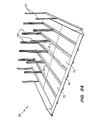
overhead protector 70. The overhead protector includes a series of generally parallel, horizontal and co-extensive transversely spaced beams 71.Prop members 72 extend upwardly from thebeams 71 to secure the beams in position. Extending between thebeams 71 arefloor panels 73, while the forward edge of theoverhead protector 70 is provided with aninclined edge panel 74. Theedge panel 74 being supported byangled brackets 75 secured to thewebs 76 of thebeams 71. This particularoverhead protector 70, is sufficiently strong to supportscaffolding 77 directly supported thereon. - In Figure 39 there is schematically depicted a
landing platform 80. Thelanding platform 80 includes anarrow portion 81 and anenlarged portion 82. Thenarrow portion 81 being dimensioned to pass betweenvertical uprights 83 of ascaffold assembly 84. Thelanding platform 80 would be provided withside panels 85. - The embodiment of Figure 39 has the advantage of providing a larger landing platform that what has been traditionally available.
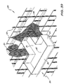
- In Figures 40 to 43 of the accompanying drawings there is schematically depicted a
landing platform assembly 90. Theassembly 90 is adapted to be used in construction or renovating a building 91 havingfloors 92. The floors haveouter edges 93. - The
landing platform assembly 90 includes a plurality oflanding platforms 93 which are vertically aligned and each consisting of a pair of generally parallel co-extensive transversely spaced "I" beams 94. Thebeams 94 have their inner ends supported on thefloors 92 and if so required, may be held in position by "props". - Movably supported by each pair of
beams 94 is amovable floor 95, which is movable between a retracted position spaced inwardly with respect to the building 91, and an outer position spaced outwardly of thefloors 92. - The
horizontal beams 94 are supported by thevertical beams 96 so that the landing platform is free-standing. - Extending across the upper extremities of the
vertical beams 96 are furtherhorizontal beams 97 which support amonorail crane assembly 98, which consists of ahorizontal rail 97 and hoist 100. - The hoist 100 may be used to transport building materials via a
materials receiving tray 101. Alternatively, the hoist 100 may be coupled to alift compartment 103. Thecompartment 103 would engage thevertical members 96 or a rail fixed thereto so that its vertical movement is governed thereby. - Attached to the
beams 94 areside panels 104 together with achute assembly 105. Thechute assembly 105 includeschute portions 106 which are vertically stacked and communicate with alower chute portion 107 through which material is delivered to abin 108. Eachchute portion 106 would have adelivery chute portion 109 which would communicate with an aperture formed in thefloor 105. The aperture would be closable via a pivotted door panel. - When material is to be delivered to one of the
floors 94, the floors thereabove are retracted so that the crane may move inwardly with respect to the building so that the material may be located above the floor which is located at its outward position. - The above described preferred embodiment provides the advantage that a mobile crane is not required. The use of the
crane 98 in conjunction with themovable floors 95 overcomes the need for a mobile crane. - In Figures 44 to 48 of the accompanying drawings there is schematically depicted an
overhead protector 110. Theoverhead protector 110 includes asheet member 111 preferably formed of steel. Thesheet member 111 provides protection for workers and any vehicles located beneath theprotector 110. Theprotector 110 includes a generallyrectangular side frame 112. - The
sheet member 111 is formed with anaperture 113 through which acrane cable 114 may pass to engage or disengage anobject 115 to be lifted by the crane. Theaperture 113 extends inwardly from an edge of thesheet member 111. - Covering the
aperture 113 is acover 116 which is movably mounted on thesheet member 111. If so required, guides or tracks may restrict movement of thecover 116 to ensure that it extends over theaperture 113. Thecover 116 is provided with aslot 117 through which thecable 114 passes. Theslot 117 extends inwardly from an edge of thecover 116. Theslot 117 has anenlarged entry portion 118 to facilitate location of thecable 114 within theslot 117. - When the
object 115 is to be coupled to or disengaged from thecable 114, the operator moves the cable from a remote position into theslot 117. Thereafter theobject 115 is engaged or disengaged, and thecable 114 again moves from within theslot 117 to a remote position where at thecable 114 may be raised without fouling theoverhead protector 110. - In Figure 46 the
overhead protector 110 is supported on a plurality ofhorizontal beams 119 secured in position by means of props 120. As can be seen, theprotector 110 is located at sufficient height to clear thevehicle 121. - In Figure 48, the
protector 110 is supported by aframe 122 consisting ofvertical members 123 andhorizontal members 124. Themembers 123 support theprotector 110 at a position enabling avehicle 125 to be located below theprotector 110. - In Figures 49 to 52 of the accompanying drawings there is schematically depicted, in combination, a
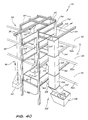
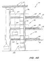
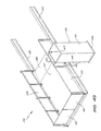
landing platform 130 and arubbish chute 131. Thelanding platform 130 includes a pair of parallel generally co-extensive horizontally extending I-beams 132 which are attached to a building and extend outwardly therefrom. Extending between thebeams 132 aresupport members 133 and afloor panel 134. Thefloor panel 134 includes aramp portion 135. - Formed in the
floor panel 134 is anopening 136 covered by a removable or pivotally mountedcover plate 137. Also extending across theopening 136 is agrid 138 which may also be removable and/or pivotally mounted. - Supported on the
beams 132 areside panels 139 as well asforward gates 140. - Supported on the
beams 132 is thechute 131, which includes a vertically extendingrubbish duct 141 which has a first pair ofupper hooks 142 which engage over theside panels 139. Theduct 141 has a second pair ofhooks 143 which may be provided with projections engaged within recesses formed in thebeams 142. Extending outwardly in a transverse direction from theduct 141 is adelivery chute 144 which extends to theopening 16 so that rubbish delivered through theopening 136 is delivered to the interior of theduct 141 via thedelivery chute 144. - The
duct 141 is provided with upper andlower flanges flanges 146 being adapted to securely engage a taperedduct portion 147 which leads to thenext duct 141 mounted on the adjacently belowlanding platform 130. This is best seen in Figure 51. - The above described preferred embodiment has the advantage that the
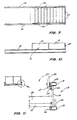
rubbish chute 131 does not require its own supporting structure but merely attaches to thelanding platform 130. Still further, therubbish chute 131 is located externally of the building thereby not hindering normal building operations and allowing final finishing of the building. - When installing landing platforms as described above, the ends of the beams (
item 12 in Fig 1) scrape along the concrete floor which is to support the platforms. This has the effect of subjecting the crane to shock loading and damaging the concrete floor. To alleviate this problem the extremities of the beams are provided with rollers or curved plates. As illustrated in Figure 52, the end portions of thebeams 12, remote from thedoors 27, are provided withflanges 150 which notatablysupport rollers 151. Therollers 151 are positioned so as to only engage the concrete floor when thebeams 12 are inclined. During installation thebeams 12 are inclined to maintain contact between therollers 151 and the concrete floor.
Claims (14)
a pair of generally parallel co-extensive transversely spaced horizontal beams 12;
a plurality of brace members 15 extending between the beams 12 and secured thereto;
a floor panel 17 supported on said brace members 15; and
two side panels 18 pivotally secured to the beams 12 and movable from a generally upright position extending generally normal to said floor panel 17, and a folder transport position located adjacent said floor panel 17.
a pair of generally parallel, horizontal, co-extensive, and transversely spaced beams 34;
a platform portion 37 supported on said beams 42 adjacent an end thereof;
a pair of elongated prop members 44 to extend from said beams to an overhead structure to secure the beams 42 in position; and
pivot means 48 pivotally supporting each prop member 44 on an associated one of the beams 42, each pivot means 48 including a lateral movement support 50 enabling movement of the prop member 44 from a position spaced laterally of the beam 42, to a position spaced above the beam 42, said pivot means 49 enabling pivotting of the prop member 44 about a generally horizontal axis extending transverse of the associated beam 42 so that the prop member 44 can pivot from a position generally parallel to the beam 42, to a position extending upwardly therefrom.
a plurality of pairs of generally parallel co-extensive transversely spaced beams 94, each pair 94 to extend horizontally outward from a respective floor 92 of a building;
a floor 95 movably supported on each pair of beams 94 so as to be movable relative thereto from an outer position to an inner position with respect to the building;
vertically extending beams 96 supporting the outer extremities of the horizontal beams 94; and
crane means 98 supported on the vertical beams 96 and being operable to a transfer a load from a position spaced outwardly from the vertical beams 96, to a position above at least one of the floors 95 when located in its outer position with respect to the building.
a support frame 119;
a generally horizontal sheet member 111 supported on said frame and below which a vehicle or workers may be located so as to be protected thereby, an aperture 113 in said member 111 through which a cable 114 may pass; and
a cover 116 extending over said aperture 113, said cover 116 having a slot 117 extending inwardly from an edge of said cover 116 and through which a crane cable 114 may pass, and wherein said cover 116 is movably supported so as to follow movement of the cable 114.
a pair of generally parallel co-extensive transversely spaced horizontal beams 132 for attachment to a building so as to extend horizontally outwardly thereof;
a plurality of brace members 133 extending between the beams 132 and secured thereto;
a floor panel 114 supported on said brace 133 and including an opening 136 into which rubbish is delivered;
a vertically extending duct 141 supported on one of said beams 132 and located on the side of the landing platform 130 so as to extend downwardly therefrom; and
a delivery chute 144 extending from said opening 136 to said duct 141 so that rubbish delivered to said opening 136 passes along said delivery chute 144 to be delivered to the interior of said duct 141.
a pair of generally parallel co-extensive transversely spaced horizontal beams 32;
track means supported on and extending longitudinally of each beam 32;
a floor panel extending between the beams 32 and movably supported on the track means for longitudinal horizontal movement parallel to the beams 32 from an outer position to an inner position with respect to a building which is to support the landing platform.
Applications Claiming Priority (10)
| Application Number | Priority Date | Filing Date | Title |
|---|---|---|---|
| AU6467/89 | 1989-09-20 | ||
| AUPJ646789 | 1989-09-20 | ||
| AU7472/89 | 1989-11-20 | ||
| AU7473/89 | 1989-11-20 | ||
| AUPJ747289 | 1989-11-20 | ||
| AUPJ747389 | 1989-11-20 | ||
| AUPJ804789 | 1989-12-29 | ||
| AU8047/89 | 1989-12-29 | ||
| AU8428/90 | 1990-02-02 | ||
| AUPJ842890 | 1990-02-02 |
Publications (2)
| Publication Number | Publication Date |
|---|---|
| EP0419250A2 true EP0419250A2 (en) | 1991-03-27 |
| EP0419250A3 EP0419250A3 (en) | 1992-02-19 |
Family
ID=27507413
Family Applications (1)
| Application Number | Title | Priority Date | Filing Date |
|---|---|---|---|
| EP19900310284 Ceased EP0419250A3 (en) | 1989-09-20 | 1990-09-20 | A landing platform and overhead protector for a construction site |
Country Status (8)
| Country | Link |
|---|---|
| EP (1) | EP0419250A3 (en) |
| JP (1) | JP2520780B2 (en) |
| KR (1) | KR910006134A (en) |
| CA (1) | CA2025886A1 (en) |
| CS (1) | CS458590A3 (en) |
| HU (1) | HUT59195A (en) |
| NO (1) | NO904116L (en) |
| NZ (1) | NZ235421A (en) |
Cited By (15)
| Publication number | Priority date | Publication date | Assignee | Title |
|---|---|---|---|---|
| ES2160001A1 (en) * | 1998-02-17 | 2001-10-16 | Perez Antonio Navarro | Portable platform for unloading construction materials. |
| GB2457236A (en) * | 2008-02-06 | 2009-08-12 | Xena Systems Ltd | Load Transportation System |
| CN102251666A (en) * | 2011-05-04 | 2011-11-23 | 河南五建第二建筑安装有限公司 | Overhanging type discharging platform |
| CN102661033A (en) * | 2012-05-14 | 2012-09-12 | 佛山市南海保达建筑机械设备有限公司 | Drawer type building receiving platform |
| CN103206076A (en) * | 2012-01-12 | 2013-07-17 | 佛山市南海保达建筑机械设备有限公司 | Movable building loading and unloading platform and moving method |
| CN103321388A (en) * | 2013-06-04 | 2013-09-25 | 张家港市盛港绿色防火建材有限公司 | Fireproof environment-friendly flue plate |
| CN105484507A (en) * | 2015-12-30 | 2016-04-13 | 佛山市南海保达建筑机械设备有限公司 | Detachable firm and safe building platform |
| US9765536B2 (en) | 2012-07-09 | 2017-09-19 | Gumboots Nominees Pty Limited | Load carrying platform shuttle |
| CN109898819A (en) * | 2019-01-29 | 2019-06-18 | 中建四局第六建筑工程有限公司 | A kind of the overhanging tool type scaffold system and its installation method of foldable telescopic |
| WO2020062968A1 (en) * | 2018-09-25 | 2020-04-02 | 上海建工集团股份有限公司 | Weatherproof steel platform system for integral steel platform formwork construction and method |
| CN112227743A (en) * | 2020-11-06 | 2021-01-15 | 四川嘉康中惠科技有限公司 | A construction hoisting platform |
| WO2021025614A1 (en) * | 2019-08-02 | 2021-02-11 | Global Engineers Investment Singapore Pte. Ltd. | A safety gate |
| CN113235897A (en) * | 2021-05-28 | 2021-08-10 | 中建八局南方建设有限公司 | A frame system that is used for connecting protection platform that encorbelments of building structure internal and external corner both sides |
| KR20230013496A (en) * | 2021-07-19 | 2023-01-26 | 망치개발 주식회사 | work plate for elevator working |
| CN117188790A (en) * | 2023-10-24 | 2023-12-08 | 中国水利水电第一工程局有限公司 | Novel movable cantilever operation platform for lock chamber construction |
Families Citing this family (3)
| Publication number | Priority date | Publication date | Assignee | Title |
|---|---|---|---|---|
| US10703591B2 (en) * | 2015-11-02 | 2020-07-07 | John Clement Preston | Loading platform |
| JP7023199B2 (en) * | 2018-08-10 | 2022-02-21 | 株式会社熊谷組 | Curing fence |
| CN110805289A (en) * | 2019-11-18 | 2020-02-18 | 广西途辉建筑工程有限公司 | Plug-in unloading platform and construction method |
Family Cites Families (5)
| Publication number | Priority date | Publication date | Assignee | Title |
|---|---|---|---|---|
| US2676066A (en) * | 1951-05-25 | 1954-04-20 | Woboril Company | Folding swing stage |
| FR1528135A (en) * | 1967-05-11 | 1968-06-07 | Receiving device, with mobile platform, used for unloading materials through an opening in a building and previously raised along the facade | |
| FR2173430A5 (en) * | 1972-02-24 | 1973-10-05 | Travaux Publics Alforien | |
| US4444289A (en) * | 1983-01-04 | 1984-04-24 | Jungman Emil A | Construction platform and method |
| US4620612A (en) * | 1983-07-31 | 1986-11-04 | Nisso Sangyo Co., Ltd. | Expansible corridor |
-
1990
- 1990-09-20 CS CS904585A patent/CS458590A3/en unknown
- 1990-09-20 EP EP19900310284 patent/EP0419250A3/en not_active Ceased
- 1990-09-20 KR KR1019900014941A patent/KR910006134A/en not_active Withdrawn
- 1990-09-20 NO NO90904116A patent/NO904116L/en unknown
- 1990-09-20 CA CA002025886A patent/CA2025886A1/en not_active Abandoned
- 1990-09-20 JP JP2251628A patent/JP2520780B2/en not_active Expired - Fee Related
- 1990-09-20 HU HU906003A patent/HUT59195A/en unknown
- 1990-09-21 NZ NZ235421A patent/NZ235421A/en unknown
Cited By (25)
| Publication number | Priority date | Publication date | Assignee | Title |
|---|---|---|---|---|
| ES2160001A1 (en) * | 1998-02-17 | 2001-10-16 | Perez Antonio Navarro | Portable platform for unloading construction materials. |
| GB2457236B (en) * | 2008-02-06 | 2012-10-10 | Xena Systems Ltd | Load transportation system |
| GB2457236A (en) * | 2008-02-06 | 2009-08-12 | Xena Systems Ltd | Load Transportation System |
| CN102251666A (en) * | 2011-05-04 | 2011-11-23 | 河南五建第二建筑安装有限公司 | Overhanging type discharging platform |
| CN102251666B (en) * | 2011-05-04 | 2012-10-10 | 河南五建第二建筑安装有限公司 | Overhanging type discharging platform |
| CN103206076B (en) * | 2012-01-12 | 2015-12-02 | 佛山市南海保达建筑机械设备有限公司 | A kind of packaged type building loading/unloading platform and moving method |
| CN103206076A (en) * | 2012-01-12 | 2013-07-17 | 佛山市南海保达建筑机械设备有限公司 | Movable building loading and unloading platform and moving method |
| CN102661033B (en) * | 2012-05-14 | 2014-08-06 | 佛山市南海保达建筑机械设备有限公司 | Drawer type building receiving platform |
| CN102661033A (en) * | 2012-05-14 | 2012-09-12 | 佛山市南海保达建筑机械设备有限公司 | Drawer type building receiving platform |
| US9765536B2 (en) | 2012-07-09 | 2017-09-19 | Gumboots Nominees Pty Limited | Load carrying platform shuttle |
| CN103321388A (en) * | 2013-06-04 | 2013-09-25 | 张家港市盛港绿色防火建材有限公司 | Fireproof environment-friendly flue plate |
| CN105484507A (en) * | 2015-12-30 | 2016-04-13 | 佛山市南海保达建筑机械设备有限公司 | Detachable firm and safe building platform |
| WO2020062968A1 (en) * | 2018-09-25 | 2020-04-02 | 上海建工集团股份有限公司 | Weatherproof steel platform system for integral steel platform formwork construction and method |
| CN109898819A (en) * | 2019-01-29 | 2019-06-18 | 中建四局第六建筑工程有限公司 | A kind of the overhanging tool type scaffold system and its installation method of foldable telescopic |
| CN109898819B (en) * | 2019-01-29 | 2023-08-18 | 中建四局第六建筑工程有限公司 | Foldable telescopic overhanging tool type scaffold system and installation method thereof |
| WO2021025614A1 (en) * | 2019-08-02 | 2021-02-11 | Global Engineers Investment Singapore Pte. Ltd. | A safety gate |
| GB2601676A (en) * | 2019-08-02 | 2022-06-08 | Global Engineers Tech Pte Ltd | A safety gate |
| ES2898123R1 (en) * | 2019-08-02 | 2022-08-02 | Global Engineers Tech Pte Ltd | Security door |
| GB2601676B (en) * | 2019-08-02 | 2023-07-12 | Global Engineers Tech Pte Ltd | A safety gate |
| US12071777B2 (en) | 2019-08-02 | 2024-08-27 | Global Engineers Technology Pte. Ltd. | Safety gate |
| CN112227743A (en) * | 2020-11-06 | 2021-01-15 | 四川嘉康中惠科技有限公司 | A construction hoisting platform |
| CN113235897A (en) * | 2021-05-28 | 2021-08-10 | 中建八局南方建设有限公司 | A frame system that is used for connecting protection platform that encorbelments of building structure internal and external corner both sides |
| KR20230013496A (en) * | 2021-07-19 | 2023-01-26 | 망치개발 주식회사 | work plate for elevator working |
| CN117188790A (en) * | 2023-10-24 | 2023-12-08 | 中国水利水电第一工程局有限公司 | Novel movable cantilever operation platform for lock chamber construction |
| CN117188790B (en) * | 2023-10-24 | 2024-04-30 | 中国水利水电第一工程局有限公司 | Novel movable cantilever operation platform for lock chamber construction |
Also Published As
| Publication number | Publication date |
|---|---|
| NZ235421A (en) | 1994-10-26 |
| HU906003D0 (en) | 1991-03-28 |
| EP0419250A3 (en) | 1992-02-19 |
| JPH03151466A (en) | 1991-06-27 |
| CA2025886A1 (en) | 1991-03-21 |
| NO904116L (en) | 1991-03-21 |
| NO904116D0 (en) | 1990-09-20 |
| HUT59195A (en) | 1992-04-28 |
| CS458590A3 (en) | 1992-02-19 |
| KR910006134A (en) | 1991-04-27 |
| JP2520780B2 (en) | 1996-07-31 |
Similar Documents
| Publication | Publication Date | Title |
|---|---|---|
| EP0419250A2 (en) | A construction landing platform for installation in a building under construction | |
| CN107013045B (en) | Loading platform | |
| US7971408B2 (en) | Stairtower and method for erecting the same | |
| PL196028B1 (en) | Partially retractable construction work working platform | |
| EP3114291B1 (en) | A container and framework elements | |
| US7258199B2 (en) | Modular multilevel access platform and method for erecting the same | |
| US7000733B2 (en) | Work platform | |
| US5394956A (en) | Suspended tender box | |
| US12071777B2 (en) | Safety gate | |
| CA2482342A1 (en) | Work platform | |
| AU748602B2 (en) | Transportable podium | |
| US6694677B2 (en) | Transportable podium | |
| AU2016102095A4 (en) | Modular gantry structure | |
| AU2004200088B2 (en) | Work platform | |
| GB2460622A (en) | A carriage for attachment to scaffolding | |
| GB2419915A (en) | Scaffold safety structures | |
| HK1241435A1 (en) | Loading platform | |
| GB2560443A (en) | Fall from heights prevention system | |
| AU4739099A (en) | A transportation platform and components thereof | |
| NZ535526A (en) | Work platform |
Legal Events
| Date | Code | Title | Description |
|---|---|---|---|
| PUAI | Public reference made under article 153(3) epc to a published international application that has entered the european phase |
Free format text: ORIGINAL CODE: 0009012 |
|
| AK | Designated contracting states |
Kind code of ref document: A2 Designated state(s): AT BE CH DE DK ES FR GB GR IT LI LU NL SE |
|
| PUAL | Search report despatched |
Free format text: ORIGINAL CODE: 0009013 |
|
| AK | Designated contracting states |
Kind code of ref document: A3 Designated state(s): AT BE CH DE DK ES FR GB GR IT LI LU NL SE |
|
| 17P | Request for examination filed |
Effective date: 19920805 |
|
| 17Q | First examination report despatched |
Effective date: 19930804 |
|
| STAA | Information on the status of an ep patent application or granted ep patent |
Free format text: STATUS: THE APPLICATION HAS BEEN REFUSED |
|
| 18R | Application refused |
Effective date: 19950218 |