EP0419086B1 - Detrimental-substance-containing theft-deterrent device - Google Patents
Detrimental-substance-containing theft-deterrent device Download PDFInfo
- Publication number
- EP0419086B1 EP0419086B1 EP90309650A EP90309650A EP0419086B1 EP 0419086 B1 EP0419086 B1 EP 0419086B1 EP 90309650 A EP90309650 A EP 90309650A EP 90309650 A EP90309650 A EP 90309650A EP 0419086 B1 EP0419086 B1 EP 0419086B1
- Authority
- EP
- European Patent Office
- Prior art keywords
- components
- pinhead
- article
- vial
- component
- Prior art date
- Legal status (The legal status is an assumption and is not a legal conclusion. Google has not performed a legal analysis and makes no representation as to the accuracy of the status listed.)
- Expired - Lifetime
Links
Images


Classifications
-
- E—FIXED CONSTRUCTIONS
- E05—LOCKS; KEYS; WINDOW OR DOOR FITTINGS; SAFES
- E05B—LOCKS; ACCESSORIES THEREFOR; HANDCUFFS
- E05B73/00—Devices for locking portable objects against unauthorised removal; Miscellaneous locking devices
- E05B73/0017—Anti-theft devices, e.g. tags or monitors, fixed to articles, e.g. clothes, and to be removed at the check-out of shops
-
- G—PHYSICS
- G08—SIGNALLING
- G08B—SIGNALLING SYSTEMS, e.g. PERSONAL CALLING SYSTEMS; ORDER TELEGRAPHS; ALARM SYSTEMS
- G08B15/00—Identifying, scaring or incapacitating burglars, thieves or intruders, e.g. by explosives
- G08B15/02—Identifying, scaring or incapacitating burglars, thieves or intruders, e.g. by explosives with smoke, gas, or coloured or odorous powder or liquid
-
- E—FIXED CONSTRUCTIONS
- E05—LOCKS; KEYS; WINDOW OR DOOR FITTINGS; SAFES
- E05B—LOCKS; ACCESSORIES THEREFOR; HANDCUFFS
- E05B39/00—Locks giving indication of authorised or unauthorised unlocking
- E05B39/002—Locks giving indication of authorised or unauthorised unlocking by releasing a liquid, e.g. ill-smelling or dye
-
- Y—GENERAL TAGGING OF NEW TECHNOLOGICAL DEVELOPMENTS; GENERAL TAGGING OF CROSS-SECTIONAL TECHNOLOGIES SPANNING OVER SEVERAL SECTIONS OF THE IPC; TECHNICAL SUBJECTS COVERED BY FORMER USPC CROSS-REFERENCE ART COLLECTIONS [XRACs] AND DIGESTS
- Y10—TECHNICAL SUBJECTS COVERED BY FORMER USPC
- Y10T—TECHNICAL SUBJECTS COVERED BY FORMER US CLASSIFICATION
- Y10T24/00—Buckles, buttons, clasps, etc.
- Y10T24/50—Readily interlocking, two-part fastener requiring either destructive or tool disengagement
-
- Y—GENERAL TAGGING OF NEW TECHNOLOGICAL DEVELOPMENTS; GENERAL TAGGING OF CROSS-SECTIONAL TECHNOLOGIES SPANNING OVER SEVERAL SECTIONS OF THE IPC; TECHNICAL SUBJECTS COVERED BY FORMER USPC CROSS-REFERENCE ART COLLECTIONS [XRACs] AND DIGESTS
- Y10—TECHNICAL SUBJECTS COVERED BY FORMER USPC
- Y10T—TECHNICAL SUBJECTS COVERED BY FORMER US CLASSIFICATION
- Y10T70/00—Locks
- Y10T70/50—Special application
- Y10T70/5004—For antitheft signaling device on protected article
Definitions
- the present invention is generally directed to devices that may be attached to articles, such as merchandise, for deterring the theft of such articles, and is particularly directed to improvements in a theft-deterrent device of the type that contains a detrimental substance that damages a protected article attached to the device by releasing such substance when the device is tampered with during an unauthorized attempt to remove the device from the article.
- the device includes means for attaching the device to the article, with the attaching means being embodied in two components that are adapted to be locked together on opposite sides of a portion of said article to prevent unauthorized removal of the device from the article.
- a typical attaching means includes a pin embodied in one of the two components and means embodied in the other component for receiving the pin. The device is attached to the protected article by passing the pin through a portion of the article.
- At least one of the two components includes a fragile elongated vial that fractures when flexed longitudinally, with said vial containing the detrimental substance that would damage the article if the vial were to be fractured while the device was attached to the article.
- a detrimental substance is contained in two frangible vials that are respectively disposed in two opposing components that are secured together on opposite sides of a portion of the protected article when the device is locked to the article.
- the vials fracture when severely contacted by a tool, such as a screw driver, that typically would be used in an attempt to pry apart the opposing components of the device so that the device could be removed from the protected article.
- the vials are so disposed in the device as to be readily contacted by a tool being used to pry apart the object and thereby fracture to release the detrimental substance onto an protected article locked to the device.
- the frangible vials are longitudinally disposed in the two opposing elongated components so that when either component is flexed longitudinally during an attempt to pry the two components apart, the vial contained therein fractures to release the detrimental substance onto an protected article locked to the device.
- the present invention provides a detrimental-substance-containing theft-deterrent device having a vial that will fracture to release the detrimental substance whenever a forceful attempt is made to detach the theft-deterrent device from the article to be protected, but which will not fracture under normal handling of the device.
- the theft-deterrent device of the present invention includes means for attaching the device to an article to be protected, with said attaching means being embodied in two components that are adapted to be locked together on opposite sides of a portion of said article to prevent unauthorized removal of the device from the article; with the attaching means including a pin having a head that is anchored within one component and a clutch contained in the other component for grasping the pin to provide a predetermined retaining force for resisting separation of the components by prying or pulling the components apart; wherein said one component includes at least one fragile elongated vial that fractures when at least a predetermined pressure is applied thereto with said vial containing a detrimental substance that would damage the article if the vial were to be fractured while the device was attached to the article; and wherein said one component defines a head space for enabling limited axial movement of the pinhead, and a guide channel for containing a movable object between the pinhead and the vial; and a movable object, such as a ball, disposed in
- the pinhead is equally supported by each of the movable objects when the pinhead is being moved in response to application to the two components of a separation force to thereby prevent the pinhead from slipping around one of said movable objects.
- the device contain flexible cradles for shielding the vials from contact with the movable objects during said relaxed state, but which yield to enable the movable objects to contact the vials when the movable objects are moved in response to the pinhead being moved in response to application to the two components of at least said predetermined threshold separation force.
- Figure 1 is an exploded perspective view of a preferred embodiment of the theft-deterrent device of the present invention.
- Figure 2 illustrates the attachment of the theft-deterrent device of Figure 1 to a protected article or clothing.
- Figure 3 is a top plan view of a member of the one component of the theft-deterrent device of Figure 1 that contains the vials and the movable objects, and anchors the pin.
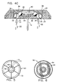
- Figures 4A, 4B and 4C are sector sectional views of the one component of the theft-deterrent device of Figure 1 that contains the vials and the movable objects, taken along lines 4-4 in Figure 3. showing a sequence of operation as the movable objects therein move to fracture the vials in response to the pin being forced downward.
- Figure 5 is a top plan view of the barrel of the second component of the theft-deterrent device of Figure 1.
- Figure 6 is a bottom plan view of the cover of the second component of the theft-deterrent device of Figure 1.
- a preferred embodiment of the theft-deterrent device of the present invention includes a first component 10 and a second component 12.
- the first component 10 includes a pin 14, and the second component 12 includes a clutch 16 for grasping the pin 14.
- the pin 14 is centrally located in the first component 10: and the clutch 16 is centrally located in the second component 12.
- the theft-deterrent device is attached to an article 18 to be protected (as illustrated in Figure 2) by passing the pin 14 through a portion of the protected article 18 and engaging the pin 14 in the clutch 16 so that the clutch 16 grasps the pin 14.
- the pin 14 has a head 40 that is anchored within the first component 10; and the clutch 16 in the second component 12 grasps the pin 14 to provide a predetermined retaining force, such as 100 pounds (25 newtons), for resisting separation of the components 10, 12 by prying or pulling the components apart.
- the predetermined retaining force must be much greater than the separation force that would be applied in attempting to separate the two components 10, 12 by using one's bare hands.
- the first component 10 includes a member 24 that contains three fragile elongated glass vials 20 that fracture when at least a predetermined pressure is applied thereto.
- Each vial 20 contains a detrimental substance 22 that would damage the protected article 18 if the vial were to be fractured while the theft-deterrent device was attached to the article 18.
- the detrimental substance 22 preferably is a fluid colored dye or permanent ink.
- the first component 10 includes a plastic vial-containing member 24 and a plastic cover 38.
- the member 24 is ultrasonically welded to the cover 38 at the circumferential edge of the member 24.
- the member 24 and the cover 38 define a head space 25 in which the pinhead 40 is anchored.
- the head space 25 also enables limited axial movement of the pinhead 40.
- the pin 14 passes through a hole 41 in the member 24.
- the member 24 further defines three chambers 26 for containing the three vials 20, and three guide channels 27 that respectively contain three stainless steel balls 29 between the pinhead 40 and the three vials 20.
- the balls 29 exert little or no pressure between the vials 20 and the pinhead 40 while the attached pin 14 and clutch 16 are in a relaxed state, which occurs when no force is being applied to separate the two components 10, 12.
- the guide channels 27 are contoured for enabling the pinhead 40 to force the balls 29 to move and apply more than said predetermined pressure against the vials 20 in response to the pinhead being moved in response to application to the two components 10, 12 of at least a predetermined threshold separation force.
- a predetermined threshold separation force such as approximately 40 pounds (10 newtons), that is nevertheless less than that required to overcome the predetermined retaining force, to thereby fracture at least one of the vials 20 to release the substance 22 contained therein before the components 10, 12 are separated by prying or pulling the components apart.
- the predetermined threshold separation force must be well above both normal handling forces for the theft-deterrent device and the separation force that would be applied in attempting to separate the two components 10. 12 by using one's bare hands: and but yet. the predetermined threshold separation force must be easily attained by attempting to pry the two components 10, 12 apart with a screwdriver.
- the vials 20 and the guide channels 27 are symmetrically disposed in relation to the pinhead 40 so that the pinhead 40 is equally supported by each of the three balls 29 when the pinhead 40 is being moved in response to application to the two components 10. 12 of a separation force, to thereby prevent the pin-head 40 from slipping around one of the balls 29.
- the first component 10 is so structured as not to flex when an attempt is made to pry the first component 10 from the second component 12 while the two components are locked together.
- Flexible nylon cradles 34 shield the vials 20 from contact with the balls 29 during said relaxed state. but yield to enable the balls 29 to contact the vials 20 when the balls 29 are moved in response to the pinhead 40 being moved in response to application to the two components 10, 12 of at least the predetermined threshold separation force.
- the purpose of such separation in the relaxed state is to assure that no ball 29 contacts any vial 20 during the ultrasonic welding stage of manufacture. If such contact were allowed during the welding stage, the vials 20 would fracture due vibrating contact with the balls 29 since the ultrasonic welding causes the balls 29 to vibrate.
- the cradles 34 also serve as shock absorbers for the vials 20 in order to prevent the vials 20 from being broken during normal handling of the theft-deterrent device.
- the pin 14 When forced separation of the two components 10. 12 is attempted, the pin 14 is forced to move axially within the vial-containing member 24 and the pin-head 40 contacts the three balls 29.
- the sequence of events that occur when the pin 14 starts moving from the point at which the pinhead 40 touches the cover 38 is illustrated in Figures 4A, 4B and 4C.
- the pinhead 40 touches the balls 29.
- the pressure point on the balls 29 at which the pinhead 40 initially contacts the balls 29. as shown in Figure 4A is at a point approximately one-fourth the lateral diameter of each ball 29.
- the force applied to the balls 29 by movement of the pinhead 40 is translated to two parts, an axial component parallel to the axial movement of the pinhead 40 and a lateral component normal to the axial movement of the pinhead 40.
- the balls 29 are restrained by the guide channels 27 to move laterally as the pin 14 moves axially; and the balls 29 initially contact the flexible nylon cradles 34, as shown in Figure 4A.
- the cradles 34 offer only light resistance to the lateral movement of the balls 29 and are flexed aside to enable the balls 29 to continue to travel laterally until the balls 29 touch the vials 20. as shown in Figure 4B.
- Further movement of the balls 29 forces the vials 20 against the walls of the chambers 26.
- Still further movement of the balls 29 drives the balls 29 into the surfaces of the vials 20 and exerts increasing pressure on the vials 20 until one or more of the three vials 20 fractures and releases the detrimental substance 22 contained therein, as shown in Figure 4C.
- the openings 31 to the chambers 26 in the exposed surface 36 of the member 24 are smaller than the vials 20 so as to recess the vials 20 from the exposed surface 36 and thereby prevent the vials 20 from being fractured during normal handling.
- the second component 12 also is so structured as not to flex when an attempt is made to pry the first component 10 from the second component 12 while the two components are locked together. thereby concentrating separation forces resulting from said prying to be applied to forcing movement of the pinhead 40 within the member 24 of the first component 10.
- the second component 12 includes a plastic cover 58 and a plastic barrel 60.
- the barrel 60 includes a central chamber 62 that holds the housing of the clutch 16.
- the concealed surface 64 of the cover 58 includes a plurality of circular stiffening ribs 66; and the barrel 60 includes a plurality of supporting struts 68 extending radially between the central chamber 62 and the outer wall 70 of the barrel 60.
- the second component 12 also includes deflection plates 72 made of two-percent-carbon hardened spring steel, which line the central chamber 62 around the clutch 16 for deflecting the bit of a drill that one might use in an attempt to penetrate the housing of the clutch 16, and thereby shield the housing of the clutch 16 from a drilling tool.
- deflection plates 72 made of two-percent-carbon hardened spring steel, which line the central chamber 62 around the clutch 16 for deflecting the bit of a drill that one might use in an attempt to penetrate the housing of the clutch 16, and thereby shield the housing of the clutch 16 from a drilling tool.
- the barrel 60 is ultrasonically welded to the cover 58 at the circumferential edge of the cover 58 and at the upper edge of the central chamber 62.
Landscapes
- Physics & Mathematics (AREA)
- General Physics & Mathematics (AREA)
- Burglar Alarm Systems (AREA)
- Road Signs Or Road Markings (AREA)
- Materials For Medical Uses (AREA)
- Packaging For Recording Disks (AREA)
- Absorbent Articles And Supports Therefor (AREA)
- Processing Of Solid Wastes (AREA)
Abstract
Description
- The present invention is generally directed to devices that may be attached to articles, such as merchandise, for deterring the theft of such articles, and is particularly directed to improvements in a theft-deterrent device of the type that contains a detrimental substance that damages a protected article attached to the device by releasing such substance when the device is tampered with during an unauthorized attempt to remove the device from the article.
- Typically, the device includes means for attaching the device to the article, with the attaching means being embodied in two components that are adapted to be locked together on opposite sides of a portion of said article to prevent unauthorized removal of the device from the article. A typical attaching means includes a pin embodied in one of the two components and means embodied in the other component for receiving the pin. The device is attached to the protected article by passing the pin through a portion of the article. At least one of the two components includes a fragile elongated vial that fractures when flexed longitudinally, with said vial containing the detrimental substance that would damage the article if the vial were to be fractured while the device was attached to the article.
- Prior art devices of this nature are described in United States Patents Nos. 4,483,049 to Gustavsson et al., 4,670,950 to Wisecup et al. and 4,649,397 to Heaton et al. Typically, these devices are used to discourage the theft of such articles of merchandise as clothing, and the detrimental substance typically is an ink or dye or foul-smelling substance that permanently stains and or fouls the clothing so as to make the clothing unattractive and thereby generally unfit for wear.
- In both the device described in U.S. Patent No. 4,483,049 and the device described in U.S. Patent No. 4,670,950, a detrimental substance is contained in two frangible vials that are respectively disposed in two opposing components that are secured together on opposite sides of a portion of the protected article when the device is locked to the article.
- In the device described in U.S. Patent No. 4,483,049, the vials fracture when severely contacted by a tool, such as a screw driver, that typically would be used in an attempt to pry apart the opposing components of the device so that the device could be removed from the protected article. The vials are so disposed in the device as to be readily contacted by a tool being used to pry apart the object and thereby fracture to release the detrimental substance onto an protected article locked to the device.
- In the device described in U.S. Patent No. 4,670,950, the frangible vials are longitudinally disposed in the two opposing elongated components so that when either component is flexed longitudinally during an attempt to pry the two components apart, the vial contained therein fractures to release the detrimental substance onto an protected article locked to the device.
- In the device described in U.S. Patent No. 4,649,397, two frangible vials are longitudinally disposed in one of two opposing elongated components so that when such component is flexed longitudinally during an attempt to pry the two components apart, the vials contained therein fracture to release the detrimental substance onto an protected article locked to the device. Such device further contains an electronic article surveillance tag of the type described in U.S. Patent No. 4,481,428 to Lincoln H. Charlot, Jr.
- The present invention provides a detrimental-substance-containing theft-deterrent device having a vial that will fracture to release the detrimental substance whenever a forceful attempt is made to detach the theft-deterrent device from the article to be protected, but which will not fracture under normal handling of the device.
- The theft-deterrent device of the present invention includes means for attaching the device to an article to be protected, with said attaching means being embodied in two components that are adapted to be locked together on opposite sides of a portion of said article to prevent unauthorized removal of the device from the article; with the attaching means including a pin having a head that is anchored within one component and a clutch contained in the other component for grasping the pin to provide a predetermined retaining force for resisting separation of the components by prying or pulling the components apart; wherein said one component includes at least one fragile elongated vial that fractures when at least a predetermined pressure is applied thereto with said vial containing a detrimental substance that would damage the article if the vial were to be fractured while the device was attached to the article; and wherein said one component defines a head space for enabling limited axial movement of the pinhead, and a guide channel for containing a movable object between the pinhead and the vial; and a movable object, such as a ball, disposed in said guide channel, with said movable object exerting little or no pressure between the vial and the pinhead while the attaching means is in a relaxed state, which occurs when no force is being applied to separate the two components; wherein the guide channel is contoured for enabling the pinhead to force the movable object to move and apply more than said predetermined pressure against the vial in response to the pinhead being moved in response to application to the two components of at least a predetermined threshold separation force that is nevertheless less than that required to overcome said predetermined retaining force, to thereby fracture the vial to release the substance contained therein before the components are separated by prying or pulling the components apart.
- Preferably there are a plurality of said vials and a corresponding number of said guide channels and movable objects symmetrically disposed in relation to said pinhead so that the pinhead is equally supported by each of the movable objects when the pinhead is being moved in response to application to the two components of a separation force to thereby prevent the pinhead from slipping around one of said movable objects.
- It is also preferable that the device contain flexible cradles for shielding the vials from contact with the movable objects during said relaxed state, but which yield to enable the movable objects to contact the vials when the movable objects are moved in response to the pinhead being moved in response to application to the two components of at least said predetermined threshold separation force.
- Additional features of the present invention are described in relation to the description of the preferred embodiment.
- Figure 1 is an exploded perspective view of a preferred embodiment of the theft-deterrent device of the present invention.
- Figure 2 illustrates the attachment of the theft-deterrent device of Figure 1 to a protected article or clothing.
- Figure 3 is a top plan view of a member of the one component of the theft-deterrent device of Figure 1 that contains the vials and the movable objects, and anchors the pin.
- Figures 4A, 4B and 4C are sector sectional views of the one component of the theft-deterrent device of Figure 1 that contains the vials and the movable objects, taken along lines 4-4 in Figure 3. showing a sequence of operation as the movable objects therein move to fracture the vials in response to the pin being forced downward.
- Figure 5 is a top plan view of the barrel of the second component of the theft-deterrent device of Figure 1.
- Figure 6 is a bottom plan view of the cover of the second component of the theft-deterrent device of Figure 1.
- Referring to Figure 1, a preferred embodiment of the theft-deterrent device of the present invention includes a
first component 10 and asecond component 12. Thefirst component 10 includes apin 14, and thesecond component 12 includes aclutch 16 for grasping thepin 14. Thepin 14 is centrally located in the first component 10: and theclutch 16 is centrally located in thesecond component 12. The theft-deterrent device is attached to anarticle 18 to be protected (as illustrated in Figure 2) by passing thepin 14 through a portion of the protectedarticle 18 and engaging thepin 14 in theclutch 16 so that theclutch 16 grasps thepin 14. While theclutch 16 is grasping thepin 14, thefirst component 10 and thesecond component 12 are locked together on opposite sides of a portion of the protectedarticle 18 and thereby prevent unauthorized removal of the theft-deterrent device from the protectedarticle 18. Thepin 14 has ahead 40 that is anchored within thefirst component 10; and theclutch 16 in thesecond component 12 grasps thepin 14 to provide a predetermined retaining force, such as 100 pounds (25 newtons), for resisting separation of thecomponents components - The
pin 14, theclutch 16 and the technique of releasing thepin 14 from the grasp of theclutch 16 so that thefirst component 10 can be unlocked from thesecond component 12 to thereby detach the protectedarticle 18 from the theft-deterrent device are described in U.S. Patent No. 4,523,356 to Lincoln H. Charlot, Jr. - Referring to Figures 1, 3 4A, 4B and 4C, the
first component 10 includes amember 24 that contains three fragileelongated glass vials 20 that fracture when at least a predetermined pressure is applied thereto. Eachvial 20 contains adetrimental substance 22 that would damage the protectedarticle 18 if the vial were to be fractured while the theft-deterrent device was attached to thearticle 18. Thedetrimental substance 22 preferably is a fluid colored dye or permanent ink. - The
first component 10 includes a plastic vial-containingmember 24 and aplastic cover 38. Themember 24 is ultrasonically welded to thecover 38 at the circumferential edge of themember 24. - The
member 24 and thecover 38 define ahead space 25 in which thepinhead 40 is anchored. Thehead space 25 also enables limited axial movement of thepinhead 40. Thepin 14 passes through a hole 41 in themember 24. - The
member 24 further defines threechambers 26 for containing the threevials 20, and threeguide channels 27 that respectively contain threestainless steel balls 29 between thepinhead 40 and the threevials 20. - The
balls 29 exert little or no pressure between thevials 20 and thepinhead 40 while the attachedpin 14 andclutch 16 are in a relaxed state, which occurs when no force is being applied to separate the twocomponents - The
guide channels 27 are contoured for enabling thepinhead 40 to force theballs 29 to move and apply more than said predetermined pressure against thevials 20 in response to the pinhead being moved in response to application to the twocomponents vials 20 to release thesubstance 22 contained therein before thecomponents components 10. 12 by using one's bare hands: and but yet. the predetermined threshold separation force must be easily attained by attempting to pry the twocomponents - The
vials 20 and theguide channels 27 are symmetrically disposed in relation to thepinhead 40 so that thepinhead 40 is equally supported by each of the threeballs 29 when thepinhead 40 is being moved in response to application to the twocomponents 10. 12 of a separation force, to thereby prevent the pin-head 40 from slipping around one of theballs 29. To further prevent any such slippage thefirst component 10 is so structured as not to flex when an attempt is made to pry thefirst component 10 from thesecond component 12 while the two components are locked together. -
Flexible nylon cradles 34 shield thevials 20 from contact with theballs 29 during said relaxed state. but yield to enable theballs 29 to contact thevials 20 when theballs 29 are moved in response to thepinhead 40 being moved in response to application to the twocomponents ball 29 contacts anyvial 20 during the ultrasonic welding stage of manufacture. If such contact were allowed during the welding stage, thevials 20 would fracture due vibrating contact with theballs 29 since the ultrasonic welding causes theballs 29 to vibrate. - The
cradles 34 also serve as shock absorbers for thevials 20 in order to prevent thevials 20 from being broken during normal handling of the theft-deterrent device. - When forced separation of the two
components 10. 12 is attempted, thepin 14 is forced to move axially within the vial-containingmember 24 and the pin-head 40 contacts the threeballs 29. The sequence of events that occur when thepin 14 starts moving from the point at which thepinhead 40 touches thecover 38 is illustrated in Figures 4A, 4B and 4C. Thepinhead 40 touches theballs 29. The pressure point on theballs 29 at which thepinhead 40 initially contacts theballs 29. as shown in Figure 4A, is at a point approximately one-fourth the lateral diameter of eachball 29. The force applied to theballs 29 by movement of thepinhead 40 is translated to two parts, an axial component parallel to the axial movement of thepinhead 40 and a lateral component normal to the axial movement of thepinhead 40. Theballs 29 are restrained by theguide channels 27 to move laterally as thepin 14 moves axially; and theballs 29 initially contact the flexible nylon cradles 34, as shown in Figure 4A. Thecradles 34 offer only light resistance to the lateral movement of theballs 29 and are flexed aside to enable theballs 29 to continue to travel laterally until theballs 29 touch thevials 20. as shown in Figure 4B. Further movement of theballs 29 forces thevials 20 against the walls of thechambers 26. Still further movement of theballs 29 drives theballs 29 into the surfaces of thevials 20 and exerts increasing pressure on thevials 20 until one or more of the threevials 20 fractures and releases thedetrimental substance 22 contained therein, as shown in Figure 4C. At this point the lateral pressure on theother vials 20 by theballs 29 is relaxed, thereby allowing thepinhead 40 to slip around theballs 29, whereby the other vials will probably not rupture. Direct pull tests conducted when the axial orientation of thepin 14 is maintained within the vial-containingmember 24 after thefirst vial 20 has ruptured shows theother vials 20 will probably also rupture. But when attempts were made to separate the twocomponents first vial 20 fractures is sufficient to deform the vial-containingmember 24 at the pinhole 41, thereby allowing thepinhead 40 to slip around the other twoballs 29. thus leaving the other twovials 20 in tact. - The
openings 31 to thechambers 26 in the exposedsurface 36 of themember 24 are smaller than thevials 20 so as to recess thevials 20 from the exposedsurface 36 and thereby prevent thevials 20 from being fractured during normal handling. - The
second component 12 also is so structured as not to flex when an attempt is made to pry thefirst component 10 from thesecond component 12 while the two components are locked together. thereby concentrating separation forces resulting from said prying to be applied to forcing movement of thepinhead 40 within themember 24 of thefirst component 10. - Referring to Figures 5 and 6, the
second component 12 includes aplastic cover 58 and aplastic barrel 60. Thebarrel 60 includes acentral chamber 62 that holds the housing of the clutch 16. In order to make thesecond component 12 rigid so that it does not flex. theconcealed surface 64 of thecover 58 includes a plurality ofcircular stiffening ribs 66; and thebarrel 60 includes a plurality of supportingstruts 68 extending radially between thecentral chamber 62 and theouter wall 70 of thebarrel 60. - The
second component 12 also includesdeflection plates 72 made of two-percent-carbon hardened spring steel, which line thecentral chamber 62 around the clutch 16 for deflecting the bit of a drill that one might use in an attempt to penetrate the housing of the clutch 16, and thereby shield the housing of the clutch 16 from a drilling tool. - The
barrel 60 is ultrasonically welded to thecover 58 at the circumferential edge of thecover 58 and at the upper edge of thecentral chamber 62.
Claims (13)
- A device for deterring theft of a protected article, comprising
means for attaching the device to the article, with said attaching means being embodied in two components (10, 12) that are adapted to be locked together on opposite sides of a portion of said article to prevent unauthorized removal of the device from the article, wherein the attaching means include a pin (14) having a head (40) that is anchored within one component (10) and a clutch (16) contained in the other component (12) for grasping the pin to provide a predetermined retaining force for resisting separation of the components by prying or pulling the components apart;
wherein said one component (10) includes at least one fragile elongated vial (20) that fractures when at least a predetermined pressure is applied thereto, with said vial containing a detrimental substance (22) that would damage the article if the vial were to be fractured while the device was attached to the article;
charaterized in that:
said one component defines a head space (25) for enabling limited axial movement of the pinhead (40) and a guide channel (27) for containing a movable object (29) between the pinhead and the vial (20);
a movable object (29) is disposed in said guide channel (27), with said movable object exerting little or no pressure between the vial (20) and the pinhead (40) while the attaching means (14, 16) is in a relaxed state, which occurs when no force is being applied to separate the two components (10, 12); and
the guide channel (27) is contoured for enabling the pinhead (40) to force the movable object (29) to move and apply more than said predetermined pressure against the vial (20) in response to the pinhead being moved in response to application to the two components (10, 12) of at least a predetermined threshold separation force that is nevertheless less than that required to overcome said predetermined retaining force, to thereby fracture the vial to release the substance (22) contained therein before the components are separated by prying or pulling the components apart. - A device according to Claim 1, further comprising
means (34) for shielding the vial (20) from contact with the movable object (29) during said relaxed state. - A device according to Claim 2, wherein said shielding means (34) is flexible for yielding to enable the movable object (29) to contact the vial (20) when the movable object is moved in response to the pinhead (40) being moved in response to application to the two components (10, 12) of at least said predetermined threshold separation force.
- A device according to Claim 1, wherein said movable object (29) is a ball.
- A device according to Claim 1, wherein said one component (10) is so structured as not to flex when an attempt is made to pry the two components (10, 12) apart.
- A device for deterring theft of a protected article, comprising
means for attaching the device to the article, with said attaching means being embodied in two components (10, 12) that are adapted to be locked together on opposite sides of a portion of said article to prevent unauthorized removal of the device from the article, wherein the attaching means include a pin (14) having a head (40) that is anchored within one component (10) and a clutch (16) contained in the other component (12) for grasping the pin to provide a predetermined retaining force for resisting separation of the components by prying or pulling the components apart:
wherein said one component (10) includes a plurality of fragile elongated vials (20) that fracture when at least a predetermined pressure is applied thereto. with each said vial containing a detrimental substance (22) that would damage the article if the vial were to be fractured while the device was attached to the article;
characterized in that:
said one component defines a head space (25) for enabling limited axial movement of the pinhead (40), and a number of guide channels (27) corresponding to the number of vials (20) for containing a corresponding number of movable objects (29) between the pinhead and the respective vials;
said corresponding number of movable objects (29) is respectively disposed in said guide channels (27), with each said movable object exerting little or no pressure between the respective vial (20) and the pinhead (40) while the attaching means (14. 16) is in a relaxed state, which occurs when no force is being applied to separate the two components (10, 12); and
each guide channel (27) is contoured for enabling the pinhead (40) to force the movable objects (29) to move and apply more than said predetermined pressure against the vial (20) in response to the pinhead being moved in response to application to the two components (10. 12) of at least a predetermined threshold separation force that is nevertheless less than that required to overcome said predetermined retaining force, to thereby fracture at least one vial to release the substance (22) contained therein before the components are separated by prying or pulling the components apart. - A device according to Claim 6, further comprising
means (34) for shielding the vials (20) from contact with the movable objects (29) during said relaxed state. - A device according to Claim 7, wherein said shielding means (34) are flexible for yielding to enable the movable objects (29) to contact the vials (20) when the movable objects are moved in response to the pinhead (40) being moved in response to application to the two components (10, 12) of at least said predetermined threshold separation force.
- A device according to Claim 6, wherein said movable objects (29) are balls.
- A device according to Claim 6, wherein said one component (10) is so structured as not to flex when an attempt is made to pry the two components (10, 12) apart.
- A device according to Claim 6, wherein said number is three.
- A device according to Claim 6, wherein said vials (20) and said guide channels (27) are symmetrically disposed in relation to said pinhead (40) so that the pinhead is equally supported by each of the movable objects (29) when the pinhead is being moved in response to application to the two components (10, 12) of a separation force, to thereby prevent the pinhead from slipping around one of said movable objects.
- A device according to Claim 12, wherein said number is three.
Priority Applications (1)
| Application Number | Priority Date | Filing Date | Title |
|---|---|---|---|
| AT90309650T ATE97189T1 (en) | 1989-09-18 | 1990-09-04 | THEFT DETERRANT DEVICE CONTAINING POLLUTING SUBSTANCE. |
Applications Claiming Priority (2)
| Application Number | Priority Date | Filing Date | Title |
|---|---|---|---|
| US408618 | 1989-09-18 | ||
| US07/408,618 US4944075A (en) | 1989-09-18 | 1989-09-18 | Detrimental-substance-containing theft-deterrent device |
Publications (2)
| Publication Number | Publication Date |
|---|---|
| EP0419086A1 EP0419086A1 (en) | 1991-03-27 |
| EP0419086B1 true EP0419086B1 (en) | 1993-11-10 |
Family
ID=23617020
Family Applications (1)
| Application Number | Title | Priority Date | Filing Date |
|---|---|---|---|
| EP90309650A Expired - Lifetime EP0419086B1 (en) | 1989-09-18 | 1990-09-04 | Detrimental-substance-containing theft-deterrent device |
Country Status (9)
| Country | Link |
|---|---|
| US (1) | US4944075A (en) |
| EP (1) | EP0419086B1 (en) |
| JP (1) | JP2836640B2 (en) |
| AT (1) | ATE97189T1 (en) |
| AU (1) | AU628634B2 (en) |
| CA (1) | CA2024756C (en) |
| DE (1) | DE69004535T2 (en) |
| ES (1) | ES2046704T3 (en) |
| NO (1) | NO903990L (en) |
Families Citing this family (58)
| Publication number | Priority date | Publication date | Assignee | Title |
|---|---|---|---|---|
| US5077872A (en) * | 1990-08-10 | 1992-01-07 | Antonson Security Denmark A/S | Antitheft device |
| US5088165A (en) * | 1990-08-28 | 1992-02-18 | Knogo Corporation | Theft deterrent fastener and fastener assembly |
| US5054172A (en) | 1990-10-24 | 1991-10-08 | Security Tag Systems, Inc. | Expulsion of detrimental substance from theft-deterrent device |
| DE9111503U1 (en) * | 1991-09-16 | 1991-12-19 | Antonson Security Denmark A/S, Karlslunde | Anti-theft security element |
| US5309740A (en) * | 1992-04-13 | 1994-05-10 | Sensormatic Electronics Corporation | Ink tack |
| US5205024A (en) * | 1992-08-31 | 1993-04-27 | Sensormatic Electronics Corporation | Ink tack with enhanced vial protection |
| SE9202510L (en) * | 1992-09-01 | 1994-03-02 | Faergklaemman Svenska Ab | Anti-theft elements for theft-proof goods |
| US5347262A (en) * | 1992-10-23 | 1994-09-13 | Security Tag Systems, Inc. | Theft-deterrent device providing force-sensitive tamper detection |
| SE9401604L (en) * | 1994-05-09 | 1995-11-10 | Faergklaemman Svenska Ab | Anti-theft device intended to be attached to goods that require theft |
| US5680681A (en) * | 1996-08-26 | 1997-10-28 | Fuss; Arthur | Theft deterrent garment tag with ink identification |
| US5852856A (en) * | 1997-11-13 | 1998-12-29 | Seidel; Stuart T. | Anti theft ink tag |
| ES2179266T3 (en) * | 1997-11-21 | 2003-01-16 | Cross Point B V | ANTIRROBO DEVICE. |
| US6255950B1 (en) | 1999-10-19 | 2001-07-03 | Sensormatic Electronics Corporation | Tack assembly for electronic article surveillance tags |
| US6449991B1 (en) | 2000-04-12 | 2002-09-17 | Sensormatic Electronics Corporation | One part theft deterrent device |
| BR0107379A (en) | 2000-10-26 | 2002-09-24 | Alpha Security Prod Inc | Eas tag retainer used to connect an eas tag to a merchandise item to discourage shoplifting, and the process for unlocking it |
| USD468223S1 (en) | 2001-09-26 | 2003-01-07 | Alpha Security Products, Inc. | Anti-shoplifting EAS tag holder |
| USD466427S1 (en) | 2002-02-07 | 2002-12-03 | Alpha Security Products, Inc. | EAS tag holder |
| USD466037S1 (en) | 2002-02-07 | 2002-11-26 | Alpha Security Products, Inc. | EAS tag holder |
| USD478833S1 (en) | 2002-05-31 | 2003-08-26 | Alpha Security Products, Inc. | Theft deterrent tag |
| USD474417S1 (en) | 2002-05-31 | 2003-05-13 | Alpha Security Products, Inc. | Theft deterrent tag |
| USD603739S1 (en) | 2002-07-29 | 2009-11-10 | Johan Skjellerup | Security tag design |
| US6722166B2 (en) * | 2002-07-29 | 2004-04-20 | Johan Skjellerup | Security tag assembly |
| US7736501B2 (en) | 2002-09-19 | 2010-06-15 | Suncor Energy Inc. | System and process for concentrating hydrocarbons in a bitumen feed |
| CA2471048C (en) | 2002-09-19 | 2006-04-25 | Suncor Energy Inc. | Bituminous froth hydrocarbon cyclone |
| US6912878B2 (en) * | 2003-02-24 | 2005-07-05 | Alpha Security Products, Inc. | Bottle security device |
| USD497320S1 (en) * | 2003-06-02 | 2004-10-19 | Adel O. Sayegh | Compact electronic article surveillance device |
| USD494488S1 (en) | 2003-06-02 | 2004-08-17 | Adel O. Sayegh | Electronic article surveillance apparatus |
| US7536884B2 (en) * | 2004-11-05 | 2009-05-26 | Sensormatic Electronics Corporation | Identification/surveillance device with removable tack button |
| US20060139176A1 (en) * | 2004-12-09 | 2006-06-29 | Johan Skjellerup | Security tag assembly |
| US8223022B2 (en) * | 2004-12-09 | 2012-07-17 | Johan Skjellerup | Security tag assembly |
| US7286054B2 (en) | 2004-12-09 | 2007-10-23 | Johan Skjellerup | Security system for preventing unauthorized removal of merchandise |
| US7382256B2 (en) * | 2004-12-09 | 2008-06-03 | Johan Skjellerup | Security system for preventing unauthorized removal of merchandise |
| US8242910B2 (en) * | 2004-12-09 | 2012-08-14 | Johan Skjellerup | Security system for preventing unauthorized removal of merchandise |
| US7817041B2 (en) * | 2004-12-09 | 2010-10-19 | Johan Skjellerup | Security system for preventing unauthorized removal of merchandise |
| US7474216B2 (en) * | 2004-12-09 | 2009-01-06 | Johan Skjellerup | Security system for preventing unauthorized removal of merchandise |
| CA2526336C (en) | 2005-11-09 | 2013-09-17 | Suncor Energy Inc. | Method and apparatus for oil sands ore mining |
| US8168071B2 (en) | 2005-11-09 | 2012-05-01 | Suncor Energy Inc. | Process and apparatus for treating a heavy hydrocarbon feedstock |
| JP4690931B2 (en) * | 2006-04-11 | 2011-06-01 | 株式会社ワコール | Foot conditioning wear |
| AU2008219027A1 (en) * | 2007-02-20 | 2008-08-28 | Tyco Fire & Security Gmbh | Anti-theft ink tag |
| US8051686B2 (en) | 2007-11-30 | 2011-11-08 | Glen Walter Garner | Multi-lock security device and detaching device for use therewith |
| US7866497B2 (en) | 2007-12-12 | 2011-01-11 | Checkpoint Systems, Inc. | Bottle security device |
| US8117874B2 (en) * | 2008-08-07 | 2012-02-21 | Checkpoint Systems, Inc. | Theft deterrent device including a spring washer |
| ES2658120T3 (en) * | 2009-02-06 | 2018-03-08 | Glen Walter Garner | Safety device with multiple closures and separation device for use with it |
| GB2468537A (en) * | 2009-03-13 | 2010-09-15 | Nicholas John Howard Rawcliffe | Security locking devices and/or sleeves |
| USD626441S1 (en) * | 2009-05-04 | 2010-11-02 | Universal Surveillance Corporation | Theft deterrent apparatus |
| USD617668S1 (en) * | 2009-05-17 | 2010-06-15 | Exaqtworld | Anti-theft device |
| US9091100B2 (en) * | 2009-06-15 | 2015-07-28 | Wg Security Products | EAS tag with benefit denial features |
| WO2010147915A1 (en) * | 2009-06-15 | 2010-12-23 | Xiao Hui Yang | Multiple technology eas tag and system |
| CA2689021C (en) | 2009-12-23 | 2015-03-03 | Thomas Charles Hann | Apparatus and method for regulating flow through a pumpbox |
| US8590348B1 (en) | 2011-10-31 | 2013-11-26 | Braebum Asset Holdings, LLC. | Security tag assembly |
| US8590349B2 (en) | 2012-03-20 | 2013-11-26 | Braebum Asset Holdings, LLC. | Security tag assembly |
| USD698273S1 (en) | 2012-10-31 | 2014-01-28 | USS Technologies, LLC | Theft deterrent apparatus with glass vial and removable pin |
| USD698685S1 (en) | 2012-12-17 | 2014-02-04 | Universal Surveillance Systems, Llc | Theft deterrent apparatus with removable pin |
| US10400526B2 (en) * | 2015-04-28 | 2019-09-03 | 1311854 Ontario Limited | Elastomeric centralizer base for rock drilling system |
| US10096217B2 (en) | 2016-05-11 | 2018-10-09 | Braeburn Asset Holdings, Llc | Security system and security tag assembly |
| US10480219B2 (en) | 2017-03-20 | 2019-11-19 | All-Tag Corporation | Method and apparatus for upgrading ink stain antitheft tags with RFID communications function |
| TWI831791B (en) * | 2018-06-09 | 2024-02-11 | 美商億貝股份有限公司 | Systems and methods for authentication of a product |
| CN117588112A (en) * | 2019-07-08 | 2024-02-23 | 先讯美资电子有限责任公司 | Safety tag with vertically releasable 3-ball clutch |
Family Cites Families (5)
| Publication number | Priority date | Publication date | Assignee | Title |
|---|---|---|---|---|
| SE423938B (en) * | 1980-04-11 | 1982-06-14 | Bo Ollie Gustavsson | STOLDSKYDDSELEMENT |
| US4590461A (en) * | 1984-10-05 | 1986-05-20 | Knogo Corporation | Tamper resistant target wafer and fastener assembly |
| US4649397A (en) * | 1985-04-08 | 1987-03-10 | Monarch Marking Systems, Inc. | Theft deterrent tag |
| US4670950A (en) * | 1985-05-13 | 1987-06-09 | Monarch Marking Systems, Inc. | Theft-deterrent tag |
| US5031287A (en) * | 1989-06-01 | 1991-07-16 | Security Tag Systems, Inc. | Detrimental-substance-containing theft-deterrent device |
-
1989
- 1989-09-18 US US07/408,618 patent/US4944075A/en not_active Expired - Lifetime
-
1990
- 1990-08-30 AU AU61967/90A patent/AU628634B2/en not_active Ceased
- 1990-09-04 ES ES90309650T patent/ES2046704T3/en not_active Expired - Lifetime
- 1990-09-04 EP EP90309650A patent/EP0419086B1/en not_active Expired - Lifetime
- 1990-09-04 AT AT90309650T patent/ATE97189T1/en not_active IP Right Cessation
- 1990-09-04 DE DE90309650T patent/DE69004535T2/en not_active Expired - Fee Related
- 1990-09-06 CA CA 2024756 patent/CA2024756C/en not_active Expired - Fee Related
- 1990-09-13 NO NO90903990A patent/NO903990L/en unknown
- 1990-09-17 JP JP24695390A patent/JP2836640B2/en not_active Expired - Fee Related
Also Published As
| Publication number | Publication date |
|---|---|
| ES2046704T3 (en) | 1994-02-01 |
| AU628634B2 (en) | 1992-09-17 |
| CA2024756C (en) | 2000-07-25 |
| JP2836640B2 (en) | 1998-12-14 |
| ATE97189T1 (en) | 1993-11-15 |
| NO903990D0 (en) | 1990-09-13 |
| EP0419086A1 (en) | 1991-03-27 |
| NO903990L (en) | 1991-03-19 |
| CA2024756A1 (en) | 1991-03-19 |
| US4944075A (en) | 1990-07-31 |
| AU6196790A (en) | 1991-03-21 |
| DE69004535T2 (en) | 1994-03-10 |
| DE69004535D1 (en) | 1993-12-16 |
| JPH03119498A (en) | 1991-05-21 |
Similar Documents
| Publication | Publication Date | Title |
|---|---|---|
| EP0419086B1 (en) | Detrimental-substance-containing theft-deterrent device | |
| EP0482800B1 (en) | Expulsion of detrimental substance from theft-deterrent device | |
| US5031287A (en) | Detrimental-substance-containing theft-deterrent device | |
| EP0463727B1 (en) | Pin-clutch mechanism for theft deterrent device | |
| US4531264A (en) | Theft detection system target fastener | |
| US5069047A (en) | Release of pin-clutch mechanism in theft-deterrent device | |
| US5957313A (en) | Theft preventing device, particularly for bottles |
Legal Events
| Date | Code | Title | Description |
|---|---|---|---|
| PUAI | Public reference made under article 153(3) epc to a published international application that has entered the european phase |
Free format text: ORIGINAL CODE: 0009012 |
|
| 17P | Request for examination filed |
Effective date: 19910102 |
|
| AK | Designated contracting states |
Kind code of ref document: A1 Designated state(s): AT BE CH DE DK ES FR GB GR IT LI LU NL SE |
|
| 17Q | First examination report despatched |
Effective date: 19920724 |
|
| GRAA | (expected) grant |
Free format text: ORIGINAL CODE: 0009210 |
|
| AK | Designated contracting states |
Kind code of ref document: B1 Designated state(s): AT BE CH DE DK ES FR GB GR IT LI LU NL SE |
|
| PG25 | Lapsed in a contracting state [announced via postgrant information from national office to epo] |
Ref country code: GR Free format text: LAPSE BECAUSE OF FAILURE TO SUBMIT A TRANSLATION OF THE DESCRIPTION OR TO PAY THE FEE WITHIN THE PRESCRIBED TIME-LIMIT Effective date: 19931110 Ref country code: DK Effective date: 19931110 Ref country code: NL Effective date: 19931110 Ref country code: IT Free format text: LAPSE BECAUSE OF FAILURE TO SUBMIT A TRANSLATION OF THE DESCRIPTION OR TO PAY THE FEE WITHIN THE PRESCRIBED TIME-LIMIT;WARNING: LAPSES OF ITALIAN PATENTS WITH EFFECTIVE DATE BEFORE 2007 MAY HAVE OCCURRED AT ANY TIME BEFORE 2007. THE CORRECT EFFECTIVE DATE MAY BE DIFFERENT FROM THE ONE RECORDED. Effective date: 19931110 |
|
| REF | Corresponds to: |
Ref document number: 97189 Country of ref document: AT Date of ref document: 19931115 Kind code of ref document: T |
|
| REF | Corresponds to: |
Ref document number: 69004535 Country of ref document: DE Date of ref document: 19931216 |
|
| REG | Reference to a national code |
Ref country code: ES Ref legal event code: FG2A Ref document number: 2046704 Country of ref document: ES Kind code of ref document: T3 |
|
| ET | Fr: translation filed | ||
| NLV1 | Nl: lapsed or annulled due to failure to fulfill the requirements of art. 29p and 29m of the patents act | ||
| PG25 | Lapsed in a contracting state [announced via postgrant information from national office to epo] |
Ref country code: AT Effective date: 19940904 |
|
| PG25 | Lapsed in a contracting state [announced via postgrant information from national office to epo] |
Ref country code: ES Free format text: LAPSE BECAUSE OF THE APPLICANT RENOUNCES Effective date: 19940905 |
|
| PLBE | No opposition filed within time limit |
Free format text: ORIGINAL CODE: 0009261 |
|
| STAA | Information on the status of an ep patent application or granted ep patent |
Free format text: STATUS: NO OPPOSITION FILED WITHIN TIME LIMIT |
|
| PG25 | Lapsed in a contracting state [announced via postgrant information from national office to epo] |
Ref country code: CH Effective date: 19940930 Ref country code: LI Effective date: 19940930 Ref country code: LU Free format text: LAPSE BECAUSE OF NON-PAYMENT OF DUE FEES Effective date: 19940930 Ref country code: BE Effective date: 19940930 |
|
| 26N | No opposition filed | ||
| EAL | Se: european patent in force in sweden |
Ref document number: 90309650.1 |
|
| BERE | Be: lapsed |
Owner name: SECURITY TAG SYSTEMS INC. Effective date: 19940930 |
|
| REG | Reference to a national code |
Ref country code: CH Ref legal event code: PL |
|
| REG | Reference to a national code |
Ref country code: GB Ref legal event code: 732E |
|
| REG | Reference to a national code |
Ref country code: FR Ref legal event code: TP |
|
| REG | Reference to a national code |
Ref country code: ES Ref legal event code: FD2A Effective date: 20001009 |
|
| REG | Reference to a national code |
Ref country code: GB Ref legal event code: IF02 |
|
| REG | Reference to a national code |
Ref country code: FR Ref legal event code: CJ Ref country code: FR Ref legal event code: TP Ref country code: FR Ref legal event code: CD |
|
| PGFP | Annual fee paid to national office [announced via postgrant information from national office to epo] |
Ref country code: GB Payment date: 20070926 Year of fee payment: 18 |
|
| PGFP | Annual fee paid to national office [announced via postgrant information from national office to epo] |
Ref country code: DE Payment date: 20071031 Year of fee payment: 18 |
|
| PGFP | Annual fee paid to national office [announced via postgrant information from national office to epo] |
Ref country code: SE Payment date: 20070926 Year of fee payment: 18 |
|
| PGFP | Annual fee paid to national office [announced via postgrant information from national office to epo] |
Ref country code: FR Payment date: 20070917 Year of fee payment: 18 |
|
| GBPC | Gb: european patent ceased through non-payment of renewal fee |
Effective date: 20080904 |
|
| REG | Reference to a national code |
Ref country code: FR Ref legal event code: ST Effective date: 20090529 |
|
| PG25 | Lapsed in a contracting state [announced via postgrant information from national office to epo] |
Ref country code: DE Free format text: LAPSE BECAUSE OF NON-PAYMENT OF DUE FEES Effective date: 20090401 |
|
| PG25 | Lapsed in a contracting state [announced via postgrant information from national office to epo] |
Ref country code: FR Free format text: LAPSE BECAUSE OF NON-PAYMENT OF DUE FEES Effective date: 20080930 |
|
| PG25 | Lapsed in a contracting state [announced via postgrant information from national office to epo] |
Ref country code: GB Free format text: LAPSE BECAUSE OF NON-PAYMENT OF DUE FEES Effective date: 20080904 |
|
| PG25 | Lapsed in a contracting state [announced via postgrant information from national office to epo] |
Ref country code: SE Free format text: LAPSE BECAUSE OF NON-PAYMENT OF DUE FEES Effective date: 20080905 |