EP0418982A1 - A pressure reducing valve with flow forces compensation - Google Patents
A pressure reducing valve with flow forces compensation Download PDFInfo
- Publication number
- EP0418982A1 EP0418982A1 EP90202495A EP90202495A EP0418982A1 EP 0418982 A1 EP0418982 A1 EP 0418982A1 EP 90202495 A EP90202495 A EP 90202495A EP 90202495 A EP90202495 A EP 90202495A EP 0418982 A1 EP0418982 A1 EP 0418982A1
- Authority
- EP
- European Patent Office
- Prior art keywords
- pressure
- chamber
- control
- conduit
- restriction
- Prior art date
- Legal status (The legal status is an assumption and is not a legal conclusion. Google has not performed a legal analysis and makes no representation as to the accuracy of the status listed.)
- Ceased
Links
Images


Classifications
-
- F—MECHANICAL ENGINEERING; LIGHTING; HEATING; WEAPONS; BLASTING
- F15—FLUID-PRESSURE ACTUATORS; HYDRAULICS OR PNEUMATICS IN GENERAL
- F15B—SYSTEMS ACTING BY MEANS OF FLUIDS IN GENERAL; FLUID-PRESSURE ACTUATORS, e.g. SERVOMOTORS; DETAILS OF FLUID-PRESSURE SYSTEMS, NOT OTHERWISE PROVIDED FOR
- F15B13/00—Details of servomotor systems ; Valves for servomotor systems
- F15B13/02—Fluid distribution or supply devices characterised by their adaptation to the control of servomotors
- F15B13/025—Pressure reducing valves
-
- G—PHYSICS
- G05—CONTROLLING; REGULATING
- G05D—SYSTEMS FOR CONTROLLING OR REGULATING NON-ELECTRIC VARIABLES
- G05D16/00—Control of fluid pressure
- G05D16/14—Control of fluid pressure with auxiliary non-electric power
- G05D16/18—Control of fluid pressure with auxiliary non-electric power derived from an external source
- G05D16/187—Control of fluid pressure with auxiliary non-electric power derived from an external source using pistons within the main valve
-
- Y—GENERAL TAGGING OF NEW TECHNOLOGICAL DEVELOPMENTS; GENERAL TAGGING OF CROSS-SECTIONAL TECHNOLOGIES SPANNING OVER SEVERAL SECTIONS OF THE IPC; TECHNICAL SUBJECTS COVERED BY FORMER USPC CROSS-REFERENCE ART COLLECTIONS [XRACs] AND DIGESTS
- Y10—TECHNICAL SUBJECTS COVERED BY FORMER USPC
- Y10T—TECHNICAL SUBJECTS COVERED BY FORMER US CLASSIFICATION
- Y10T137/00—Fluid handling
- Y10T137/7722—Line condition change responsive valves
- Y10T137/7758—Pilot or servo controlled
- Y10T137/7762—Fluid pressure type
- Y10T137/7769—Single acting fluid servo
- Y10T137/777—Spring biased
-
- Y—GENERAL TAGGING OF NEW TECHNOLOGICAL DEVELOPMENTS; GENERAL TAGGING OF CROSS-SECTIONAL TECHNOLOGIES SPANNING OVER SEVERAL SECTIONS OF THE IPC; TECHNICAL SUBJECTS COVERED BY FORMER USPC CROSS-REFERENCE ART COLLECTIONS [XRACs] AND DIGESTS
- Y10—TECHNICAL SUBJECTS COVERED BY FORMER USPC
- Y10T—TECHNICAL SUBJECTS COVERED BY FORMER US CLASSIFICATION
- Y10T137/00—Fluid handling
- Y10T137/7722—Line condition change responsive valves
- Y10T137/7781—With separate connected fluid reactor surface
- Y10T137/7793—With opening bias [e.g., pressure regulator]
- Y10T137/7797—Bias variable during operation
Definitions
- This invention relates to a pressure reducing valve essentially consisting of a cylinder, a control piston movable in said cylinder, one end of said piston being situated in a control chamber and the other in a spring chamber housing a compression spring biasing the control piston in the opening direction; an oil supply chamber in the wall of said cylinder, said oil supply chamber having a connection for a supply pressure line, and together with a control edge provided on the control piston constituting a variable restriction; an oil discharge line disposed downstream of said restriction for the discharge of oil under a reduced pressure; a load pressure pilot line connected to said spring chamber; and a feedback line connecting said control chamber to said oil discharge line.
- pressure reducing valves are often used in hydraulic control systems for adjusting, and maintaining the supply pressure from a pump or source of pressure, subject to large variations, at the correct reduced pressure. It has been found that pressure reducing valves known from practice are not capable of effecting a reduced pressure of constant level independently of variations in the supply pressure. Major deviations are caused by flow forces occurring within the pressure reducing valve, which with increasing supply pressure push the movable control piston of the pressure reducing valve further to its closed position than is necessary to effect a reduced pressure of the desired level.
- the invention is based upon the insight that such oil streams must be supplied to the control piston of the pressure reducing valve that the control piston occupies a stable position, that is to say, that the oil stream to the control chamber is equal to an oil stream from the control chamber when the reduced pressure has reached the desired level, independently of the spurious forces exerted on the control piston.
- These oil streams to and from the control chamber can be so controlled, independently of the flow effects occurring in the pressure reducing valve that the stable position occupied by the control piston is adapted to the flow effects occurring within the pressure reducing valve.
- the pressure reducing valve according to the invention is characterized in that said feedback line is provided with a fixed restriction, and the control chamber is connected through a conduit to the spring chamber, in which conduit a pressure-dependent restriction is provided, said control piston occupying a stable position if the rate of flow through the fixed restriction equals the rate of flow through the pressure-dependent restriction.
- the pressure-dependent restriction is a vane-controlled nozzle system, the vane of which is constituted by a membrane forming a partition between, on the one hand, an auxiliary control chamber connected to the control chamber, and on the other hand, a load pressure chamber connected to the spring chamber, in which load pressure chamber the nozzle is arranged.
- Figure 1 shows an hydraulic control system for one consumer, for example, a double-acting lifting cylinder (not shown).
- the control system comprises a pump or pressure source 1 which provides a supply pressure P p , which for example can vary between 0 and 350 bar.
- the supply pressure P p is reduced in a pressure reducing valve 2 to P r , and this reduced pressure is supplied to a control valve 3, to which two ports A, B are connected, which through pressure conduits are connected to the double-acting lifting cylinder.
- port A is open, and port B is connected to the return conduit to an oil reservoir.
- the counter-pressure to be overcome in port A - the load pressure P L - is returned to the pressure reducing valve 2 and to pump 1.
- FIG. 2 is a diagrammatic representation of a conventional directly-controlled pressure reducing valve.
- Valve 2 consists of a cylinder 4 with an oil supply chamber 5 provided in the wall thereof, to which the supply pressure P p is connected.
- a freely-movable control piston 6 housed in cylinder 4 is a freely-movable control piston 6, consisting of two piston blocks 7, 8 and a connecting portion 9 of smaller diameter.
- Disposed above piston block 7 is a control chamber 10, which through a feedback conduit 11 is connected to the oil discharge conduit 12 at the reduced pressure P r .
- piston block 8 Disposed below piston block 8 is a spring chamber 13 with a compression spring 14.
- a pilot conduit 15 Connected further to spring chamber 13 is a pilot conduit 15 for supplying the load pressure P L to spring chamber 13.
- the bottom or control edge of piston block 7 cooperates with the rim of the oil supply chamber 5 to form a variable restriction R, through which an oil stream Q flows from the supply pressure connection P p to the oil discharge conduit 12 at pressure P r
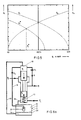
- the valve opening of a control valve 3 connected downstream of the pressure reducing valve 2 is plotted on the horizontal axis. Plotted on the vertical axis (on the left-hand side) is the oil quantity Q flowing through pressure reducing valve 2, and on the other vertical axis (on the right-hand side) the amount of the reduced pressure P r .
- P r should remain 27.5 bar, and the rate of flow Q should increase in direct proportion to an increased valve opening.
- Figure 3 shows, however, that the reduced pressure P r decreases with an increasing supply pressure P p . In addition, this decrease becomes greater with an increasing valve opening. In the most unfavourable case - maximum valve opening and maximum supply pressure P p - the reduced pressure is decreased from 27.5 to 23.75 bar.
- the throughflow through control valve 3 Figure 1 varies with the square root of the pressure drop ⁇ p, the rate of flow Q flowing through control valve 3 and hence also through the pressure reducing valve 2 will decrease by 30%.
- a sudden decrease in supply pressure P p for example, as a result of the highest load pressure in a multi-consumer hydraulic system dropping out, will greatly increase, both the reduced pressure P r and the rate of flow Q through the control valve of a consumer with a low load pressure P L , and this may lead to dangerous situations.
- a possible solution for this porblem could be the provision of a pre-control valve on the pressure reducing valve 2, to operate the control piston 6 of the pressure reducing valve 2.
- the comparison of P r with P L +P v then takes place on the pre-control valve, and no longer on control piston 6, where the result is affected by the flow forces. It is an extremely difficult, and in addition expensive solution to render the pre-control valve insensitive to the flow forces acting on control piston 6.
- such a pre-control valve only serves to generate an oil stream by means of which the control piston 6 of the reducing valve 2 can be displaced to compensate for deviations in the pressure P r . In the following, it will be considered how such correction streams could be generated by means of fixed restrictions.
- a fixed restriction R i is provided in the feedback conduit 11 in the pressure reducing valve shown in Figure 2.
- the control chamber 10 is connected to the spring chamber 13 through a conduit 16 which incorporates a fixed restriction R o .
- P c P L +P v ⁇ P a
- P c Under the influence of the flow forces, P c can now drop to about 22.5 bar with a slight effect on P r . Accordingly, the valve should be so dimensioned that P s is no more than 5 bar. In the numerical example given hereinbefore, this is satisfied with a control piston diameter of 16 mm with a supply pressure of 350 bar, a load pressure of 20 bar and a maximum throughput of 75 l/min. P s is then about 3.75 bar.
- a restriction R o with the above-defined characteristics is shown in Figure 6A and comprises a vane-controlled nozzle system 17.
- System 17 is housed in a reservoir 20 consisting of two chambers 18, 19 separated from each other by a membrane 21.
- the bottom or auxiliary control chamber 19 is connected through a conduit 23 to the control chamber 10, so that the control pressure P c prevails in chamber 19.
- the top or load pressure chamber 18 is through conduit 16 also connected to control chamber 10, and through conduit 24 to the spring chamber 13.
- Connected to the end of conduit 16 within chamber 18 is a nozzle 25.
- the vane-controlled nozzle system 17 can alternatively be provided adjacent to control chamber 10, where the connection 23 between control chamber 10 and auxiliary control chamber 19 is constituted by a hole with a small diameter in the centre of membrane 21 in opposition to nozzle 25 (see Figure 6B).
- Figure 9 illustrates the effect of the flow forces on P r and Q similarly to Figure 3, with the only difference that, on the right-hand vertical axis of Figure 9 P r varies from 26.5 to 27.5 bar.
Abstract
The invention relates to a pressure reducing valve essentially consisting of
- a cylinder
- a control piston movable in said cylinder, one end of said piston being situated in a control chamber and the other in a spring chamber housing a compression spring biasing the control piston in the opening direction;
- an oil supply chamber in the wall of said cylinder, said oil supply chamber having a connection for a supply pressure conduit and together with a control edge provided on the control piston constituting a variable restriction;
- an oil discharge conduit dispcsed downstream of said restriction for the discharge of oil under a reduced pressure; - a load pressure pilot conduit connected to said spring chamber; and
- a feedback conduit connecting said control chamber to said oil discharge conduit. To compensate for fluid flow forces, the valve is characterized, according to this invention, in that said feedback conduit (11) is provided with a fixed restriction (Ri), and the control chamber (10) is connected through a conduit (16) to the spring chamber (13), in which conduit a pressure-dependent restriction (21, 25) is provided, said control piston (6) occupying a stable position if the rate of flow (Qi) through the fixed restriction (Ri) equals the rate of flow (Qo) through the pressure-dependent restriction (21, 25).
Description
- This invention relates to a pressure reducing valve essentially consisting of a cylinder, a control piston movable in said cylinder, one end of said piston being situated in a control chamber and the other in a spring chamber housing a compression spring biasing the control piston in the opening direction; an oil supply chamber in the wall of said cylinder, said oil supply chamber having a connection for a supply pressure line, and together with a control edge provided on the control piston constituting a variable restriction; an oil discharge line disposed downstream of said restriction for the discharge of oil under a reduced pressure; a load pressure pilot line connected to said spring chamber; and a feedback line connecting said control chamber to said oil discharge line.
- Such pressure reducing valves are often used in hydraulic control systems for adjusting, and maintaining the supply pressure from a pump or source of pressure, subject to large variations, at the correct reduced pressure. It has been found that pressure reducing valves known from practice are not capable of effecting a reduced pressure of constant level independently of variations in the supply pressure. Major deviations are caused by flow forces occurring within the pressure reducing valve, which with increasing supply pressure push the movable control piston of the pressure reducing valve further to its closed position than is necessary to effect a reduced pressure of the desired level.
- It is an object of the present invention to overcome this drawback and to provide a pressure reducing valve with which the desired reduced pressure can be kept virtually constant irrespective of substantial variations in supply pressure. The invention is based upon the insight that such oil streams must be supplied to the control piston of the pressure reducing valve that the control piston occupies a stable position, that is to say, that the oil stream to the control chamber is equal to an oil stream from the control chamber when the reduced pressure has reached the desired level, independently of the spurious forces exerted on the control piston. These oil streams to and from the control chamber can be so controlled, independently of the flow effects occurring in the pressure reducing valve that the stable position occupied by the control piston is adapted to the flow effects occurring within the pressure reducing valve. For this purpose the pressure reducing valve according to the invention is characterized in that said feedback line is provided with a fixed restriction, and the control chamber is connected through a conduit to the spring chamber, in which conduit a pressure-dependent restriction is provided, said control piston occupying a stable position if the rate of flow through the fixed restriction equals the rate of flow through the pressure-dependent restriction.
- Preferably, the pressure-dependent restriction is a vane-controlled nozzle system, the vane of which is constituted by a membrane forming a partition between, on the one hand, an auxiliary control chamber connected to the control chamber, and on the other hand, a load pressure chamber connected to the spring chamber, in which load pressure chamber the nozzle is arranged.
- One embodiment of the pressure reducing valve according to the invention will be described in more detail with reference to the accompanying drawings. In said drawings,
- Figure 1 shows an application of a pressure reducing valve in an hydraulic control system for one consumer;
- Figure 2 is a diagrammatic representation of a known, directly-controlled pressure reducing valve;
- Figure 3 is a graph indicating the variation in reduced pressure when the supply pressure changes in a valve illustrated in Figure 2;
- Figure 4 is a pressure reducing valve pre-controlled with fixed restrictions;
- Figure 5 shows the variation of the control streams as a function of the pressure in the control chamber in a valve illustrated in Figure 4;
- Figure 6A is a diagrammatic representation of a pressure reducing valve according to the present invention;
- Figure 6B shows a variant of the pressure reducing valve illustrated in Figure 6A;
- Figure 7 shows the variation of the control streams in a valve according to Figure 6;
- Figure 8 shows the variation of the controlled pressure Pr as a function of the pressure in the control chamber; and
- Figure 9 shows the rate of flow Q of the control system illustrated in Figure 1 when a pressure reducing valve shown in Figure 6 is used with variable supply pressure.
- Figure 1 shows an hydraulic control system for one consumer, for example, a double-acting lifting cylinder (not shown). The control system comprises a pump or pressure source 1 which provides a supply pressure Pp, which for example can vary between 0 and 350 bar. The supply pressure Pp is reduced in a
pressure reducing valve 2 to Pr, and this reduced pressure is supplied to acontrol valve 3, to which two ports A, B are connected, which through pressure conduits are connected to the double-acting lifting cylinder. In the position shown, port A is open, and port B is connected to the return conduit to an oil reservoir. The counter-pressure to be overcome in port A - the load pressure PL - is returned to thepressure reducing valve 2 and to pump 1. To effect a controlled operation of the lifting cylinder, it is necessary that the pressure differential Δp = Pr―PL acrosscontrol valve 3 is constant, so that at a given position of valve 3 a constant quantity of oil flows through the control valve. This pressure differential Δp must be independent of variations in the supply pressure Pp and the load pressure PL. Thepressure reducing valve 2 has the duty to keep this Δp constant. - Figure 2 is a diagrammatic representation of a conventional directly-controlled pressure reducing valve. Valve 2 consists of a cylinder 4 with an oil supply chamber 5 provided in the wall thereof, to which the supply pressure Pp is connected. Housed in cylinder 4 is a freely-
movable control piston 6, consisting of twopiston blocks 7, 8 and a connectingportion 9 of smaller diameter. Disposed abovepiston block 7 is acontrol chamber 10, which through afeedback conduit 11 is connected to theoil discharge conduit 12 at the reduced pressure Pr. Disposed below piston block 8 is aspring chamber 13 with acompression spring 14. Connected further tospring chamber 13 is apilot conduit 15 for supplying the load pressure PL tospring chamber 13. The bottom or control edge ofpiston block 7 cooperates with the rim of the oil supply chamber 5 to form a variable restriction R, through which an oil stream Q flows from the supply pressure connection Pp to the oil discharge conduit 12 at pressure Pr. -
Control piston 6 is subjected to the following forces or pressures:
In the opening direction: - the load pressure PL
- the spring force Fv
This spring force Fv provides a pressure Pv=Fv/A, where A is the surface area of the piston.
In the closing direction:- the pressure Pr incontrol chamber 10
-the flow forces Fs, which provide a closing pressure Ps=Fs/A.
from the equilibrium of forces oncontrol piston 6, it follows therefore that:
Pr=PL+Pv―Ps. - When Ps=Fs/A is absent or neglected (by selecting A large), the pressure drop Δp across control valve 3 (Figure 1) is exclusively determined by the spring force Fv. When spring force Fv is constant, i.e., the spring is weak, the pressure drop Δp across
control valve 3 continues to equal Pv=Fv/A. At a load pressure PL=20 bar and a desired Δp=7.5 bar, Pr should be and remain =27.5 bar. - Figure 3 shows the effect which flow forces have on a pressure reducing valve of the type illustrated in Figure 2 with a maximum throughput of 75 l/min and a control piston diameter of 16 mm, when the supply pressure Pp is varied by increments of 50 bar from 50 to 350 bar at a load pressure PL=20 bar. The valve opening of a
control valve 3 connected downstream of thepressure reducing valve 2 is plotted on the horizontal axis. Plotted on the vertical axis (on the left-hand side) is the oil quantity Q flowing throughpressure reducing valve 2, and on the other vertical axis (on the right-hand side) the amount of the reduced pressure Pr. In the ideal case, Pr should remain 27.5 bar, and the rate of flow Q should increase in direct proportion to an increased valve opening. - Figure 3 shows, however, that the reduced pressure Pr decreases with an increasing supply pressure Pp. In addition, this decrease becomes greater with an increasing valve opening. In the most unfavourable case - maximum valve opening and maximum supply pressure Pp - the reduced pressure is decreased from 27.5 to 23.75 bar. As the throughflow through control valve 3 (Figure 1) varies with the square root of the pressure drop Δp, the rate of flow Q flowing through
control valve 3 and hence also through thepressure reducing valve 2 will decrease by 30%. A sudden decrease in supply pressure Pp, for example, as a result of the highest load pressure in a multi-consumer hydraulic system dropping out, will greatly increase, both the reduced pressure Pr and the rate of flow Q through the control valve of a consumer with a low load pressure PL, and this may lead to dangerous situations. - A possible solution for this porblem could be the provision of a pre-control valve on the
pressure reducing valve 2, to operate thecontrol piston 6 of thepressure reducing valve 2. The comparison of Pr with PL+Pv then takes place on the pre-control valve, and no longer oncontrol piston 6, where the result is affected by the flow forces. It is an extremely difficult, and in addition expensive solution to render the pre-control valve insensitive to the flow forces acting oncontrol piston 6. In principle, such a pre-control valve only serves to generate an oil stream by means of which thecontrol piston 6 of the reducingvalve 2 can be displaced to compensate for deviations in the pressure Pr. In the following, it will be considered how such correction streams could be generated by means of fixed restrictions. - In Figure 4, a fixed restriction Ri is provided in the
feedback conduit 11 in the pressure reducing valve shown in Figure 2. Thecontrol chamber 10 is connected to thespring chamber 13 through aconduit 16 which incorporates a fixed restriction Ro. The restrictions Ri and Ro are equal and have been so selected that with a maximum occurring pressure drop Δp=Fv/A across such restrictions, acceptable values are obtained for the rates of throughflow Qi and Qo with a view to the reaction velocity of the pressure reducing valve and the losses thereby caused. - Within
control chamber 10, a control pressure Pc=PL+Pv―Ps prevails. The rate of throughflow Qi is determined by the pressure drop Pr―Po across the restriction Ri, and Qo by the pressure drop Pc―PL=Pv―Ps across Ro. - The
control piston 6 is stationary, if Qi=Qo, so that, as Ri=Ro, in that case the pressure drop across Ri must be equal to the pressure drop across Ro, i.e. Pr―Pc=Pv―Ps. With Pc=PL+Pv―Pa, it follows that the reduced pressure Pr=PL+2Pv―2Ps. The variation of Qi and Qo in dependence upon Pc and with a constant Pr of 27.5 bar (this is the desired value of Pr when PL=20 bar) are shown in Figure 5. It will be seen that in this case a stable position of equilibrium of thecontrol piston 6 occurs when Pc=23.75 bar. Accordingly, when the flow forces are neglected, the spring pressure should be so dimensioned in this case that Pv=3.75 bar. When, under the influence of flow forces, Pc is decreased to Pc*, Qo will become lower and Qi initially higher. As a consequence, the oil volume ofcontrol chamber 10 will be increased, so that the control piston is going to close, and the resistance of Pp to Pr rises and Pr is going to decrease. As a consequence, Qi also decreases, and another position of equilibrium is established, in which Qi* equals the value of Qo associated with Pc*. But Pr is now accordingly lower than desirable. - As compared with the valve illustrated in Figure 2, therefore, Pv has been reduced from 7.5 to 3.75 bar, and the effect of the flow forces Fs is twice as large.
- A solution for the undesirable dependence of Pr on Pc which varies under the influence of various loads, can be found by making the restriction Ro so pressure-sensitive that the throughflow characteristics for Qi and Qo in Figure 5 coincide. Then with Pr=27.5 bar Qi will always be =Qo, i.e. in particular independently of Pc, and the
control piston 6 will remain stationary at that value of Pr. This is best achieved in practice in a range in which Pc varies from 22.5 to 27.5-bar (with PL=20 bar). To this effect, the spring pressure is increased to Pv=7.5 bar so that, without flow forces, Pc=27.5 bar and hence Qi is zero, because the pressure drop across Ri is now zero. Under the influence of the flow forces, Pc can now drop to about 22.5 bar with a slight effect on Pr. Accordingly, the valve should be so dimensioned that Ps is no more than 5 bar. In the numerical example given hereinbefore, this is satisfied with a control piston diameter of 16 mm with a supply pressure of 350 bar, a load pressure of 20 bar and a maximum throughput of 75 l/min. Ps is then about 3.75 bar. - A restriction Ro with the above-defined characteristics is shown in Figure 6A and comprises a vane-controlled
nozzle system 17.System 17 is housed in areservoir 20 consisting of twochambers membrane 21. The bottom orauxiliary control chamber 19 is connected through aconduit 23 to thecontrol chamber 10, so that the control pressure Pc prevails inchamber 19. The top orload pressure chamber 18 is throughconduit 16 also connected to controlchamber 10, and throughconduit 24 to thespring chamber 13. Connected to the end ofconduit 16 withinchamber 18 is anozzle 25. The vane-controllednozzle system 17 can alternatively be provided adjacent to controlchamber 10, where theconnection 23 betweencontrol chamber 10 andauxiliary control chamber 19 is constituted by a hole with a small diameter in the centre ofmembrane 21 in opposition to nozzle 25 (see Figure 6B). -
Membrane 21 is arranged so thatnozzle 25 is closed if the pressure differential across the membrane 21 Pc―PL equals 7.5 bar, i.e., equals the spring pressure Fv/A. If Pc-PL equals or exceeds 7.5 bar, the reducing valve illustrated in Figure 6 will operate in the same way as that shown in Figure 2, with Pr=Pc and Pc=PL+Pv and Qi=Qo=0. If Pc―PL is decreased below the desired pressure drop of 7.5 bar, then owing to the decrease of Pc membrane 21 will be released fromnozzle 25 and an oil stream Qo will begin to flow fromcontrol chamber 10, throughnozzle 25 tochamber 18 abovemembrane 21 and further tospring chamber 13. In addition, an oil current Qi will begin to flow through Ri, because Pc has decreased below the value of Pr=27.5 bar. As the throughflow characteristics for Qi and Qo have now been made equal, however, Qi will still be =Qo, also when Pc is decreased. Accordingly, the control piston remains stationary, and Pr retains the desired value of 27.5 bar. - The variation of Qi and Qo in the valve illustrated in Figure 6 is shown in Figure 7 in dependence upon Pc, with PL=20 bar and Pr=27.5 bar. In the range between 22.5 and 27.5 bar, the deviation between Qi and Qo is very slight, so that the correction of Pr to provide for Qi=Qo will also be slight. This is shown even better in Figure 8, in which Pr is shown as a function of Pc. It will be seen that in the range between 22.5 and 27.5 bar Pr is virtually independent of Pc. An increase in the flow forces to about Ps=5 bar can be absorbed virtually without any variation of Pr.
- Figure 9 illustrates the effect of the flow forces on Pr and Q similarly to Figure 3, with the only difference that, on the right-hand vertical axis of Figure 9 Pr varies from 26.5 to 27.5 bar. An increase or decrease of the supply pressure Pp Only has a slight effect on the value of Pr. The oil stream Q, too, remains virtually directly proportional to the amount of the valve opening.
Claims (7)
1. A pressure reducing valve essentially consisting of
- a cylinder
- a control piston movable in said cylinder, one end of said piston being situated in a cortrol chamber and the other in a spring chamber housing a compression spring biasing the control piston in the opening direction;
- an oil supply chamber in the wall of said cylinder, said oil supply chamber having a connection for a supply pressure conduit and together with a control edge provided on the control piston constituting a variable restriction;
- an oil discharge conduit disposed downstream of said restriction for the discharge of oil under a reduced pressure;
- a load pressure pilot conduit connected to said spring chamber; and
- a feedback conduit connecting said control chamber to said oil discharge conduit,
characterized in that said feedback conduit (11) is provided with a fixed restriction (Ri), and the control chamber (10) is connected through a conduit (16) to the spring chamber (13), in which conduit a pressure-dependent restriction (21, 25) is provided, said control piston (6) occupying a stable position if the rate of flow (Qi) through the fixed restriction (Ri) equals the rate of flow (Qo) through the pressure-dependent restriction (21, 25).
2. A pressure reducing valve as claimed in claim 1, characterized in that the rate of flow (Qo) through the pressure-dependent restriction (Ro; 21, 25) as a result of the pressure differential (Pc―PL) is equal to, or virtually equal to, the rate of flow (Qi) through a fixed restriction (Ri) as a result of a pressure differential (Pr―Pc), which restriction (Ri) is provided in series with the pressure-dependent restriction (Ro; 21, 25), upon the occurrence of variations of the control pressure (Pc) and a fixed value of the pressure differential (Pr―PL).
3. A pressure reducing valve as claimed in claims 1-2, characterized in that the pressure-dependent restriction (21, 25) is closed if the pressure (Pc) within the control chamber (10) of the pressure reducing valve equals or exceeds the sum of the spring pressure (Fv/A) provided by the spring (14) within the spring chamber (13) and the load pressure (PL).
4. A pressure reducing valve as claimed in claims 1-3, characterized in that the pressure dependent restriction (21, 25) is a vane-controlled nozzle system (17), the vane of which is constituted by a membrane (21) forming a partition between, on the one hand, an auxiliary control chamber (19) connected by means of a conduit (23) to the control chamber (10), and on the other hand, a load pressure chamber (18) connected to the spring chamber (13), in which load pressure chamber (18) said nozzle (25) is provided.
5. A pressure reducing valve as claimed in claim 4, characterized in that the connecting conduit (23) between said auxiliary control chamber (19) and said control chamber (10) is constituted by a hole of small diameter, provided in the centre of said membrane (21) in opposition to said nozzle (25).
6. A pressure reducing valve as claimed in either of claims 4-5, characterized in that said membrane (21) is dimensioned so that the rate of flow (Qo) through said nozzle (25) initially increases upon a decrease of the pressure differential (Pc―PL) across the membrane (21).
7. A pressure reducing valve as claimed in claim 6, characterized in that the maximum rate of flow (Qo) through said nozzle (25) is reached when the pressure differential between the reduced pressure (Pr) and the control pressure (Pc) in said control chamber (10) is equal to the pressure (Fs/A) exerted in the closing direction on the control piston (6) by the flow forces with a maximum supply pressure (Pp) and a maximum throughput volume (Q).
Applications Claiming Priority (2)
| Application Number | Priority Date | Filing Date | Title |
|---|---|---|---|
| NL8902364 | 1989-09-21 | ||
| NL8902364A NL8902364A (en) | 1989-09-21 | 1989-09-21 | PRESSURE REDUCING VALVE WITH FLOW FORCE COMPENSATION. |
Publications (1)
| Publication Number | Publication Date |
|---|---|
| EP0418982A1 true EP0418982A1 (en) | 1991-03-27 |
Family
ID=19855341
Family Applications (1)
| Application Number | Title | Priority Date | Filing Date |
|---|---|---|---|
| EP90202495A Ceased EP0418982A1 (en) | 1989-09-21 | 1990-09-20 | A pressure reducing valve with flow forces compensation |
Country Status (4)
| Country | Link |
|---|---|
| US (1) | US5029609A (en) |
| EP (1) | EP0418982A1 (en) |
| JP (1) | JPH03130811A (en) |
| NL (1) | NL8902364A (en) |
Families Citing this family (3)
| Publication number | Priority date | Publication date | Assignee | Title |
|---|---|---|---|---|
| JP3182717B2 (en) * | 1996-06-06 | 2001-07-03 | 株式会社山武 | Control valve abnormality detection method and detection device |
| DE10158873A1 (en) * | 2001-11-30 | 2003-06-12 | Daimler Chrysler Ag | Hydraulic exhaust valve actuation |
| SE2250011A1 (en) | 2022-01-10 | 2023-07-11 | Parker Hannifin Emea Sarl | A counter pressure valve arrangement |
Citations (2)
| Publication number | Priority date | Publication date | Assignee | Title |
|---|---|---|---|---|
| DE516247C (en) * | 1927-12-03 | 1932-02-20 | Julius Pintsch Akt Ges | Gas pressure regulator for installation in inhabited rooms with control pressure regulator |
| GB2211916A (en) * | 1987-11-05 | 1989-07-12 | Rolls Royce Plc | Pressure response flow control valve assembly |
Family Cites Families (5)
| Publication number | Priority date | Publication date | Assignee | Title |
|---|---|---|---|---|
| US2264262A (en) * | 1940-04-09 | 1941-11-25 | Charles Tagliabue Mfg Co | Valve positioner |
| US3495619A (en) * | 1965-10-22 | 1970-02-17 | Shoketsu Kinzoku Kogyo Kk | Reducing valve |
| US3389718A (en) * | 1966-09-16 | 1968-06-25 | Fisher Governor Co | High and low pressure wellhead shut-in valve |
| US3583422A (en) * | 1967-10-19 | 1971-06-08 | Zahnradfabrik Friedrichshafen | Valve construction for controlled pressure buildup in fluid-operated brake or clutch |
| US4362089A (en) * | 1980-06-16 | 1982-12-07 | Caterpillar Tractor Co. | Valve system |
-
1989
- 1989-09-21 NL NL8902364A patent/NL8902364A/en not_active Application Discontinuation
-
1990
- 1990-09-20 EP EP90202495A patent/EP0418982A1/en not_active Ceased
- 1990-09-20 US US07/585,491 patent/US5029609A/en not_active Expired - Fee Related
- 1990-09-21 JP JP2250461A patent/JPH03130811A/en active Pending
Patent Citations (2)
| Publication number | Priority date | Publication date | Assignee | Title |
|---|---|---|---|---|
| DE516247C (en) * | 1927-12-03 | 1932-02-20 | Julius Pintsch Akt Ges | Gas pressure regulator for installation in inhabited rooms with control pressure regulator |
| GB2211916A (en) * | 1987-11-05 | 1989-07-12 | Rolls Royce Plc | Pressure response flow control valve assembly |
Also Published As
| Publication number | Publication date |
|---|---|
| NL8902364A (en) | 1991-04-16 |
| JPH03130811A (en) | 1991-06-04 |
| US5029609A (en) | 1991-07-09 |
Similar Documents
| Publication | Publication Date | Title |
|---|---|---|
| US5342023A (en) | Hydraulic control device for active suspension system | |
| JP4739529B2 (en) | Control unit for at least two hydraulic consumers and differential pressure valve for the control unit | |
| US3763746A (en) | Hydraulic actuator controls | |
| US4821773A (en) | Directional control valve | |
| WO2002012732A3 (en) | Hydraulic control valve system with pressure compensated flow control | |
| US4756330A (en) | Flow divider valve | |
| US6073652A (en) | Pilot solenoid control valve with integral pressure sensing transducer | |
| CA2255991A1 (en) | Hydraulic control valve system with load sensing priority | |
| US4168721A (en) | Pressure control valve | |
| JP2579202Y2 (en) | Operating valve with pressure compensation valve | |
| GB2113310A (en) | Device for controlling a hydromotor | |
| US4809746A (en) | Proportional throttle valve | |
| US5366236A (en) | Hydraulic control device for active suspension system | |
| US5433237A (en) | Dedrooped bypass valve | |
| US20100307621A1 (en) | Hydraulic valve device | |
| US3878765A (en) | Hydraulic actuator controls | |
| EP0008523B1 (en) | Improvements relating to hydraulic control systems | |
| US5222426A (en) | Proportional distributor and control system for a plurality of hydraulic receivers incorporating a distributor of this kind for each receiver | |
| US20200378409A1 (en) | Valve device | |
| US5029609A (en) | Pressure reducing valve with flow forces compensation | |
| US4436114A (en) | Hydraulic valve mechanism | |
| US5513958A (en) | Accumulator charging valve | |
| JP2706483B2 (en) | Pressure control valve | |
| JPH0448969B2 (en) | ||
| US5326230A (en) | Closed loop control circuit for variable hydraulic pump |
Legal Events
| Date | Code | Title | Description |
|---|---|---|---|
| PUAI | Public reference made under article 153(3) epc to a published international application that has entered the european phase |
Free format text: ORIGINAL CODE: 0009012 |
|
| AK | Designated contracting states |
Kind code of ref document: A1 Designated state(s): AT BE CH DE DK ES FR GB GR IT LI LU NL SE |
|
| 17P | Request for examination filed |
Effective date: 19911107 |
|
| 17Q | First examination report despatched |
Effective date: 19931222 |
|
| STAA | Information on the status of an ep patent application or granted ep patent |
Free format text: STATUS: THE APPLICATION HAS BEEN REFUSED |
|
| 18R | Application refused |
Effective date: 19940616 |