EP0418958A2 - Method and device for converting an analog input signal into control codes and for synthesizing a corresponding output signal under the control of those control codes - Google Patents
Method and device for converting an analog input signal into control codes and for synthesizing a corresponding output signal under the control of those control codes Download PDFInfo
- Publication number
- EP0418958A2 EP0418958A2 EP90202432A EP90202432A EP0418958A2 EP 0418958 A2 EP0418958 A2 EP 0418958A2 EP 90202432 A EP90202432 A EP 90202432A EP 90202432 A EP90202432 A EP 90202432A EP 0418958 A2 EP0418958 A2 EP 0418958A2
- Authority
- EP
- European Patent Office
- Prior art keywords
- pulse
- signal
- pulse signal
- signals
- pulse signals
- Prior art date
- Legal status (The legal status is an assumption and is not a legal conclusion. Google has not performed a legal analysis and makes no representation as to the accuracy of the status listed.)
- Granted
Links
Images


Classifications
-
- G—PHYSICS
- G10—MUSICAL INSTRUMENTS; ACOUSTICS
- G10L—SPEECH ANALYSIS OR SYNTHESIS; SPEECH RECOGNITION; SPEECH OR VOICE PROCESSING; SPEECH OR AUDIO CODING OR DECODING
- G10L19/00—Speech or audio signals analysis-synthesis techniques for redundancy reduction, e.g. in vocoders; Coding or decoding of speech or audio signals, using source filter models or psychoacoustic analysis
- G10L19/04—Speech or audio signals analysis-synthesis techniques for redundancy reduction, e.g. in vocoders; Coding or decoding of speech or audio signals, using source filter models or psychoacoustic analysis using predictive techniques
- G10L19/08—Determination or coding of the excitation function; Determination or coding of the long-term prediction parameters
- G10L19/10—Determination or coding of the excitation function; Determination or coding of the long-term prediction parameters the excitation function being a multipulse excitation
- G10L19/113—Regular pulse excitation
Definitions
- the invention relates to a method for coding an analog signal occurring with a certain time interval, said analog signal being converted into control codes which can be used for assembling a synthetic signal corresponding to said analog signal.
- the invention also relates to an apparatus for carrying out such a method.
- the invention relates to a method and apparatus for coding speech signals as digital signals having a low bit frequency.
- an analog (speech) signal (after linear predictive coding (LPC)) is successively converted into a pulse signal composed of pulses at equal (time) spacing from one another, the amplitude of said pulses corresponding to the respective instantaneous amplitudes of the analog signal.
- that pulse signal is then selected which approximates best to the first pulse signal.
- the first pulse signal is then compared with a set of various third pulse signals, all composed of a number of pulses at mutually different spacings and having mutually different amplitudes, but all of which belong to one and the same class and of which the position of the most significant pulse corresponds to the position of the selected second pulse signal. From this set, that third pulse signal is then selected which corresponds most to the first pulse signal.
- the characteristics of said third pulse signal are used as a control code for assembling a synthetic signal corresponding to said analog signal.
- the characteristics of said third pulse signal are used as a control code for assembling a synthetic signal corresponding to said analog signal.
- only a limited set of third pulse signals has to be searched for correspondence, instead of all the third pulse signals of all the sets; in other words, only a part (characterized by the relevant class) of a large set has to be searched instead of said set in its entirety.
- a drawback of the known method is that it does not fit in with the present GSM (Grouppe Spéciale Mobile) practice.
- the object of the invention is to provide an alternative to the known method or apparatus which is in fact compatible with the GSM system.
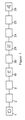
- FIGS 1, 2 and 3 show a functional block diagram for the application of the system described, having a transmitter 19 and a receiver 29 for transmitting a digital speech signal over a channel 30 whose transmission capacity is much lower than the value of 64 kbit/s of a standard PCM channel for telephony.
- Said digital speech signal represents an analog speech signal originating from a source 1 having a microphone or other electroacoustical transducer and limited to a speech band ranging from 0 to 4 kHz with the aid of a low pass filter 2.
- Said analog speech signal is sampled with a sampling frequency of 8 kHz and converted into a digital code suitable for use in the transmitter 19 with the aid of an analog/digital converter 3 which also subdivides said digital speech signals into segments of 20 ms (160 samples) which are replaced every 20 ms.
- said digital speech signal is processed to form a code signal having a bit frequency in the region around 6 kbit/s which is transmitted via channel 30 to receiver 29 and is processed therein to form a digital synthetic speech signal which, by means of a digital-analog converter 24, is converted into an analog speech signal which after being limited in a low pass filter 25 is fed to a reproduction circuit 26 having a loudspeaker or another electroacoustical transducer.
- Transmitter 19 contains the Restricted Search Code Excited Linear Predictive coder (RSCELP coder) 17 which makes use of linear predictive coding (LPC) as a method of spectral analysis.
- the segments of the digital speech signal s(n) are fed to the first conversion device 7 composed of an LPC analyser 5, an analysing filter 4 and a weighting filter 6.
- the speech signal s(n) is fed to an LPC analyser 5 in which the LPC parameters of a 20 ms speech segment are calculated every 20 ms in a known manner, for example on the basis of the autocorrelation method or the covariance method of linear prediction (cf. L.R. Rabiner and R.W. Schafer, "Digital Processing of Speech Signals", Prentice-Hall, Englewood Cliffs, 1978, chapter 8, pages 396-421).
- the LPC parameter a(i) is determined in a manner such that, at the output of filter 4, a prediction residual signal rp(n) appears having as flat as possible a segment period (20 ms) of the spectral envelope. Filter 4 is therefore known as an inverse filter.
- the LPC parameters are transmitted via channel 30 to the receiver 29.
- the prediction residual signal rp(n) is filtered by the weighting filter 6.
- the object of said weighting filter is to perceptually weight the prediction residual signal rp(n). Backgrounds and examples are given in EP-195,487. This results in the weighted prediction residual signal rpw(n) denoted above as first pulse signal.
- the weighted prediction residual signal rpw(n) is fed to the second conversion device 8.
- the first selector 9 selects 1 of the 4 subpulse signals dp(j,m) on the basis of the segmental energy.
- the selected subpulse signal dps(m) is set equal to dp(j,m) and the selection value J (denoted above as first control code) is set equal to j for that value of j for which it holds true that the segmental energy Eseg(j) is greatest.
- the selection value J is transmitted via channel 30 to the receiver 29.
- the transmitter 19 has a codebook 13. Said codebook 13 is made up of 256 codebook rows.
- Each codebook row is filled with 10 arbitrary numbers, of which the probability distribution of the values of the numbers is distributed in a Gaussian manner.
- the second selector 10 selects sequential codebook row 1 to row 256 inclusive from the codebook 13. Every time a codebook row is selected from the codebook 13, this row of 10 numbers will be delivered to the excitation generator 14.
- pulses having amplitude zero are added to the 10 pulses p(r).
- the excitation generator signal eg(m) is presented together with the selected subpulse signal dps(m) to the scaling device 11 via the amplifier 12.
- the scaling device 11 now adjusts the gain factor V of the amplifier 12 in a manner such that the degree of error fm is a minimum, it holding true for fm that:
- the minimum degree of error is denoted by fmmin.
- the values of the minimum degree of error fmmin are transmitted to the second selector 10.
- the receiver 29 contains a Restricted Search Code Excited Linear Predictive decoder (RSCELP decoder) 27.
- the receiver 29 comprises, inter alia, a codebook 20, excitation generator 21 and amplifier 22 which are exactly identical to codebook 13, excitation generator 12 and amplifier 11 of the transmitter 19.
- the optimum gain factor Vopt and selection value J With the aid of the values, received by the receiver 29, of the selected codebook row Rs, the optimum gain factor Vopt and selection value J, the value, calculated in the transmitter 19, for the amplified excitation generator signal Vopt*eg(m) can be calculated in the receiver 29 with the aid of the codebook 20 and excitation generator 21 and amplifier 22. This signal is denoted by receiver pulse signal po(m).
- the receiver pulse signal po(m) therefore matches the selected subpulse signal dps(m) in the transmitter 19 as well as possible.
- the receiver pulse signal po(m) is presented to the LPC synthesizing filter 23.
- the LPC synthesizing filter 23 is the inverse filter of the LPC analysing filter 4 in the receiver 19.
- the transfer function, noted in the z-transform notation, of the LPC synthesizing filter 23 is therefore equal to: A(z) ⁇ 1.
- the synthesizing filter 23 is adjusted for each segment (20 ms) with the aid of the LPC parameter received.
- the receiver pulse signal po(m) is calculated every 5 ms, with the result that after every fourth receiver pulse signal po(m) which is presented to the synthesizing filter 23, the LPC filter parameters are readjusted.
- the synthesizing filter output signal is converted, by means of a digital/analog converter 24 and a low pass filter 25 into an analog speech signal which can be made audible by means of an electroacoustic transducer.
Abstract
■ in that the analog signal is converted into a first pulse signal composed of pulses at a mutually equal time interval, the pulse amplitude of said pulses corresponding to that of the analog signal at that instant;
■ in that the first pulse signal is converted into a series of p second pulse signals which are each likewise composed of a fixed number of pulses at a mutually equal time spacing which is, however, a multiple of that of the first pulse signal, while the pulse amplitude likewise corresponds to that of the analog signal at that instant,
in which connection, of the successive second pulse signals of said series, the position of the first pulse of the respective second pulse signal, viewed in the time domain, is shifted in time with respect to the start thereof over a spacing equal to a multiple n of the said time spacing of the first pulse signal, n successively increasing from 0 to p;
■ in that that second pulse signal whose correspondence to the first pulse signal is the greatest is selected from the various second pulse signals and that a first control code for assembling the synthetic signal corresponding to the analog signal is generated in accordance with the time spacing between the start and the first pulse of said selected second pulse signal;
■ in that the said first pulse signal is compared with a set of various third pulse signals which are each composed of pulses at a mutually equal time spacing equal to that of the second pulse signals, which pulses have various pulse amplitudes and in which connection, of all said third pulse signals, the position of the first pulse of the respective third pulse signal, viewed in the time domain, is shifted in time with respect to the start thereof over a spacing which is equal to that of the selected second pulse signal;
■ in that that third pulse signal whose correspondence to the first pulse signal is the greatest is selected from the said set and that a second control code for assembling the synthetic signal corresponding to the analog signal is generated in accordance with the order number of said selected third pulse signal. Instead of comparing the first pulse signal with the various third pulse signals from the said set (after which said third pulse signal whose correspondence to said first pulse signal is greatest is selected from said set) it is also possible (and preferable) for the (previously) selected second pulse signal to be compared with the various third pulse signals (after which that third pulse signal whose correspondence to said selected second pulse signal is the greatest is selected.
Description
- The invention relates to a method for coding an analog signal occurring with a certain time interval, said analog signal being converted into control codes which can be used for assembling a synthetic signal corresponding to said analog signal. The invention also relates to an apparatus for carrying out such a method. In particular, the invention relates to a method and apparatus for coding speech signals as digital signals having a low bit frequency.
- Such a method or apparatus is disclosed by EP-307,122. According to the known method, an analog (speech) signal (after linear predictive coding (LPC)) is successively converted into a pulse signal composed of pulses at equal (time) spacing from one another, the amplitude of said pulses corresponding to the respective instantaneous amplitudes of the analog signal. A series of p second pulse signals is then generated, all of which are composed of only one pulse, of which, however, the position (in the time domain) of said pulse successively increases with respect to the start of the second pulse signal according to the series based on n times the time spacing of the first pulse signal, where n = 0 ... p. Of said second pulse signals, that pulse signal is then selected which approximates best to the first pulse signal. The first pulse signal is then compared with a set of various third pulse signals, all composed of a number of pulses at mutually different spacings and having mutually different amplitudes, but all of which belong to one and the same class and of which the position of the most significant pulse corresponds to the position of the selected second pulse signal. From this set, that third pulse signal is then selected which corresponds most to the first pulse signal. According to the known method, the set of third pulse signals forms part of a group of such sets, each set having its own class as regards the position of the most significant pulse. By selecting the best second (one-) pulse signal, that set (=class) is therefore indicated which has to be searched for correspondence to the first pulse signal. After selecting the most corresponding third pulse signal, the characteristics of said third pulse signal are used as a control code for assembling a synthetic signal corresponding to said analog signal. In the proposed manner, only a limited set of third pulse signals has to be searched for correspondence, instead of all the third pulse signals of all the sets; in other words, only a part (characterized by the relevant class) of a large set has to be searched instead of said set in its entirety.
- A drawback of the known method is that it does not fit in with the present GSM (Grouppe Spéciale Mobile) practice.
- The object of the invention is to provide an alternative to the known method or apparatus which is in fact compatible with the GSM system.
- 1. The invention therefore provides a method for coding an analog signal occurring within a certain time interval, said analog signal being converted into control codes which can be used for assembling a synthetic signal corresponding to said analog signal, which method is characterized
■ in that the analog signal is converted into a first pulse signal composed of pulses at a mutually equal time interval, the pulse amplitude of said pulses corresponding to that of the analog signal at that instant;
■ in that the first pulse signal is converted into a series of p second pulse signals which are each likewise composed of a fixed number of pulses at a mutually equal time spacing which is, however, a multiple of that of the first pulse signal, while the pulse amplitude likewise corresponds to that of the analog signal at that instant, in which connection, of the successive second pulse signals of said series, the position of the first pulse of the respective second pulse signal, viewed in the time domain, is shifted in time with respect to the start thereof over a spacing equal to a multiple n of the said time spacing of the first pulse signal, n successively increasing from 0 to p;
■ in that that second pulse signal whose correspondence to the first pulse signal is the greatest is selected from the various second pulse signals and in that a first control code for assembling the synthetic signal corresponding to the analog signal is generated in accordance with the time spacing between the start and the first pulse of said selected second pulse signal;
■ in that the said first pulse signal is compared with a set of various third pulse signals which are each composed of pulses at a mutually equal time spacing equal to that of the second pulse signals, which pulses have various pulse amplitudes and in which connection, of all said third pulse signals, the position of the first pulse of the respective third pulse signal, viewed in the time domain, is shifted in time with respect to the start thereof over a spacing which is equal to that of the selected second pulse signal;
■ in that that third pulse signal whose correspondence to the first pulse signal is the greatest is selected from the said set and in that a second control code for assembling the synthetic signal corresponding to the analog signal is generated in accordance with the order number of said selected third pulse signal. - 2. Instead of the first pulse signal being compared with the various third pulse signals of the said set (after which that third pulse signal whose correspondence to said first pulse signal is the greatest is selected from said set) it is also possible (and preferable), for the (previously) selected second pulse signal to be compared with the various third pulse signals, after which that third pulse signal whose correspondence to the selected second pulse signal is the greatest, is selected.
In relation to the above measures, it is pointed out that converting the first pulse signal into a series of second pulse signals of the specified type is disclosed per se in EP-195,487. According to the method and apparatus described therein, however, no use is made of a set of third pulse signals of the specified type with which the first pulse signal or the previously selected second pulse signal is compared and from which a corresponding third pulse signal is selected, as is in fact the case according to the invention. - 3. A further development of the invention may provide
■ that the said set of third signals forms part of a group of such sets, each of said sets, like the set already mentioned, comprising mutually different pulse signals which are composed of pulses at a mutually equal time spacing which is equal to that of the said second pulse signals and having different pulse amplitudes, for each set the position of the first pulse of all those pulse signals, viewed in time, being identical with respect to the start thereof;
■ that, after the previously mentioned selection of the second pulse signal which corresponds most to the first pulse signal, that set whose position of the first pulse of the pulse signals with respect to the start thereof, viewed in time, is identical to that of the selected second pulse signal is selected from the said group of sets. In other words, the said set of third pulse signals is in fact a part of a greater set, but only that part (the most relevant) is searched for correspondence to the first pulse signal or the previously selected second pulse signal. - 4. Preferably, however, a further development of the invention provides in
■ that the said set of third pulse signals is a virtual set which is generated from a basic set of mutually different fourth pulse signals, each being composed of pulses at a mutually equal time spacing equal to that of the second pulse signals, which pulses have various pulse amplitudes and in which connection, of all said fourth pulse signals, the position of the first pulse, viewed in the time domain, is identical with respect to the position of the start of said fourth pulse signal;
■ that after the previously mentioned selection of the second pulse signal which corresponds most to the first pulse signal, the said virtual set of third pulse signals is generated by shifting each of the said fourth pulse signals in time over a spacing which is equal to the difference between, on the one hand, the spacing between the start and the first pulse of the selected second pulse signal and, on the other hand, the spacing between the start and the first pulse of each of the fourth pulse signals. According to this further development, only a (limited) basic set of (fourth) pulse signals is therefore provided from which (by shifting the pulse signals) the required "search" set is derived. - 5. In particular, the above is provided in
■ that the said set of third pulse signals is a virtual set which is generated from a basic set of mutually different fourth pulse signals, each being composed of pulses at a mutually equal time spacing equal to that of the second pulse signals, which pulses have various pulse amplitudes and in which connection, of all said fourth pulse signals, the position of the first pulse, viewed in the time domain, corresponds to the position of the start of said fourth pulse signal;
■ that, after the previously mentioned selection of the second pulse signal which corresponds most to the first pulse signal, the said virtual set of third pulse signals is generated by shifting each of the said fourth pulse signals in time over a spacing which is equal to the spacing between the start and the first pulse of the selected second pulse signal. The shifting of the fourth pulse signals is in this case therefore equal to the time difference between the start and the first pulse of the previously selected second pulse signal. - 6. The method according to the invention is moreover preferably characterized in that, in the said comparison of the first pulse signal or the selected second pulse signal with the various third pulse signals from the said set and the selection of the required third pulse signal as mentioned, a scaling factor is derived from the respective amplitudes of the pulse signals compared with one another and in that a third control code is generated for assembling the synthetic signal corresponding to the analog signal in accordance with that scaling factor which is associated with the selected third pulse signal.
- 7. An apparatus for carrying out the first mentioned method according to the invention is characterized by
■ a first conversion device for converting the said analog signal into the said first pulse signal;
■ a second conversion device for converting the first pulse signal into the said series of p second pulse signals of which the time spacing between the start of the pulse signal and the first pulse is successively 0 to p times the mutual pulse spacing of the first pulse signal,
■ a first selection device for selecting the second pulse signal which exhibits the most correspondence to the first pulse signal and for delivering a first control code for assembling the synthetic signal corresponding to the analog signal in accordance with the time spacing between the start and the first pulse of the selected second pulse signal,
■ a second selection device for selecting, from the said set of third pulse signals, that third pulse signal which exhibits the most correspondence to the first pulse signal and for delivering a second control code for assembling the synthetic signal corresponding to the analog signal in accordance with the order number of said selected third pulse signal. - 8. If in selecting the required third pulse signal the various third pulse signals are compared not with the first pulse signal but with the previously selected second pulse signal and examined for correspondence, an apparatus for carrying out the method is characterized by
■ a first conversion device for converting the said analog signal into the said first pulse signal;
■ a second conversion device for converting the first pulse signal into the said series of p second pulse signals of which the time spacing between the start of the pulse signal and the first pulse is successively 0 to p times the mutual pulse spacing of the first pulse signal,
■ a first selection device for selecting the second pulse signal which exhibits most correspondence to the first pulse signal and for delivering a first control code for assembling the synthetic signal corresponding to the analog signal in accordance with the time spacing between the start and the first pulse of the selected second pulse signal,
■ a second selection device for selecting, from the said set of third pulse signals, that third pulse signal which exhibits the most correspondence to the selected second pulse signal and for delivering a second control code for assembling the synthetic signal corresponding to the analog signal in accordance with the order number of said selected third pulse signal. The apparatus in the exemplary embodiment to be dealt with below is equipped in this way. - 9. If the "search" set forms part of a group of sets from which (according to an option specified above) a choice has to be made, the apparatus is preferably characterized by a third selection device for selecting, from the said group of pulse signal sets, that set of which the time spacing between the start of the pulse signal and the first pulse of all third pulse signals associated with said set is equal to that of the second pulse signal selected by the first selection device.
- 10. If (according to a second option) the "search" set is a virtual set which is generated from a basic set by shifting the pulse signals from said basic set, the apparatus is characterized by a generator for generating the said virtual set of third pulse signals from a basic set of fourth pulse signals of the said type. The apparatus in the exemplary embodiment to be dealt with below is equipped in this way, ie. it is provided with a generator which, from a basic set of (fourth) pulse signals of which the position of the first pulse coincides with the signal start, generates, by signal displacement, a virtual "search" set composed of (third) pulse signals of which the spacing between the start and the first pulse is equal to that of the selected second pulse signal.
- 11. An apparatus for carrying out the method according to the invention is preferably characterized by a scaling device for deriving, from the amplitude of the first pulse signal or the second pulse signal selected by the first selection device and the respective amplitudes of the various third pulse signals, respective scaling factors and for delivering a third control code for assembling the synthetic signal corresponding to the analog signal in accordance with that scaling factor which corresponds to the selected third pulse signal.
- 12. In particular, an apparatus as specified above is suitable for incorporation in an apparatus for converting analog speech signals into digital signals with a low bit frequency and vice versa, a so-called speech coder/decoder.
- 13. In accordance with the methods for coding an analog signal as disclosed above, the invention also includes a method of synthesizing a signal under the control of the said first, second and third control code, characterized in that the synthesized signal is formed by one from a series of fourth pulse signals, being equal to said series of second pulse signals, that fourth pulse signal being selected under the control of said first control signal, which selected fourth pulse signal is combined with one from a set of fifth pulse signals, being equal to said set of third pulse signals, that fifth pulse signal being selected under the control of said second control signal, which selected and combined fourth and fifth pulse signal are scaled up under the control of said third control signal.
- 14. In accordance with the apparatuses for coding an analog signal as disclosed above, the invention also includes an apparatus for synthesizing a signal under the control of the first, second and third control code, characterized by
■ a third selecting device for selecting from a series of fourth pulse signals, being equal to said series of second pulse signals, one of those fourth pulse signals under the control of said first control signal
■ a fourth selecting device for selecting from a set of fifth pulse signals, being equal to said set of third pulse signals, one of those fifth pulse signals under the control of said second control signal, and for combining those selected fourth and fifth pulse signal
■ a second scaling device for scaling up those selected and combined fourth and fifth pulse signal under the control of said third control signal. -
- EP-307,122 (BRITISH TELECOM)
- EP-195,487 (PHILIPS)
- Figures 1, 2 and 3 show a functional block diagram for the application of the system described, having a
transmitter 19 and areceiver 29 for transmitting a digital speech signal over achannel 30 whose transmission capacity is much lower than the value of 64 kbit/s of a standard PCM channel for telephony. Said digital speech signal represents an analog speech signal originating from a source 1 having a microphone or other electroacoustical transducer and limited to a speech band ranging from 0 to 4 kHz with the aid of alow pass filter 2. Said analog speech signal is sampled with a sampling frequency of 8 kHz and converted into a digital code suitable for use in thetransmitter 19 with the aid of an analog/digital converter 3 which also subdivides said digital speech signals into segments of 20 ms (160 samples) which are replaced every 20 ms. Intransmitter 19, said digital speech signal is processed to form a code signal having a bit frequency in the region around 6 kbit/s which is transmitted viachannel 30 toreceiver 29 and is processed therein to form a digital synthetic speech signal which, by means of a digital-analog converter 24, is converted into an analog speech signal which after being limited in alow pass filter 25 is fed to areproduction circuit 26 having a loudspeaker or another electroacoustical transducer. Transmitter 19 (Figures 1 and 2) contains the Restricted Search Code Excited Linear Predictive coder (RSCELP coder) 17 which makes use of linear predictive coding (LPC) as a method of spectral analysis. SinceRSCELP coder 17 processes a digital speech signal which is representative of the samples s(kT) of an analog speech signal s(t) at instants in time t=kT, where k is an integer and 1/T= B kHz, said digital speech signal is denoted by the standard notation of the type s(k). The analog/digital converter 3 subdivides said signal s(k) into segments of 20 ms. Within the qth segment, the signal is denoted by s(n), where n = 1...160. A notation of this type is likewise used for all the other signals in theRSCELP coder 17. In theRSCELP coder 17, the segments of the digital speech signal s(n) are fed to the first conversion device 7 composed of anLPC analyser 5, an analysingfilter 4 and aweighting filter 6. The speech signal s(n) is fed to anLPC analyser 5 in which the LPC parameters of a 20 ms speech segment are calculated every 20 ms in a known manner, for example on the basis of the autocorrelation method or the covariance method of linear prediction (cf. L.R. Rabiner and R.W. Schafer, "Digital Processing of Speech Signals", Prentice-Hall, Englewood Cliffs, 1978,chapter 8, pages 396-421). The digital speech signal s(n) is likewise fed to an adjustable analysingfilter 4 having a transfer function A(z) which is given in z-transform notation by:
LPC analyser 5, the LPC order p normally having a value between 8 and 16. The LPC parameter a(i) is determined in a manner such that, at the output offilter 4, a prediction residual signal rp(n) appears having as flat as possible a segment period (20 ms) of the spectral envelope.Filter 4 is therefore known as an inverse filter. The LPC parameters are transmitted viachannel 30 to thereceiver 29. Furthermore, the prediction residual signal rp(n) is filtered by theweighting filter 6. The object of said weighting filter is to perceptually weight the prediction residual signal rp(n). Backgrounds and examples are given in EP-195,487. This results in the weighted prediction residual signal rpw(n) denoted above as first pulse signal. The weighted prediction residual signal rpw(n) is fed to thesecond conversion device 8.Said device 8 splits the weighted prediction residual signal rpw(n) up into four adjoining subsegment signals ss(i,m) for which it holds true that:
ss(i,m) = rpw(m + i*160/4), where i denotes the subsegment number, i = 0 ... 3 and m = 1 ... 40. Each subsegment signal therefore has a duration of 20 ms/4 = 5 ms. Furthermore, saiddevice 8 splits up each subsegment signal ss(i,m) into 4 subpulse signals dp(j,i,r) (denoted above as second pulse signals) for which it holds true that:
dp(j,i,m) = ss(i,m) for m = j,j+4,j+8,j+12...j+36 and
dp(j,i,m) = 0 for all other possible values of m, where j denotes the subsignal number j, j = 1 ... 4 and m = 1 ... 40. - All the subsequent components of the
transmitter 19 work on a subsegment (5 ms) basis so that the subpulse signal dp(j,i,m) can be abbreviated to dp(j,m). Thefirst selector 9 selects 1 of the 4 subpulse signals dp(j,m) on the basis of the segmental energy. The following applies for the segmental energy Eseg(j) of the subpulse signal dp(j,m):
channel 30 to thereceiver 29. Thetransmitter 19 has acodebook 13. Saidcodebook 13 is made up of 256 codebook rows. Each codebook row is filled with 10 arbitrary numbers, of which the probability distribution of the values of the numbers is distributed in a Gaussian manner. Thesecond selector 10 selects sequential codebook row 1 to row 256 inclusive from thecodebook 13. Every time a codebook row is selected from thecodebook 13, this row of 10 numbers will be delivered to theexcitation generator 14. Theexcitation generator 14 generates 10 pulses p(r), where r = 1...10 and where the amplitudes of the 10 pulses assume the value of the row of 10 numbers just received from thecodebook 13. On the basis of the selection value J originating from thefirst selector 9, pulses having amplitude zero are added to the 10 pulses p(r). For the new excitation generator pulse series eg(m) (denoted above as set of third pulse signals) it holds true that:
eg(J+(r-1)*4)=p(r), where r=1 ... 10, J = 1 or 2 or 3 or 4 and eg(m) = 0 for all other cases, where m = 1 ... 40. - The
amplifier 12 has an initial gain factor of V = 1. The excitation generator signal eg(m) is presented together with the selected subpulse signal dps(m) to thescaling device 11 via theamplifier 12. Thescaling device 11 now adjusts the gain factor V of theamplifier 12 in a manner such that the degree of error fm is a minimum, it holding true for fm that:

second selector 10. The above process is carried out for every codebook row (r = 1 ... 256), with the result that 256 minimum degrees of error fmmin(R) are calculated. From these 256 minimum degrees of error fmmin(R), the smallest value is sought. The associated value of the codebook row R, denoted by selected codebook row Rs (denoted above as second control code), and the optimum gain factor Vopt are transmitted to the receiver viachannel 30. These values are transmitted for every 5 ms subsegment. This method attempts to make the amplified excitation generator signal Vopt*eg(m) match the subpulse signal dps(m) as well as possible. - The receiver 29 (Figures 1 and 3) contains a Restricted Search Code Excited Linear Predictive decoder (RSCELP decoder) 27. The
receiver 29 comprises, inter alia, acodebook 20,excitation generator 21 andamplifier 22 which are exactly identical to codebook 13,excitation generator 12 andamplifier 11 of thetransmitter 19. With the aid of the values, received by thereceiver 29, of the selected codebook row Rs, the optimum gain factor Vopt and selection value J, the value, calculated in thetransmitter 19, for the amplified excitation generator signal Vopt*eg(m) can be calculated in thereceiver 29 with the aid of thecodebook 20 andexcitation generator 21 andamplifier 22. This signal is denoted by receiver pulse signal po(m). The receiver pulse signal po(m) therefore matches the selected subpulse signal dps(m) in thetransmitter 19 as well as possible. The receiver pulse signal po(m) is presented to theLPC synthesizing filter 23. TheLPC synthesizing filter 23 is the inverse filter of theLPC analysing filter 4 in thereceiver 19. The transfer function, noted in the z-transform notation, of theLPC synthesizing filter 23 is therefore equal to:
A(z)⁻¹.
The synthesizingfilter 23 is adjusted for each segment (20 ms) with the aid of the LPC parameter received. The receiver pulse signal po(m) is calculated every 5 ms, with the result that after every fourth receiver pulse signal po(m) which is presented to the synthesizingfilter 23, the LPC filter parameters are readjusted. The synthesizing filter output signal is converted, by means of a digital/analog converter 24 and alow pass filter 25 into an analog speech signal which can be made audible by means of an electroacoustic transducer. - To transmit the diverse signals between
transmitter 19 andreceiver 29 viachannel 30 in this exemplary embodiment, 5300 bits per second are necessary. This can be calculated as follows:
The following are transmitted every 5 ms:

Claims (14)
■ in that the analog signal is converted into a first pulse signal composed of pulses at a mutually equal time interval, the pulse amplitude of said pulses corresponding to that of the analog signal at that instant;
■ in that the first pulse signal is converted into a series of p second pulse signals which are each likewise composed of a fixed number of pulses at a mutually equal time spacing which is, however, a multiple of that of the first pulse signal, while the pulse amplitude likewise corresponds to that of the analog signal at that instant, in which connection, of the successive second pulse signals of said series, the position of the first pulse of the respective second pulse signal, viewed in the time domain, is shifted in time with respect to the start thereof over a spacing equal to a multiple n of the said time spacing of the first pulse signal, n successively increasing from 0 to p;
■ in that that second pulse signal whose correspondence to the first pulse signal is the greatest is selected from the various second pulse signals and that a first control code for assembling the synthetic signal corresponding to the analog signal is generated in accordance with the time spacing between the start and the first pulse of said selected second pulse signal;
■ in that the said first pulse signal is compared with a set of various third pulse signals which are each composed of pulses at a mutually equal time spacing equal to that of the second pulse signals, which pulses have various pulse amplitudes and in which connection, of all said third pulse signals, the position of the first pulse of the respective third pulse signal, viewed in the time domain, is shifted in time with respect to the start thereof over a spacing which is equal to that of the selected second pulse signal;
■ in that that third pulse signal whose correspondence to the first pulse signal is the greatest is selected from the said set and that a second control code for assembling the synthetic signal corresponding to the analog signal is generated in accordance with the order number of said selected third pulse signal.
■ in that the analog signal is converted into a first pulse signal composed of pulses at a mutually equal time interval, the pulse amplitude of said pulses corresponding to that of the analog signal at that instant;
■ in that the first pulse signal is converted into a series of p second pulse signals which are each likewise composed of a fixed number of pulses at a mutually equal time spacing which is, however, a multiple of that of the first pulse signal, while the pulse amplitude likewise corresponds to that of the analog signal at that instant,
in which connection, of the successive second pulse signals of said series, the position of the first pulse of the respective second pulse signal, viewed in the time domain, is shifted in time with respect to the start thereof over a spacing equal to a multiple n of the said time spacing of the first pulse signal, n successively increasing from 0 to p;
■ in that that second pulse signal whose correspondence to the first pulse signal is the greatest is selected from the various second pulse signals and in that a first control code for assembling the synthetic signal corresponding to the analog signal is generated in accordance with the time spacing between the start and the first pulse of said selected second pulse signal;
■ in that the second pulse signal selected in this way is compared with a set of various third pulse signals which are each composed of pulses at a mutually equal time spacing equal to that of the second pulse signals, which pulses have various pulse amplitudes and in which connection, of all said third pulse signals, the position of the first pulse of the respective third pulse signal, viewed in the time domain, is shifted in time with respect to the start thereof over a spacing equal to that of the selected second pulse signal;
■ in that that third pulse signal whose correspondence to the second pulse signal selected from the said series is the greatest is selected from the said set and in that a second control code is generated for assembling the synthetic signal corresponding to the analog signal in accordance with the order number of said selected third pulse signal.
■ in that the said set of third pulse signals forms part of a group of such sets, each of said sets, like the set already mentioned, comprising mutually different pulse signals which are composed of pulses at a mutually equal time spacing which is equal to that of the said second pulse signals and having different pulse amplitudes, for each set the position of the first pulse of all those pulse signals, viewed in time, being identical with respect to the start thereof;
■ in that, after the previously mentioned selection of the second pulse signal which corresponds most to the first pulse signal, that set whose position of the first pulse of the pulse signals with respect to the start thereof, viewed in time, is identical to that of the selected second pulse signal is selected from the said group of sets.
■ in that the said set of third pulse signals is a virtual set which is generated from a basic set of mutually different fourth pulse signals, each being composed of pulses at a mutually equal time spacing equal to that of the second pulse signals, which pulses have various pulse amplitudes and in which connection, of all said fourth pulse signals, the position of the first pulse, viewed in the time domain, is identical with respect to the position of the start of said fourth pulse signal;
■ in that, after the previously mentioned selection of the second pulse signal which corresponds most to the first pulse signal, the said virtual set of third pulse signals is generated by shifting each of the said fourth pulse signals in time over a spacing which is equal to the difference between, on the one hand, the spacing between the start and the first pulse of the selected second pulse signal and, on the other hand, the spacing between the start and the first pulse of each of the fourth pulse signals.
■ in that the said set of third pulse signals is a virtual set which is generated from a basic set of mutually different fourth pulse signals, each being composed of pulses at a mutually equal time spacing equal to that of the second pulse signals, which pulses have various pulse amplitudes and in which connection, of all said fourth pulses, the position of the first pulse, viewed in the time domain, corresponds to the position of the start of said fourth pulse signal;
■ in that, after the previously mentioned selection of the second pulse signal which corresponds most to the first pulse signal, the said virtual set of third pulse signals is generated by shifting each of the said fourth pulse signals in time over a spacing which is equal to the spacing between the start and the first pulse of the selected second pulse signal.
■ a first conversion device (7) for converting the said analog signal into the said first pulse signal;
■ a second conversion device (8) for converting the first pulse signal in the said series of p second pulse signals of which the time distance between the start of the pulse signal and the first pulse is successively 0 to p times the mutual pulse spacing of the first pulse signal,
■ a first selection device (9) for selecting the second pulse signal that exhibits the most correspondence to the first pulse signal and for delivering a first control code for assembling the synthetic signal corresponding to the analog signal in accordance with the time spacing between the start and the first pulse of the selected second pulse signal,
■ a second selection device for selecting, from the said set of third pulse signals, that third pulse signal which exhibits the most correspondence to the first pulse signal and for delivering a second control code for assembling the synthetic signal corresponding to the analog signal in accordance with the order number of said selected third pulse signal.
■ a first conversion device (7) for converting the said analog signal into the said first pulse signal;
■ a second conversion device (8) for converting the first pulse signal into the said series of p second pulse signals of which the time spacing between the start of the pulse signal and the first pulse is successively 0 to p times the mutual pulse spacing of the first pulse signal,
■ a first selection device (9) for selecting the second pulse signal which exhibits the most correspondence to the first pulse signal and for delivering a first control code for assembling the synthetic signal corresponding to the analog signal in accordance with the time spacing between the start and the first pulse of the selected second pulse signal,
■ a second selection device (10) for selecting, from the said set of third pulse signals, that third pulse signal which exhibits the most correspondence to the selected second pulse signal and for delivering a second control code for assembling the synthetic signal corresponding to the analog signal in accordance with the order number of said selected third pulse signal.
■ a third selecting device for selecting from a series of fourth pulse signals, being equal to said series of second pulse signals, one of those fourth pulse signals under the control of said first control signal
■ a fourth selecting device for selecting from a set of fifth pulse signals, being equal to said set of third pulse signals, one of those fifth pulse signals under the control of said second control signal, and for combining those selected fourth and fifth pulse signal
■ a second scaling device for scaling up those selected and combined fourth and fifth pulse signal under the control of said third control signal
Applications Claiming Priority (2)
| Application Number | Priority Date | Filing Date | Title |
|---|---|---|---|
| NL8902347 | 1989-09-20 | ||
| NL8902347A NL8902347A (en) | 1989-09-20 | 1989-09-20 | METHOD FOR CODING AN ANALOGUE SIGNAL WITHIN A CURRENT TIME INTERVAL, CONVERTING ANALOGUE SIGNAL IN CONTROL CODES USABLE FOR COMPOSING AN ANALOGUE SIGNAL SYNTHESIGNAL. |
Publications (3)
| Publication Number | Publication Date |
|---|---|
| EP0418958A2 true EP0418958A2 (en) | 1991-03-27 |
| EP0418958A3 EP0418958A3 (en) | 1991-09-25 |
| EP0418958B1 EP0418958B1 (en) | 1997-04-16 |
Family
ID=19855333
Family Applications (1)
| Application Number | Title | Priority Date | Filing Date |
|---|---|---|---|
| EP90202432A Expired - Lifetime EP0418958B1 (en) | 1989-09-20 | 1990-09-14 | Method and device for converting an analog input signal into control codes and for synthesizing a corresponding output signal under the control of those control codes |
Country Status (11)
| Country | Link |
|---|---|
| US (1) | US5299281A (en) |
| EP (1) | EP0418958B1 (en) |
| JP (1) | JPH03239300A (en) |
| AT (1) | ATE151904T1 (en) |
| CA (1) | CA2025455C (en) |
| DE (1) | DE69030475T2 (en) |
| DK (1) | DK0418958T3 (en) |
| ES (1) | ES2100158T3 (en) |
| FI (1) | FI98481C (en) |
| NL (1) | NL8902347A (en) |
| NO (1) | NO904040L (en) |
Cited By (4)
| Publication number | Priority date | Publication date | Assignee | Title |
|---|---|---|---|---|
| EP0602826A2 (en) * | 1992-12-14 | 1994-06-22 | AT&T Corp. | Time shifting for analysis-by-synthesis coding |
| EP0658874A1 (en) * | 1993-12-18 | 1995-06-21 | GRUNDIG E.M.V. Elektro-Mechanische Versuchsanstalt Max Grundig GmbH & Co. KG | Process and circuit for producing from a speech signal with small bandwidth a speech signal with great bandwidth |
| ES2089934A1 (en) * | 1992-10-15 | 1996-10-01 | Mateo Francisco Manas | Procedure for transmitting and/or storing voice/data/image signals. |
| KR100444635B1 (en) * | 1995-09-19 | 2005-02-02 | 에이티 앤드 티 코포레이션 | An improved RCELP coder |
Families Citing this family (5)
| Publication number | Priority date | Publication date | Assignee | Title |
|---|---|---|---|---|
| DE4446558A1 (en) * | 1994-12-24 | 1996-06-27 | Philips Patentverwaltung | Digital transmission system with improved decoder in the receiver |
| US5978783A (en) * | 1995-01-10 | 1999-11-02 | Lucent Technologies Inc. | Feedback control system for telecommunications systems |
| TW317051B (en) * | 1996-02-15 | 1997-10-01 | Philips Electronics Nv | |
| US6324501B1 (en) * | 1999-08-18 | 2001-11-27 | At&T Corp. | Signal dependent speech modifications |
| CN115880883B (en) * | 2023-01-29 | 2023-06-09 | 上海海栎创科技股份有限公司 | System and method for selectively transmitting control signals between systems |
Citations (2)
| Publication number | Priority date | Publication date | Assignee | Title |
|---|---|---|---|---|
| EP0232456A1 (en) * | 1985-12-26 | 1987-08-19 | AT&T Corp. | Digital speech processor using arbitrary excitation coding |
| EP0307122A1 (en) * | 1987-08-28 | 1989-03-15 | BRITISH TELECOMMUNICATIONS public limited company | Speech coding |
Family Cites Families (5)
| Publication number | Priority date | Publication date | Assignee | Title |
|---|---|---|---|---|
| USRE32580E (en) * | 1981-12-01 | 1988-01-19 | American Telephone And Telegraph Company, At&T Bell Laboratories | Digital speech coder |
| US4701954A (en) * | 1984-03-16 | 1987-10-20 | American Telephone And Telegraph Company, At&T Bell Laboratories | Multipulse LPC speech processing arrangement |
| NL8500843A (en) * | 1985-03-22 | 1986-10-16 | Koninkl Philips Electronics Nv | MULTIPULS EXCITATION LINEAR-PREDICTIVE VOICE CODER. |
| GB8621932D0 (en) * | 1986-09-11 | 1986-10-15 | British Telecomm | Speech coding |
| IT1195350B (en) * | 1986-10-21 | 1988-10-12 | Cselt Centro Studi Lab Telecom | PROCEDURE AND DEVICE FOR THE CODING AND DECODING OF THE VOICE SIGNAL BY EXTRACTION OF PARA METERS AND TECHNIQUES OF VECTOR QUANTIZATION |
-
1989
- 1989-09-20 NL NL8902347A patent/NL8902347A/en not_active Application Discontinuation
-
1990
- 1990-09-14 ES ES90202432T patent/ES2100158T3/en not_active Expired - Lifetime
- 1990-09-14 CA CA002025455A patent/CA2025455C/en not_active Expired - Lifetime
- 1990-09-14 EP EP90202432A patent/EP0418958B1/en not_active Expired - Lifetime
- 1990-09-14 DE DE69030475T patent/DE69030475T2/en not_active Expired - Lifetime
- 1990-09-14 AT AT90202432T patent/ATE151904T1/en not_active IP Right Cessation
- 1990-09-14 DK DK90202432.2T patent/DK0418958T3/en active
- 1990-09-17 NO NO90904040A patent/NO904040L/en unknown
- 1990-09-19 FI FI904609A patent/FI98481C/en active IP Right Grant
- 1990-09-20 JP JP2249005A patent/JPH03239300A/en active Pending
-
1992
- 1992-11-06 US US07/974,361 patent/US5299281A/en not_active Expired - Lifetime
Patent Citations (2)
| Publication number | Priority date | Publication date | Assignee | Title |
|---|---|---|---|---|
| EP0232456A1 (en) * | 1985-12-26 | 1987-08-19 | AT&T Corp. | Digital speech processor using arbitrary excitation coding |
| EP0307122A1 (en) * | 1987-08-28 | 1989-03-15 | BRITISH TELECOMMUNICATIONS public limited company | Speech coding |
Non-Patent Citations (5)
| Title |
|---|
| FREQUENZ, vol. 42, nos. 2-3, February-March 1988, pages 85-93, Berlin, DE; P. VARY et al.: "Sprachcodec f}r das Europ{ische Funkfernsprechnetz" * |
| ICASSP'86 (IEEE INTERNATIONAL CONFERENCE ON ACOUSTICS, SPEECH, AND SIGNAL PROCESSING, Tokyo, 7th - 11th April 1986), vol. 1, pages 469-472, IEEE, New York, US; L.A. HERNANDEZ-GOMEZ et al.: "On the behaviour of reduced complexity code-excited linear prediction (CELP)" * |
| ICASSP'86 (IEEE INTERNATIONAL CONFERENCE ON ACOUSTICS, SPEECH, AND SIGNAL PROCESSING, Tokyo, 7th - 11th April 1986), vol. 3, pages 1697-1700, IEEE, New York, US; S. IAI et al.: "8 kbits/s speech coder with pitch adaptive vector quantizer" * |
| ICASSP'87 (IEEE INTERNATIONAL CONFERENCE ON ACOUSTICS, SPEECH, AND SIGNAL PROCESSING, Dallas, 6th - 9th April 1987), vol. 3, pages 1354-1357, IEEE, New York, US; D. LIN: "Speech coding using efficient pseudo-stochastic block codes" * |
| IEEE GLOBAL TELECOMMUNICATIONS CONFERENCE: "COMMUNICATION FOR THE INFORMATION AGE", Hollywood, 28th November - 1st December 1988), vol. 1, pages 590-594, IEEE, New York, US; F.F. TZENG: "Multipulse excitation codebook design and fast search methods for CELP speech coding" * |
Cited By (5)
| Publication number | Priority date | Publication date | Assignee | Title |
|---|---|---|---|---|
| ES2089934A1 (en) * | 1992-10-15 | 1996-10-01 | Mateo Francisco Manas | Procedure for transmitting and/or storing voice/data/image signals. |
| EP0602826A2 (en) * | 1992-12-14 | 1994-06-22 | AT&T Corp. | Time shifting for analysis-by-synthesis coding |
| EP0602826A3 (en) * | 1992-12-14 | 1994-12-07 | At & T Corp | Time shifting for analysis-by-synthesis coding. |
| EP0658874A1 (en) * | 1993-12-18 | 1995-06-21 | GRUNDIG E.M.V. Elektro-Mechanische Versuchsanstalt Max Grundig GmbH & Co. KG | Process and circuit for producing from a speech signal with small bandwidth a speech signal with great bandwidth |
| KR100444635B1 (en) * | 1995-09-19 | 2005-02-02 | 에이티 앤드 티 코포레이션 | An improved RCELP coder |
Also Published As
| Publication number | Publication date |
|---|---|
| ATE151904T1 (en) | 1997-05-15 |
| CA2025455A1 (en) | 1991-03-21 |
| DK0418958T3 (en) | 1997-10-20 |
| US5299281A (en) | 1994-03-29 |
| DE69030475T2 (en) | 1997-09-25 |
| DE69030475D1 (en) | 1997-05-22 |
| CA2025455C (en) | 1995-09-05 |
| NO904040L (en) | 1991-03-21 |
| FI98481B (en) | 1997-03-14 |
| NO904040D0 (en) | 1990-09-17 |
| ES2100158T3 (en) | 1997-06-16 |
| EP0418958A3 (en) | 1991-09-25 |
| JPH03239300A (en) | 1991-10-24 |
| EP0418958B1 (en) | 1997-04-16 |
| FI98481C (en) | 1997-06-25 |
| FI904609A0 (en) | 1990-09-19 |
| NL8902347A (en) | 1991-04-16 |
Similar Documents
| Publication | Publication Date | Title |
|---|---|---|
| Schroeder et al. | Code-excited linear prediction (CELP): High-quality speech at very low bit rates | |
| US4220819A (en) | Residual excited predictive speech coding system | |
| FI118396B (en) | Algebraic codebook using signal for fast encoding of pulse amplitude speech | |
| JP3869211B2 (en) | Enhancement of periodicity in wideband signal decoding. | |
| KR100361236B1 (en) | Transmission System Implementing Differential Coding Principle | |
| US5054075A (en) | Subband decoding method and apparatus | |
| EP0232456A1 (en) | Digital speech processor using arbitrary excitation coding | |
| EP0477960A2 (en) | Linear prediction speech coding with high-frequency preemphasis | |
| EP0418958A2 (en) | Method and device for converting an analog input signal into control codes and for synthesizing a corresponding output signal under the control of those control codes | |
| Atal et al. | Code-excited linear prediction (CELP): high quality speech at very low bit rates | |
| EP0374941B1 (en) | Communication system capable of improving a speech quality by effectively calculating excitation multipulses | |
| CA2085384C (en) | Speech encoding and decoding capable of improving a speech quality | |
| US4985923A (en) | High efficiency voice coding system | |
| Wilson et al. | Adaptive tree encoding of speech at 8000 bits/s with a frequency-weighted error criterion | |
| AU598433B2 (en) | Encoder of a multi-pulse type capable of optimizing the number of excitation pulses and quantization level | |
| US4845753A (en) | Pitch detecting device | |
| Schroeder et al. | Stochastic coding of speech signals at very low bit rates: The importance of speech perception | |
| EP0482699B1 (en) | Method for coding and decoding a sampled analog signal having a repetitive nature and a device for coding and decoding by said method | |
| US5664054A (en) | Spike code-excited linear prediction | |
| AU617993B2 (en) | Multi-pulse type coding system | |
| JP2560682B2 (en) | Speech signal coding / decoding method and apparatus | |
| SU1434487A1 (en) | Method and apparatus for analysis and synthesis of speech | |
| JPH0235994B2 (en) | ||
| KR0155320B1 (en) | Codebook search method using rpe technique in the celp vocoder | |
| KR940008741B1 (en) | Voice encoding/decoding method |
Legal Events
| Date | Code | Title | Description |
|---|---|---|---|
| PUAI | Public reference made under article 153(3) epc to a published international application that has entered the european phase |
Free format text: ORIGINAL CODE: 0009012 |
|
| 17P | Request for examination filed |
Effective date: 19901218 |
|
| AK | Designated contracting states |
Kind code of ref document: A2 Designated state(s): AT BE CH DE DK ES FR GB GR IT LI LU NL SE |
|
| PUAL | Search report despatched |
Free format text: ORIGINAL CODE: 0009013 |
|
| AK | Designated contracting states |
Kind code of ref document: A3 Designated state(s): AT BE CH DE DK ES FR GB GR IT LI LU NL SE |
|
| GRAG | Despatch of communication of intention to grant |
Free format text: ORIGINAL CODE: EPIDOS AGRA |
|
| 17Q | First examination report despatched |
Effective date: 19951221 |
|
| GRAG | Despatch of communication of intention to grant |
Free format text: ORIGINAL CODE: EPIDOS AGRA |
|
| GRAG | Despatch of communication of intention to grant |
Free format text: ORIGINAL CODE: EPIDOS AGRA |
|
| GRAH | Despatch of communication of intention to grant a patent |
Free format text: ORIGINAL CODE: EPIDOS IGRA |
|
| GRAH | Despatch of communication of intention to grant a patent |
Free format text: ORIGINAL CODE: EPIDOS IGRA |
|
| GRAA | (expected) grant |
Free format text: ORIGINAL CODE: 0009210 |
|
| AK | Designated contracting states |
Kind code of ref document: B1 Designated state(s): AT BE CH DE DK ES FR GB GR IT LI LU NL SE |
|
| PG25 | Lapsed in a contracting state [announced via postgrant information from national office to epo] |
Ref country code: IT Free format text: LAPSE BECAUSE OF FAILURE TO SUBMIT A TRANSLATION OF THE DESCRIPTION OR TO PAY THE FEE WITHIN THE PRE;WARNING: LAPSES OF ITALIAN PATENTS WITH EFFECTIVE DATE BEFORE 2007 MAY HAVE OCCURRED AT ANY TIME BEFORE 2007. THE CORRECT EFFECTIVE DATE MAY BE DIFFERENT FROM THE ONE RECORDED.SCRIBED TIME-LIMIT Effective date: 19970416 Ref country code: GR Free format text: LAPSE BECAUSE OF FAILURE TO SUBMIT A TRANSLATION OF THE DESCRIPTION OR TO PAY THE FEE WITHIN THE PRESCRIBED TIME-LIMIT Effective date: 19970416 |
|
| REF | Corresponds to: |
Ref document number: 151904 Country of ref document: AT Date of ref document: 19970515 Kind code of ref document: T |
|
| REG | Reference to a national code |
Ref country code: CH Ref legal event code: EP Ref country code: CH Ref legal event code: NV Representative=s name: ISLER & PEDRAZZINI AG |
|
| REF | Corresponds to: |
Ref document number: 69030475 Country of ref document: DE Date of ref document: 19970522 |
|
| REG | Reference to a national code |
Ref country code: ES Ref legal event code: FG2A Ref document number: 2100158 Country of ref document: ES Kind code of ref document: T3 |
|
| ET | Fr: translation filed | ||
| REG | Reference to a national code |
Ref country code: DK Ref legal event code: T3 |
|
| PLBE | No opposition filed within time limit |
Free format text: ORIGINAL CODE: 0009261 |
|
| STAA | Information on the status of an ep patent application or granted ep patent |
Free format text: STATUS: NO OPPOSITION FILED WITHIN TIME LIMIT |
|
| 26N | No opposition filed | ||
| REG | Reference to a national code |
Ref country code: CH Ref legal event code: PFA Free format text: KONINKLIJKE PTT NEDERLAND N.V. TRANSFER- KONINKLIJKE KPN N.V. |
|
| REG | Reference to a national code |
Ref country code: GB Ref legal event code: IF02 |
|
| REG | Reference to a national code |
Ref country code: CH Ref legal event code: PCAR Free format text: ISLER & PEDRAZZINI AG;POSTFACH 1772;8027 ZUERICH (CH) |
|
| PGFP | Annual fee paid to national office [announced via postgrant information from national office to epo] |
Ref country code: ES Payment date: 20090922 Year of fee payment: 20 Ref country code: DK Payment date: 20090910 Year of fee payment: 20 |
|
| PGFP | Annual fee paid to national office [announced via postgrant information from national office to epo] |
Ref country code: SE Payment date: 20090915 Year of fee payment: 20 Ref country code: NL Payment date: 20090915 Year of fee payment: 20 Ref country code: LU Payment date: 20090916 Year of fee payment: 20 Ref country code: CH Payment date: 20090923 Year of fee payment: 20 Ref country code: AT Payment date: 20090916 Year of fee payment: 20 Ref country code: GB Payment date: 20090922 Year of fee payment: 20 |
|
| PGFP | Annual fee paid to national office [announced via postgrant information from national office to epo] |
Ref country code: DE Payment date: 20090922 Year of fee payment: 20 |
|
| PGFP | Annual fee paid to national office [announced via postgrant information from national office to epo] |
Ref country code: BE Payment date: 20091023 Year of fee payment: 20 |
|
| REG | Reference to a national code |
Ref country code: NL Ref legal event code: V4 Effective date: 20100914 |
|
| BE20 | Be: patent expired |
Owner name: KONINKLIJKE *PTT NEDERLAND N.V. Effective date: 20100914 |
|
| REG | Reference to a national code |
Ref country code: CH Ref legal event code: PL |
|
| REG | Reference to a national code |
Ref country code: DK Ref legal event code: EUP |
|
| REG | Reference to a national code |
Ref country code: GB Ref legal event code: PE20 Expiry date: 20100913 |
|
| EUG | Se: european patent has lapsed | ||
| PG25 | Lapsed in a contracting state [announced via postgrant information from national office to epo] |
Ref country code: GB Free format text: LAPSE BECAUSE OF EXPIRATION OF PROTECTION Effective date: 20100913 |
|
| PG25 | Lapsed in a contracting state [announced via postgrant information from national office to epo] |
Ref country code: NL Free format text: LAPSE BECAUSE OF EXPIRATION OF PROTECTION Effective date: 20100914 |
|
| PGFP | Annual fee paid to national office [announced via postgrant information from national office to epo] |
Ref country code: FR Payment date: 20091001 Year of fee payment: 20 |
|
| REG | Reference to a national code |
Ref country code: ES Ref legal event code: FD2A Effective date: 20120510 |
|
| PG25 | Lapsed in a contracting state [announced via postgrant information from national office to epo] |
Ref country code: ES Free format text: LAPSE BECAUSE OF EXPIRATION OF PROTECTION Effective date: 20100915 |
|
| PG25 | Lapsed in a contracting state [announced via postgrant information from national office to epo] |
Ref country code: DE Free format text: LAPSE BECAUSE OF EXPIRATION OF PROTECTION Effective date: 20100914 |