EP0417419A2 - Mounting device for bicycle accessories - Google Patents
Mounting device for bicycle accessories Download PDFInfo
- Publication number
- EP0417419A2 EP0417419A2 EP90112968A EP90112968A EP0417419A2 EP 0417419 A2 EP0417419 A2 EP 0417419A2 EP 90112968 A EP90112968 A EP 90112968A EP 90112968 A EP90112968 A EP 90112968A EP 0417419 A2 EP0417419 A2 EP 0417419A2
- Authority
- EP
- European Patent Office
- Prior art keywords
- support member
- cleat
- opening
- elements
- dimension
- Prior art date
- Legal status (The legal status is an assumption and is not a legal conclusion. Google has not performed a legal analysis and makes no representation as to the accuracy of the status listed.)
- Granted
Links
- YUBJPYNSGLJZPQ-UHFFFAOYSA-N Dithiopyr Chemical compound CSC(=O)C1=C(C(F)F)N=C(C(F)(F)F)C(C(=O)SC)=C1CC(C)C YUBJPYNSGLJZPQ-UHFFFAOYSA-N 0.000 claims abstract 2
- 239000004744 fabric Substances 0.000 description 8
- XLYOFNOQVPJJNP-UHFFFAOYSA-N water Substances O XLYOFNOQVPJJNP-UHFFFAOYSA-N 0.000 description 5
- 239000000463 material Substances 0.000 description 3
- 238000006073 displacement reaction Methods 0.000 description 1
- 238000009434 installation Methods 0.000 description 1
- 239000002184 metal Substances 0.000 description 1
- 239000002984 plastic foam Substances 0.000 description 1
- 230000000087 stabilizing effect Effects 0.000 description 1
Images
Classifications
-
- B—PERFORMING OPERATIONS; TRANSPORTING
- B62—LAND VEHICLES FOR TRAVELLING OTHERWISE THAN ON RAILS
- B62J—CYCLE SADDLES OR SEATS; AUXILIARY DEVICES OR ACCESSORIES SPECIALLY ADAPTED TO CYCLES AND NOT OTHERWISE PROVIDED FOR, e.g. ARTICLE CARRIERS OR CYCLE PROTECTORS
- B62J9/00—Containers specially adapted for cycles, e.g. panniers or saddle bags
- B62J9/20—Containers specially adapted for cycles, e.g. panniers or saddle bags attached to the cycle as accessories
- B62J9/26—Containers specially adapted for cycles, e.g. panniers or saddle bags attached to the cycle as accessories to the saddle, e.g. saddle bags
Definitions
- the present invention is a device for mounting an accessory on a bicycle.
- bicyclists A wide variety of accessories are used by bicyclists to carry things they want to have with them during their rides.
- bicyclists who ride long distances for recreation, touring, or racing carry one or more water bottles.
- Nearly all bicyclists equip their bikes with a saddle bag for carrying small articles, such as a wallet, money, keys, tools, a spare tire inner tube, an extra water bottle and food.
- carrier bags For recreational bicycling and touring there are carrier bags that fit on the top of front or rear carrier racks.
- An object of the present invention is to provide a device for attaching various bicycle accessories to the bicycle in a manner that is very simple to use, provides a very secure attachment and is highly durable.
- the device makes use of two spaced-apart elements that are affixed to the bicycle and define an opening between them. Such elements include the frame bars of saddles and the platform rails of carrier racks.
- the present invention is a device for attaching an accessory to first and second spaced-apart elements affixed to a bicycle and defining an opening between them, which opening has a minor dimension and a major dimension.
- the device comprises a support member and a cleat member, each of which has a medial portion adapted to span the minor dimension of the opening and a leg portion extending out from each of the opposite ends of the medial portion for engagement with opposite sides of a respective one of said elements.
- the overall dimension between the outer ends of the leg portions of the cleat member is less than the major dimension of the opening so that the cleat member can be inserted in the opening by aligning it with the major dimension of the opening and then repositioned to align it with the minor dimension and engage the leg portions with the bicycle elements.
- the invention further includes a component for fastening the cleat member to the support member, a component for fastening the accessory to the support member, and a component for releasably connecting the support member to a third element affixed to the bicycle to prevent the cleat member and support member from rotating or translating relative to the first and second elements.
- the elements defining the opening have opposite sides forming a plane, and the surfaces of the leg portions of the support member that engage the elements are also planar, whereby rotation of the cleat member and support member can occur without cocking or strain.
- Each leg portion of the cleat member may have a camming surface adapted to engage a respective element upon rotation from alignment with the major dimension to alignment with the minor dimension and to guide the leg portions of the cleat member and the support member into clamping engagements with the elements upon such rotation.
- the fastening means preferably comprises a single screw passing through a hole in the support member and threaded into the cleat member and at least one locating pin on the cleat member extending into a hole in the support member to prevent rotation of the cleat member relative to the support member.
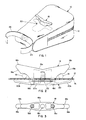
- the embodiment shown in the drawings is integrated into a bicycle saddle bag 10, which is known per se .
- the bag 10 is made of a durable fabric and is of a generally wedge shape.
- a zipper 12 extends partway along each side and across the back.
- the bag is shaped by a moderately stiff liner 14 (Fig. 2) of a plastic foam sheet that is bent into a "U” and extends continuously along the bottom, front and top walls within the bag and is shaped in plan to conform to the borders of those walls.
- the bag 10 is attached to the two parallel metal side frame bars 16 (Fig. 2) of a bicycle saddle by the device of the present invention, which includes a cleat member 18 and a support member 20.
- the frame bars 16 are spaced apart laterally from each other by a dimension (“minor dimension”) that is less than the spacing along a line oblique to the lateral dimension (“major dimension”).
- the saddle frame bars 16 define an opening between them having a minor dimension and a major dimension that is substantially larger than the minor dimension and lies oblique to the minor dimension, that is, extends diagonally at a selected angle.
- the cleat member 18 and support member each have a medial portion 18a, 20a that spans the minor dimension of the opening and a leg portion 18b, 20b that extends out from each of the opposite ends of the medial portion for engagement with opposite sides (in this case, the top and bottom sides) of the saddle frame bars 16.
- the overall dimension between the outer ends of the leg portions 18b of the cleat member 18 is less than the major dimension of the opening formed by the frame bars 16 so that the cleat member 18 can be inserted between the frame bars from below and at an angle to its installed position and then rotated to align it with the minor dimension and engage the leg portions 18b, 20b with the seat frame bars 16.
- the medial portion 18a of the cleat member protrudes down between the frame bars, abuts the medial portion 20a of the support member and spans the space between the frame bars in the installed position (Fig. 2), thereby to keep the assembly (cleat, support and bag) from sliding from side to side and to define outwardly open slots in which the frame bars 16 are captured.
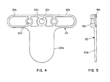
- the cleat member 18 and support member 20 are fastened together and to the bag 10 by a screw 22 that passes through a hole 20c in the support member 20 and threads into a hole 18c in the cleat member 18 and by pins 18d that project from the cleat member into holes 20d in the support member, which, of course, keep the bag 10, cleat member 18 and support member 20 from rotating relative to each other.
- the cleat member and support member are preferably molded from a rigid polymeric material. To save material and keep the weight low, the surfaces that face each other and the interior of the bag have recesses (see Figs. 2 to 5).
- the support member has a plate portion 20e that stabilizes the connection of the bag 20 to the cleat member and support member against rocking in the front-to-rear direction.
- each leg portion 18b of the cleat member 18 has a cam surface 18e that diverges obliquely away from the bag wall and from the longitudinal axis of the bag. If the user does not begin installation by pushing the bag up against the frame bars 16, the rotation of the bag (and the attachment device) will bring the cam surfaces 18e into engagement with the bars, and the cam surfaces will draw the bag up against the bars and help guide the bars into the receiving spaces between the leg portions 18b, 20b of the cleat member and support member.
- the attachment device further includes a hook cloth strap 24 and a loop cloth strap 26 stitched to the front end of the bag. These straps are taken along either side of the saddle post and joined in front of the post. The straps keep the bag from rotating or translating relative to the saddle frame.
- the invention has been described above and shown in the drawings as applied to a saddle bag accessory.
- the invention is also applicable to carrier bags that rest on top of the platform of front and rear carrier racks.
- the cleat members can extend down from the undersides of the bags and engage spaced-apart elements of the platform, such as the side rails.
- a strap or latch can provide the third attachment point against rotation and longitudinal displacement.
- Another application of the present invention is in a water bottle holder for attachment under the saddle.
- the support member can be attached to or form part of a cage for a spare water bottle.
- the invention is also useful in special brackets and holders for tools, spare tire tubes, or other articles, again by designing the support member appropriately for the special use.
- the cleat member and support member can be molded in one piece.
- a common characteristic of the uses of the invention is that the elements of the bicycle forming the opening that receives the cleat member have surfaces that are engaged in the slots formed by the leg portions of the cleat member and support member that are substantially planar, so that the attachment device can be inserted into the opening in one orientation and rotated in a plane to the attached position. Also, if the accessory is not stably supported by such elements, the leg portions of the support member may be made wide enough to impart stability by forming stabilizing plate-like portions.
- the third attachment point of the device may be associated directly with the support member, such as a strap or a latch affixed to a plate-like part of the support member spaced apart from the leg portions, or indirectly as part of the accessory being attached to the bicycle, as in the case of the straps 24 and 26 in the embodiment, or as a strap or latch attached to the bicycle.
Landscapes
- Engineering & Computer Science (AREA)
- Mechanical Engineering (AREA)
- Motorcycle And Bicycle Frame (AREA)
- Steering Devices For Bicycles And Motorcycles (AREA)
- Professional, Industrial, Or Sporting Protective Garments (AREA)
- Passenger Equipment (AREA)
- Purses, Travelling Bags, Baskets, Or Suitcases (AREA)
- Axle Suspensions And Sidecars For Cycles (AREA)
- Connection Of Plates (AREA)
- Snaps, Bayonet Connections, Set Pins, And Snap Rings (AREA)
Abstract
Description
- The present invention is a device for mounting an accessory on a bicycle.
- A wide variety of accessories are used by bicyclists to carry things they want to have with them during their rides. For example, bicyclists who ride long distances for recreation, touring, or racing carry one or more water bottles. Nearly all bicyclists equip their bikes with a saddle bag for carrying small articles, such as a wallet, money, keys, tools, a spare tire inner tube, an extra water bottle and food. For recreational bicycling and touring there are carrier bags that fit on the top of front or rear carrier racks.
- Nearly all carrier bags for bicycle saddles that are currently on the market are attached by two hook and loop cloth (Velcro®) straps that are wrapped around the two frame bars of the saddle and a third hook and loop cloth strap that is wrapped around the saddle post. Similarly, hook and loop cloth straps wrapped around the side rails of the platforms of carrier racks constitute the most common way of attaching carrier bags on the tops of rack platforms. These widely used hook and loop cloth attachment systems, though quite satisfactory, are a little tedious to use. The user has to form each loop around the frame bar or side rail and press it home. With saddle bags the user must hold the bag with one hand and complete the two side loop attachments with the other hand in a relatively small space up under the saddle. Also, the tenacity of the hook and loop cloth diminishes as the material wears with normal use.
- An object of the present invention is to provide a device for attaching various bicycle accessories to the bicycle in a manner that is very simple to use, provides a very secure attachment and is highly durable. The device makes use of two spaced-apart elements that are affixed to the bicycle and define an opening between them. Such elements include the frame bars of saddles and the platform rails of carrier racks.
- The present invention is a device for attaching an accessory to first and second spaced-apart elements affixed to a bicycle and defining an opening between them, which opening has a minor dimension and a major dimension. The device comprises a support member and a cleat member, each of which has a medial portion adapted to span the minor dimension of the opening and a leg portion extending out from each of the opposite ends of the medial portion for engagement with opposite sides of a respective one of said elements. The overall dimension between the outer ends of the leg portions of the cleat member is less than the major dimension of the opening so that the cleat member can be inserted in the opening by aligning it with the major dimension of the opening and then repositioned to align it with the minor dimension and engage the leg portions with the bicycle elements. The invention further includes a component for fastening the cleat member to the support member, a component for fastening the accessory to the support member, and a component for releasably connecting the support member to a third element affixed to the bicycle to prevent the cleat member and support member from rotating or translating relative to the first and second elements.
- In preferred forms of the invention, the elements defining the opening have opposite sides forming a plane, and the surfaces of the leg portions of the support member that engage the elements are also planar, whereby rotation of the cleat member and support member can occur without cocking or strain. Each leg portion of the cleat member may have a camming surface adapted to engage a respective element upon rotation from alignment with the major dimension to alignment with the minor dimension and to guide the leg portions of the cleat member and the support member into clamping engagements with the elements upon such rotation.
- The fastening means preferably comprises a single screw passing through a hole in the support member and threaded into the cleat member and at least one locating pin on the cleat member extending into a hole in the support member to prevent rotation of the cleat member relative to the support member.
- For a better understanding of the invention, reference may be made to the following description of an exemplary embodiment, taken in conjunction with the accompanying drawings.
-
- Fig. 1 is a front three-quarter pictorial view of the embodiment;
- Fig. 2 is a front elevational view of the embodiment;
- Fig. 3 is a bottom plan view of the cleat member;
- Fig. 4 is a bottom plan view of the support member; and
- Fig. 5 is a side elevational view of the cleat member.
- The embodiment shown in the drawings is integrated into a
bicycle saddle bag 10, which is known per se. Thebag 10 is made of a durable fabric and is of a generally wedge shape. Azipper 12 extends partway along each side and across the back. The bag is shaped by a moderately stiff liner 14 (Fig. 2) of a plastic foam sheet that is bent into a "U" and extends continuously along the bottom, front and top walls within the bag and is shaped in plan to conform to the borders of those walls. - The
bag 10 is attached to the two parallel metal side frame bars 16 (Fig. 2) of a bicycle saddle by the device of the present invention, which includes acleat member 18 and asupport member 20. Theframe bars 16 are spaced apart laterally from each other by a dimension ("minor dimension") that is less than the spacing along a line oblique to the lateral dimension ("major dimension"). Putting it another way, thesaddle frame bars 16 define an opening between them having a minor dimension and a major dimension that is substantially larger than the minor dimension and lies oblique to the minor dimension, that is, extends diagonally at a selected angle. Thecleat member 18 and support member each have amedial portion leg portion saddle frame bars 16. The overall dimension between the outer ends of theleg portions 18b of thecleat member 18 is less than the major dimension of the opening formed by theframe bars 16 so that thecleat member 18 can be inserted between the frame bars from below and at an angle to its installed position and then rotated to align it with the minor dimension and engage theleg portions seat frame bars 16. Themedial portion 18a of the cleat member protrudes down between the frame bars, abuts themedial portion 20a of the support member and spans the space between the frame bars in the installed position (Fig. 2), thereby to keep the assembly (cleat, support and bag) from sliding from side to side and to define outwardly open slots in which theframe bars 16 are captured. - The
cleat member 18 andsupport member 20 are fastened together and to thebag 10 by ascrew 22 that passes through ahole 20c in thesupport member 20 and threads into ahole 18c in thecleat member 18 and bypins 18d that project from the cleat member intoholes 20d in the support member, which, of course, keep thebag 10,cleat member 18 and supportmember 20 from rotating relative to each other. - The cleat member and support member are preferably molded from a rigid polymeric material. To save material and keep the weight low, the surfaces that face each other and the interior of the bag have recesses (see Figs. 2 to 5). The support member has a
plate portion 20e that stabilizes the connection of thebag 20 to the cleat member and support member against rocking in the front-to-rear direction. - To facilitate installing the bag on the saddle frame bars, each
leg portion 18b of thecleat member 18 has acam surface 18e that diverges obliquely away from the bag wall and from the longitudinal axis of the bag. If the user does not begin installation by pushing the bag up against theframe bars 16, the rotation of the bag (and the attachment device) will bring thecam surfaces 18e into engagement with the bars, and the cam surfaces will draw the bag up against the bars and help guide the bars into the receiving spaces between theleg portions - In the embodiment, the attachment device further includes a
hook cloth strap 24 and aloop cloth strap 26 stitched to the front end of the bag. These straps are taken along either side of the saddle post and joined in front of the post. The straps keep the bag from rotating or translating relative to the saddle frame. - The invention has been described above and shown in the drawings as applied to a saddle bag accessory. The invention is also applicable to carrier bags that rest on top of the platform of front and rear carrier racks. The cleat members can extend down from the undersides of the bags and engage spaced-apart elements of the platform, such as the side rails. A strap or latch can provide the third attachment point against rotation and longitudinal displacement. Another application of the present invention is in a water bottle holder for attachment under the saddle. The support member can be attached to or form part of a cage for a spare water bottle. The invention is also useful in special brackets and holders for tools, spare tire tubes, or other articles, again by designing the support member appropriately for the special use. In water bottle holders and other special holders, the cleat member and support member can be molded in one piece.
- A common characteristic of the uses of the invention is that the elements of the bicycle forming the opening that receives the cleat member have surfaces that are engaged in the slots formed by the leg portions of the cleat member and support member that are substantially planar, so that the attachment device can be inserted into the opening in one orientation and rotated in a plane to the attached position. Also, if the accessory is not stably supported by such elements, the leg portions of the support member may be made wide enough to impart stability by forming stabilizing plate-like portions. The third attachment point of the device may be associated directly with the support member, such as a strap or a latch affixed to a plate-like part of the support member spaced apart from the leg portions, or indirectly as part of the accessory being attached to the bicycle, as in the case of the
straps
Claims (7)
Applications Claiming Priority (2)
| Application Number | Priority Date | Filing Date | Title |
|---|---|---|---|
| US40643089A | 1989-09-12 | 1989-09-12 | |
| US406430 | 1989-09-12 |
Publications (3)
| Publication Number | Publication Date |
|---|---|
| EP0417419A2 true EP0417419A2 (en) | 1991-03-20 |
| EP0417419A3 EP0417419A3 (en) | 1991-05-08 |
| EP0417419B1 EP0417419B1 (en) | 1994-11-09 |
Family
ID=23607956
Family Applications (1)
| Application Number | Title | Priority Date | Filing Date |
|---|---|---|---|
| EP90112968A Expired - Lifetime EP0417419B1 (en) | 1989-09-12 | 1990-07-06 | Mounting device for bicycle accessories |
Country Status (5)
| Country | Link |
|---|---|
| EP (1) | EP0417419B1 (en) |
| JP (1) | JPH0399990A (en) |
| AT (1) | ATE113913T1 (en) |
| DE (1) | DE69014033T2 (en) |
| ES (1) | ES2063867T3 (en) |
Cited By (4)
| Publication number | Priority date | Publication date | Assignee | Title |
|---|---|---|---|---|
| EP0523505A1 (en) * | 1991-07-15 | 1993-01-20 | Deuter Sport Und Leder Gmbh | Attachment means for a pannier |
| EP0578214A1 (en) * | 1992-07-08 | 1994-01-12 | Dlugos, Gabriele | Saddle bag for bicycles |
| US9743732B1 (en) | 2013-11-05 | 2017-08-29 | John T. Busby | Safety eyeglass case and mounting brackets |
| WO2020224733A1 (en) * | 2019-05-06 | 2020-11-12 | Joggler Aps | Transport system |
Families Citing this family (2)
| Publication number | Priority date | Publication date | Assignee | Title |
|---|---|---|---|---|
| DE4413920B4 (en) * | 1993-06-18 | 2004-07-15 | Carl Zeiss | Insert for viewing opening of a drape and drape with such an insert and surgical microscope with such drape and insert |
| JP4867304B2 (en) * | 2005-11-16 | 2012-02-01 | 井関農機株式会社 | Soot separating apparatus and soot separating method |
Citations (3)
| Publication number | Priority date | Publication date | Assignee | Title |
|---|---|---|---|---|
| CH234492A (en) * | 1944-05-12 | 1944-09-30 | Sigg Wilhelm | Device for securing objects to be transported on bicycle racks. |
| DE2846347A1 (en) * | 1978-10-25 | 1980-04-30 | Willy Nitzsche | Lockable container for bicycle carrier - includes internal fasteners and several tamperproof clamps |
| US4566617A (en) * | 1984-07-13 | 1986-01-28 | Jackson W S | Seat pack assembly |
-
1990
- 1990-07-06 ES ES90112968T patent/ES2063867T3/en not_active Expired - Lifetime
- 1990-07-06 AT AT90112968T patent/ATE113913T1/en not_active IP Right Cessation
- 1990-07-06 EP EP90112968A patent/EP0417419B1/en not_active Expired - Lifetime
- 1990-07-06 DE DE69014033T patent/DE69014033T2/en not_active Expired - Fee Related
- 1990-07-27 JP JP2201046A patent/JPH0399990A/en active Pending
Patent Citations (3)
| Publication number | Priority date | Publication date | Assignee | Title |
|---|---|---|---|---|
| CH234492A (en) * | 1944-05-12 | 1944-09-30 | Sigg Wilhelm | Device for securing objects to be transported on bicycle racks. |
| DE2846347A1 (en) * | 1978-10-25 | 1980-04-30 | Willy Nitzsche | Lockable container for bicycle carrier - includes internal fasteners and several tamperproof clamps |
| US4566617A (en) * | 1984-07-13 | 1986-01-28 | Jackson W S | Seat pack assembly |
Cited By (4)
| Publication number | Priority date | Publication date | Assignee | Title |
|---|---|---|---|---|
| EP0523505A1 (en) * | 1991-07-15 | 1993-01-20 | Deuter Sport Und Leder Gmbh | Attachment means for a pannier |
| EP0578214A1 (en) * | 1992-07-08 | 1994-01-12 | Dlugos, Gabriele | Saddle bag for bicycles |
| US9743732B1 (en) | 2013-11-05 | 2017-08-29 | John T. Busby | Safety eyeglass case and mounting brackets |
| WO2020224733A1 (en) * | 2019-05-06 | 2020-11-12 | Joggler Aps | Transport system |
Also Published As
| Publication number | Publication date |
|---|---|
| DE69014033T2 (en) | 1995-03-23 |
| EP0417419B1 (en) | 1994-11-09 |
| ES2063867T3 (en) | 1995-01-16 |
| EP0417419A3 (en) | 1991-05-08 |
| DE69014033D1 (en) | 1994-12-15 |
| ATE113913T1 (en) | 1994-11-15 |
| JPH0399990A (en) | 1991-04-25 |
Similar Documents
| Publication | Publication Date | Title |
|---|---|---|
| US5127563A (en) | Mounting device for bicycle accessories | |
| US5593126A (en) | Seat post bag clip | |
| US4798318A (en) | Carrier bag assembly for bicycle handlebars | |
| US4353490A (en) | Pannier mounting system for cycles | |
| US5667117A (en) | Fastening device | |
| US6315182B1 (en) | Cellular phone pouch assembly adapted to be mounted on a bar | |
| CA2169574C (en) | Single arm holder and bracket for bicycle rack | |
| US5282555A (en) | Stabilization assembly for bicycle racks | |
| US4562944A (en) | Adjustable connections on cycle rear carrier | |
| US7503573B2 (en) | Skateboard carrier for bicycle | |
| US4174795A (en) | Pannier mounting arrangement for cycles | |
| US4577786A (en) | Pannier bag having a clamping device with locking member | |
| US20060061156A1 (en) | Quick-connect structure for bicycle saddle | |
| US4258870A (en) | Pannier bags and device for attachment to bicycle | |
| EP1056637B1 (en) | Auxiliary bicycle seat | |
| US6422443B1 (en) | Bicycle carrier with unitary frame and leveling indicators | |
| EP1318941B1 (en) | Bicycle lock holder | |
| US5649657A (en) | Article carrier assembly for cycles | |
| US4256322A (en) | Combined carrying and locking device for a cycle | |
| US4971343A (en) | Shopping cart having an infant carrier and an infant carrier therefor | |
| US6966471B1 (en) | Folding luggage rack for motorcycles | |
| EP0417419A2 (en) | Mounting device for bicycle accessories | |
| US4418850A (en) | Pannier and mounting arrangement for cycles | |
| NO862882L (en) | BACKPACK. | |
| US5551609A (en) | Bicycle rack with integral lock holder |
Legal Events
| Date | Code | Title | Description |
|---|---|---|---|
| PUAI | Public reference made under article 153(3) epc to a published international application that has entered the european phase |
Free format text: ORIGINAL CODE: 0009012 |
|
| PUAL | Search report despatched |
Free format text: ORIGINAL CODE: 0009013 |
|
| AK | Designated contracting states |
Kind code of ref document: A2 Designated state(s): AT BE CH DE DK ES FR GB GR IT LI NL SE |
|
| AK | Designated contracting states |
Kind code of ref document: A3 Designated state(s): AT BE CH DE DK ES FR GB GR IT LI NL SE |
|
| 17P | Request for examination filed |
Effective date: 19911015 |
|
| 17Q | First examination report despatched |
Effective date: 19930609 |
|
| GRAA | (expected) grant |
Free format text: ORIGINAL CODE: 0009210 |
|
| AK | Designated contracting states |
Kind code of ref document: B1 Designated state(s): AT BE CH DE DK ES FR GB GR IT LI NL SE |
|
| PG25 | Lapsed in a contracting state [announced via postgrant information from national office to epo] |
Ref country code: NL Effective date: 19941109 Ref country code: LI Effective date: 19941109 Ref country code: GR Free format text: LAPSE BECAUSE OF FAILURE TO SUBMIT A TRANSLATION OF THE DESCRIPTION OR TO PAY THE FEE WITHIN THE PRESCRIBED TIME-LIMIT Effective date: 19941109 Ref country code: DK Effective date: 19941109 Ref country code: CH Effective date: 19941109 Ref country code: BE Effective date: 19941109 Ref country code: AT Effective date: 19941109 |
|
| REF | Corresponds to: |
Ref document number: 113913 Country of ref document: AT Date of ref document: 19941115 Kind code of ref document: T |
|
| REF | Corresponds to: |
Ref document number: 69014033 Country of ref document: DE Date of ref document: 19941215 |
|
| REG | Reference to a national code |
Ref country code: ES Ref legal event code: FG2A Ref document number: 2063867 Country of ref document: ES Kind code of ref document: T3 |
|
| ITF | It: translation for a ep patent filed | ||
| PG25 | Lapsed in a contracting state [announced via postgrant information from national office to epo] |
Ref country code: SE Effective date: 19950209 |
|
| REG | Reference to a national code |
Ref country code: CH Ref legal event code: PL |
|
| ET | Fr: translation filed | ||
| NLV1 | Nl: lapsed or annulled due to failure to fulfill the requirements of art. 29p and 29m of the patents act | ||
| PLBE | No opposition filed within time limit |
Free format text: ORIGINAL CODE: 0009261 |
|
| STAA | Information on the status of an ep patent application or granted ep patent |
Free format text: STATUS: NO OPPOSITION FILED WITHIN TIME LIMIT |
|
| 26N | No opposition filed | ||
| PGFP | Annual fee paid to national office [announced via postgrant information from national office to epo] |
Ref country code: FR Payment date: 19970620 Year of fee payment: 8 |
|
| PGFP | Annual fee paid to national office [announced via postgrant information from national office to epo] |
Ref country code: DE Payment date: 19970624 Year of fee payment: 8 |
|
| PGFP | Annual fee paid to national office [announced via postgrant information from national office to epo] |
Ref country code: GB Payment date: 19970626 Year of fee payment: 8 |
|
| PGFP | Annual fee paid to national office [announced via postgrant information from national office to epo] |
Ref country code: ES Payment date: 19970717 Year of fee payment: 8 |
|
| PG25 | Lapsed in a contracting state [announced via postgrant information from national office to epo] |
Ref country code: GB Free format text: LAPSE BECAUSE OF NON-PAYMENT OF DUE FEES Effective date: 19980706 |
|
| PG25 | Lapsed in a contracting state [announced via postgrant information from national office to epo] |
Ref country code: ES Free format text: LAPSE BECAUSE OF THE APPLICANT RENOUNCES Effective date: 19980707 |
|
| GBPC | Gb: european patent ceased through non-payment of renewal fee |
Effective date: 19980706 |
|
| PG25 | Lapsed in a contracting state [announced via postgrant information from national office to epo] |
Ref country code: FR Free format text: LAPSE BECAUSE OF NON-PAYMENT OF DUE FEES Effective date: 19990331 |
|
| PG25 | Lapsed in a contracting state [announced via postgrant information from national office to epo] |
Ref country code: DE Free format text: LAPSE BECAUSE OF NON-PAYMENT OF DUE FEES Effective date: 19990501 |
|
| REG | Reference to a national code |
Ref country code: FR Ref legal event code: ST |
|
| REG | Reference to a national code |
Ref country code: ES Ref legal event code: FD2A Effective date: 20001009 |
|
| PG25 | Lapsed in a contracting state [announced via postgrant information from national office to epo] |
Ref country code: IT Free format text: LAPSE BECAUSE OF NON-PAYMENT OF DUE FEES;WARNING: LAPSES OF ITALIAN PATENTS WITH EFFECTIVE DATE BEFORE 2007 MAY HAVE OCCURRED AT ANY TIME BEFORE 2007. THE CORRECT EFFECTIVE DATE MAY BE DIFFERENT FROM THE ONE RECORDED. Effective date: 20050706 |