EP0417275B1 - Automatic speed change method for dump truck for construction machine - Google Patents
Automatic speed change method for dump truck for construction machine Download PDFInfo
- Publication number
- EP0417275B1 EP0417275B1 EP88901457A EP88901457A EP0417275B1 EP 0417275 B1 EP0417275 B1 EP 0417275B1 EP 88901457 A EP88901457 A EP 88901457A EP 88901457 A EP88901457 A EP 88901457A EP 0417275 B1 EP0417275 B1 EP 0417275B1
- Authority
- EP
- European Patent Office
- Prior art keywords
- speed
- engine
- vehicle
- speed change
- power transmission
- Prior art date
- Legal status (The legal status is an assumption and is not a legal conclusion. Google has not performed a legal analysis and makes no representation as to the accuracy of the status listed.)
- Expired - Lifetime
Links
Images


Classifications
-
- B—PERFORMING OPERATIONS; TRANSPORTING
- B60—VEHICLES IN GENERAL
- B60W—CONJOINT CONTROL OF VEHICLE SUB-UNITS OF DIFFERENT TYPE OR DIFFERENT FUNCTION; CONTROL SYSTEMS SPECIALLY ADAPTED FOR HYBRID VEHICLES; ROAD VEHICLE DRIVE CONTROL SYSTEMS FOR PURPOSES NOT RELATED TO THE CONTROL OF A PARTICULAR SUB-UNIT
- B60W10/00—Conjoint control of vehicle sub-units of different type or different function
- B60W10/04—Conjoint control of vehicle sub-units of different type or different function including control of propulsion units
- B60W10/06—Conjoint control of vehicle sub-units of different type or different function including control of propulsion units including control of combustion engines
-
- B—PERFORMING OPERATIONS; TRANSPORTING
- B60—VEHICLES IN GENERAL
- B60W—CONJOINT CONTROL OF VEHICLE SUB-UNITS OF DIFFERENT TYPE OR DIFFERENT FUNCTION; CONTROL SYSTEMS SPECIALLY ADAPTED FOR HYBRID VEHICLES; ROAD VEHICLE DRIVE CONTROL SYSTEMS FOR PURPOSES NOT RELATED TO THE CONTROL OF A PARTICULAR SUB-UNIT
- B60W10/00—Conjoint control of vehicle sub-units of different type or different function
- B60W10/04—Conjoint control of vehicle sub-units of different type or different function including control of propulsion units
-
- B—PERFORMING OPERATIONS; TRANSPORTING
- B60—VEHICLES IN GENERAL
- B60W—CONJOINT CONTROL OF VEHICLE SUB-UNITS OF DIFFERENT TYPE OR DIFFERENT FUNCTION; CONTROL SYSTEMS SPECIALLY ADAPTED FOR HYBRID VEHICLES; ROAD VEHICLE DRIVE CONTROL SYSTEMS FOR PURPOSES NOT RELATED TO THE CONTROL OF A PARTICULAR SUB-UNIT
- B60W10/00—Conjoint control of vehicle sub-units of different type or different function
- B60W10/10—Conjoint control of vehicle sub-units of different type or different function including control of change-speed gearings
- B60W10/11—Stepped gearings
- B60W10/115—Stepped gearings with planetary gears
-
- B—PERFORMING OPERATIONS; TRANSPORTING
- B60—VEHICLES IN GENERAL
- B60W—CONJOINT CONTROL OF VEHICLE SUB-UNITS OF DIFFERENT TYPE OR DIFFERENT FUNCTION; CONTROL SYSTEMS SPECIALLY ADAPTED FOR HYBRID VEHICLES; ROAD VEHICLE DRIVE CONTROL SYSTEMS FOR PURPOSES NOT RELATED TO THE CONTROL OF A PARTICULAR SUB-UNIT
- B60W30/00—Purposes of road vehicle drive control systems not related to the control of a particular sub-unit, e.g. of systems using conjoint control of vehicle sub-units, or advanced driver assistance systems for ensuring comfort, stability and safety or drive control systems for propelling or retarding the vehicle
- B60W30/18—Propelling the vehicle
- B60W30/1819—Propulsion control with control means using analogue circuits, relays or mechanical links
-
- B—PERFORMING OPERATIONS; TRANSPORTING
- B60—VEHICLES IN GENERAL
- B60W—CONJOINT CONTROL OF VEHICLE SUB-UNITS OF DIFFERENT TYPE OR DIFFERENT FUNCTION; CONTROL SYSTEMS SPECIALLY ADAPTED FOR HYBRID VEHICLES; ROAD VEHICLE DRIVE CONTROL SYSTEMS FOR PURPOSES NOT RELATED TO THE CONTROL OF A PARTICULAR SUB-UNIT
- B60W30/00—Purposes of road vehicle drive control systems not related to the control of a particular sub-unit, e.g. of systems using conjoint control of vehicle sub-units, or advanced driver assistance systems for ensuring comfort, stability and safety or drive control systems for propelling or retarding the vehicle
- B60W30/18—Propelling the vehicle
- B60W30/19—Improvement of gear change, e.g. by synchronisation or smoothing gear shift
-
- F—MECHANICAL ENGINEERING; LIGHTING; HEATING; WEAPONS; BLASTING
- F16—ENGINEERING ELEMENTS AND UNITS; GENERAL MEASURES FOR PRODUCING AND MAINTAINING EFFECTIVE FUNCTIONING OF MACHINES OR INSTALLATIONS; THERMAL INSULATION IN GENERAL
- F16H—GEARING
- F16H61/00—Control functions within control units of change-speed- or reversing-gearings for conveying rotary motion ; Control of exclusively fluid gearing, friction gearing, gearings with endless flexible members or other particular types of gearing
- F16H61/02—Control functions within control units of change-speed- or reversing-gearings for conveying rotary motion ; Control of exclusively fluid gearing, friction gearing, gearings with endless flexible members or other particular types of gearing characterised by the signals used
- F16H61/0202—Control functions within control units of change-speed- or reversing-gearings for conveying rotary motion ; Control of exclusively fluid gearing, friction gearing, gearings with endless flexible members or other particular types of gearing characterised by the signals used the signals being electric
- F16H61/0204—Control functions within control units of change-speed- or reversing-gearings for conveying rotary motion ; Control of exclusively fluid gearing, friction gearing, gearings with endless flexible members or other particular types of gearing characterised by the signals used the signals being electric for gearshift control, e.g. control functions for performing shifting or generation of shift signal
- F16H61/0213—Control functions within control units of change-speed- or reversing-gearings for conveying rotary motion ; Control of exclusively fluid gearing, friction gearing, gearings with endless flexible members or other particular types of gearing characterised by the signals used the signals being electric for gearshift control, e.g. control functions for performing shifting or generation of shift signal characterised by the method for generating shift signals
-
- F—MECHANICAL ENGINEERING; LIGHTING; HEATING; WEAPONS; BLASTING
- F16—ENGINEERING ELEMENTS AND UNITS; GENERAL MEASURES FOR PRODUCING AND MAINTAINING EFFECTIVE FUNCTIONING OF MACHINES OR INSTALLATIONS; THERMAL INSULATION IN GENERAL
- F16H—GEARING
- F16H61/00—Control functions within control units of change-speed- or reversing-gearings for conveying rotary motion ; Control of exclusively fluid gearing, friction gearing, gearings with endless flexible members or other particular types of gearing
- F16H61/04—Smoothing ratio shift
- F16H61/0437—Smoothing ratio shift by using electrical signals
-
- F—MECHANICAL ENGINEERING; LIGHTING; HEATING; WEAPONS; BLASTING
- F16—ENGINEERING ELEMENTS AND UNITS; GENERAL MEASURES FOR PRODUCING AND MAINTAINING EFFECTIVE FUNCTIONING OF MACHINES OR INSTALLATIONS; THERMAL INSULATION IN GENERAL
- F16H—GEARING
- F16H61/00—Control functions within control units of change-speed- or reversing-gearings for conveying rotary motion ; Control of exclusively fluid gearing, friction gearing, gearings with endless flexible members or other particular types of gearing
- F16H61/04—Smoothing ratio shift
- F16H61/06—Smoothing ratio shift by controlling rate of change of fluid pressure
- F16H61/061—Smoothing ratio shift by controlling rate of change of fluid pressure using electric control means
-
- F—MECHANICAL ENGINEERING; LIGHTING; HEATING; WEAPONS; BLASTING
- F16—ENGINEERING ELEMENTS AND UNITS; GENERAL MEASURES FOR PRODUCING AND MAINTAINING EFFECTIVE FUNCTIONING OF MACHINES OR INSTALLATIONS; THERMAL INSULATION IN GENERAL
- F16H—GEARING
- F16H61/00—Control functions within control units of change-speed- or reversing-gearings for conveying rotary motion ; Control of exclusively fluid gearing, friction gearing, gearings with endless flexible members or other particular types of gearing
- F16H61/14—Control of torque converter lock-up clutches
- F16H61/143—Control of torque converter lock-up clutches using electric control means
-
- F—MECHANICAL ENGINEERING; LIGHTING; HEATING; WEAPONS; BLASTING
- F16—ENGINEERING ELEMENTS AND UNITS; GENERAL MEASURES FOR PRODUCING AND MAINTAINING EFFECTIVE FUNCTIONING OF MACHINES OR INSTALLATIONS; THERMAL INSULATION IN GENERAL
- F16H—GEARING
- F16H63/00—Control outputs from the control unit to change-speed- or reversing-gearings for conveying rotary motion or to other devices than the final output mechanism
- F16H63/40—Control outputs from the control unit to change-speed- or reversing-gearings for conveying rotary motion or to other devices than the final output mechanism comprising signals other than signals for actuating the final output mechanisms
- F16H63/50—Signals to an engine or motor
- F16H63/502—Signals to an engine or motor for smoothing gear shifts
-
- B—PERFORMING OPERATIONS; TRANSPORTING
- B60—VEHICLES IN GENERAL
- B60W—CONJOINT CONTROL OF VEHICLE SUB-UNITS OF DIFFERENT TYPE OR DIFFERENT FUNCTION; CONTROL SYSTEMS SPECIALLY ADAPTED FOR HYBRID VEHICLES; ROAD VEHICLE DRIVE CONTROL SYSTEMS FOR PURPOSES NOT RELATED TO THE CONTROL OF A PARTICULAR SUB-UNIT
- B60W2530/00—Input parameters relating to vehicle conditions or values, not covered by groups B60W2510/00 or B60W2520/00
- B60W2530/16—Driving resistance
-
- B—PERFORMING OPERATIONS; TRANSPORTING
- B60—VEHICLES IN GENERAL
- B60Y—INDEXING SCHEME RELATING TO ASPECTS CROSS-CUTTING VEHICLE TECHNOLOGY
- B60Y2200/00—Type of vehicle
- B60Y2200/10—Road Vehicles
- B60Y2200/14—Trucks; Load vehicles, Busses
-
- F—MECHANICAL ENGINEERING; LIGHTING; HEATING; WEAPONS; BLASTING
- F16—ENGINEERING ELEMENTS AND UNITS; GENERAL MEASURES FOR PRODUCING AND MAINTAINING EFFECTIVE FUNCTIONING OF MACHINES OR INSTALLATIONS; THERMAL INSULATION IN GENERAL
- F16H—GEARING
- F16H59/00—Control inputs to control units of change-speed-, or reversing-gearings for conveying rotary motion
- F16H59/74—Inputs being a function of engine parameters
- F16H2059/743—Inputs being a function of engine parameters using engine performance or power for control of gearing
-
- F—MECHANICAL ENGINEERING; LIGHTING; HEATING; WEAPONS; BLASTING
- F16—ENGINEERING ELEMENTS AND UNITS; GENERAL MEASURES FOR PRODUCING AND MAINTAINING EFFECTIVE FUNCTIONING OF MACHINES OR INSTALLATIONS; THERMAL INSULATION IN GENERAL
- F16H—GEARING
- F16H61/00—Control functions within control units of change-speed- or reversing-gearings for conveying rotary motion ; Control of exclusively fluid gearing, friction gearing, gearings with endless flexible members or other particular types of gearing
- F16H2061/0012—Transmission control for optimising power output of driveline
-
- F—MECHANICAL ENGINEERING; LIGHTING; HEATING; WEAPONS; BLASTING
- F16—ENGINEERING ELEMENTS AND UNITS; GENERAL MEASURES FOR PRODUCING AND MAINTAINING EFFECTIVE FUNCTIONING OF MACHINES OR INSTALLATIONS; THERMAL INSULATION IN GENERAL
- F16H—GEARING
- F16H61/00—Control functions within control units of change-speed- or reversing-gearings for conveying rotary motion ; Control of exclusively fluid gearing, friction gearing, gearings with endless flexible members or other particular types of gearing
- F16H2061/0015—Transmission control for optimising fuel consumptions
-
- F—MECHANICAL ENGINEERING; LIGHTING; HEATING; WEAPONS; BLASTING
- F16—ENGINEERING ELEMENTS AND UNITS; GENERAL MEASURES FOR PRODUCING AND MAINTAINING EFFECTIVE FUNCTIONING OF MACHINES OR INSTALLATIONS; THERMAL INSULATION IN GENERAL
- F16H—GEARING
- F16H61/00—Control functions within control units of change-speed- or reversing-gearings for conveying rotary motion ; Control of exclusively fluid gearing, friction gearing, gearings with endless flexible members or other particular types of gearing
- F16H61/02—Control functions within control units of change-speed- or reversing-gearings for conveying rotary motion ; Control of exclusively fluid gearing, friction gearing, gearings with endless flexible members or other particular types of gearing characterised by the signals used
- F16H61/0202—Control functions within control units of change-speed- or reversing-gearings for conveying rotary motion ; Control of exclusively fluid gearing, friction gearing, gearings with endless flexible members or other particular types of gearing characterised by the signals used the signals being electric
- F16H61/0204—Control functions within control units of change-speed- or reversing-gearings for conveying rotary motion ; Control of exclusively fluid gearing, friction gearing, gearings with endless flexible members or other particular types of gearing characterised by the signals used the signals being electric for gearshift control, e.g. control functions for performing shifting or generation of shift signal
- F16H61/0206—Layout of electro-hydraulic control circuits, e.g. arrangement of valves
- F16H2061/0209—Layout of electro-hydraulic control circuits, e.g. arrangement of valves with independent solenoid valves modulating the pressure individually for each clutch or brake
-
- F—MECHANICAL ENGINEERING; LIGHTING; HEATING; WEAPONS; BLASTING
- F16—ENGINEERING ELEMENTS AND UNITS; GENERAL MEASURES FOR PRODUCING AND MAINTAINING EFFECTIVE FUNCTIONING OF MACHINES OR INSTALLATIONS; THERMAL INSULATION IN GENERAL
- F16H—GEARING
- F16H61/00—Control functions within control units of change-speed- or reversing-gearings for conveying rotary motion ; Control of exclusively fluid gearing, friction gearing, gearings with endless flexible members or other particular types of gearing
- F16H61/02—Control functions within control units of change-speed- or reversing-gearings for conveying rotary motion ; Control of exclusively fluid gearing, friction gearing, gearings with endless flexible members or other particular types of gearing characterised by the signals used
- F16H61/0202—Control functions within control units of change-speed- or reversing-gearings for conveying rotary motion ; Control of exclusively fluid gearing, friction gearing, gearings with endless flexible members or other particular types of gearing characterised by the signals used the signals being electric
- F16H61/0251—Elements specially adapted for electric control units, e.g. valves for converting electrical signals to fluid signals
- F16H2061/026—On-off solenoid valve
-
- F—MECHANICAL ENGINEERING; LIGHTING; HEATING; WEAPONS; BLASTING
- F16—ENGINEERING ELEMENTS AND UNITS; GENERAL MEASURES FOR PRODUCING AND MAINTAINING EFFECTIVE FUNCTIONING OF MACHINES OR INSTALLATIONS; THERMAL INSULATION IN GENERAL
- F16H—GEARING
- F16H2302/00—Determining the way or trajectory to new ratio, e.g. by determining speed, torque or time parameters for shift transition
- F16H2302/04—Determining a modus for shifting
-
- F—MECHANICAL ENGINEERING; LIGHTING; HEATING; WEAPONS; BLASTING
- F16—ENGINEERING ELEMENTS AND UNITS; GENERAL MEASURES FOR PRODUCING AND MAINTAINING EFFECTIVE FUNCTIONING OF MACHINES OR INSTALLATIONS; THERMAL INSULATION IN GENERAL
- F16H—GEARING
- F16H2306/00—Shifting
- F16H2306/40—Shifting activities
- F16H2306/44—Removing torque from current gears
-
- F—MECHANICAL ENGINEERING; LIGHTING; HEATING; WEAPONS; BLASTING
- F16—ENGINEERING ELEMENTS AND UNITS; GENERAL MEASURES FOR PRODUCING AND MAINTAINING EFFECTIVE FUNCTIONING OF MACHINES OR INSTALLATIONS; THERMAL INSULATION IN GENERAL
- F16H—GEARING
- F16H2306/00—Shifting
- F16H2306/40—Shifting activities
- F16H2306/54—Synchronizing engine speed to transmission input speed
-
- F—MECHANICAL ENGINEERING; LIGHTING; HEATING; WEAPONS; BLASTING
- F16—ENGINEERING ELEMENTS AND UNITS; GENERAL MEASURES FOR PRODUCING AND MAINTAINING EFFECTIVE FUNCTIONING OF MACHINES OR INSTALLATIONS; THERMAL INSULATION IN GENERAL
- F16H—GEARING
- F16H59/00—Control inputs to control units of change-speed-, or reversing-gearings for conveying rotary motion
- F16H59/14—Inputs being a function of torque or torque demand
- F16H59/18—Inputs being a function of torque or torque demand dependent on the position of the accelerator pedal
-
- F—MECHANICAL ENGINEERING; LIGHTING; HEATING; WEAPONS; BLASTING
- F16—ENGINEERING ELEMENTS AND UNITS; GENERAL MEASURES FOR PRODUCING AND MAINTAINING EFFECTIVE FUNCTIONING OF MACHINES OR INSTALLATIONS; THERMAL INSULATION IN GENERAL
- F16H—GEARING
- F16H59/00—Control inputs to control units of change-speed-, or reversing-gearings for conveying rotary motion
- F16H59/48—Inputs being a function of acceleration
-
- F—MECHANICAL ENGINEERING; LIGHTING; HEATING; WEAPONS; BLASTING
- F16—ENGINEERING ELEMENTS AND UNITS; GENERAL MEASURES FOR PRODUCING AND MAINTAINING EFFECTIVE FUNCTIONING OF MACHINES OR INSTALLATIONS; THERMAL INSULATION IN GENERAL
- F16H—GEARING
- F16H59/00—Control inputs to control units of change-speed-, or reversing-gearings for conveying rotary motion
- F16H59/50—Inputs being a function of the status of the machine, e.g. position of doors or safety belts
- F16H59/52—Inputs being a function of the status of the machine, e.g. position of doors or safety belts dependent on the weight of the machine, e.g. change in weight resulting from passengers boarding a bus
-
- F—MECHANICAL ENGINEERING; LIGHTING; HEATING; WEAPONS; BLASTING
- F16—ENGINEERING ELEMENTS AND UNITS; GENERAL MEASURES FOR PRODUCING AND MAINTAINING EFFECTIVE FUNCTIONING OF MACHINES OR INSTALLATIONS; THERMAL INSULATION IN GENERAL
- F16H—GEARING
- F16H59/00—Control inputs to control units of change-speed-, or reversing-gearings for conveying rotary motion
- F16H59/50—Inputs being a function of the status of the machine, e.g. position of doors or safety belts
- F16H59/54—Inputs being a function of the status of the machine, e.g. position of doors or safety belts dependent on signals from the brakes, e.g. parking brakes
-
- F—MECHANICAL ENGINEERING; LIGHTING; HEATING; WEAPONS; BLASTING
- F16—ENGINEERING ELEMENTS AND UNITS; GENERAL MEASURES FOR PRODUCING AND MAINTAINING EFFECTIVE FUNCTIONING OF MACHINES OR INSTALLATIONS; THERMAL INSULATION IN GENERAL
- F16H—GEARING
- F16H61/00—Control functions within control units of change-speed- or reversing-gearings for conveying rotary motion ; Control of exclusively fluid gearing, friction gearing, gearings with endless flexible members or other particular types of gearing
- F16H61/0021—Generation or control of line pressure
-
- F—MECHANICAL ENGINEERING; LIGHTING; HEATING; WEAPONS; BLASTING
- F16—ENGINEERING ELEMENTS AND UNITS; GENERAL MEASURES FOR PRODUCING AND MAINTAINING EFFECTIVE FUNCTIONING OF MACHINES OR INSTALLATIONS; THERMAL INSULATION IN GENERAL
- F16H—GEARING
- F16H61/00—Control functions within control units of change-speed- or reversing-gearings for conveying rotary motion ; Control of exclusively fluid gearing, friction gearing, gearings with endless flexible members or other particular types of gearing
- F16H61/14—Control of torque converter lock-up clutches
-
- F—MECHANICAL ENGINEERING; LIGHTING; HEATING; WEAPONS; BLASTING
- F16—ENGINEERING ELEMENTS AND UNITS; GENERAL MEASURES FOR PRODUCING AND MAINTAINING EFFECTIVE FUNCTIONING OF MACHINES OR INSTALLATIONS; THERMAL INSULATION IN GENERAL
- F16H—GEARING
- F16H61/00—Control functions within control units of change-speed- or reversing-gearings for conveying rotary motion ; Control of exclusively fluid gearing, friction gearing, gearings with endless flexible members or other particular types of gearing
- F16H61/68—Control functions within control units of change-speed- or reversing-gearings for conveying rotary motion ; Control of exclusively fluid gearing, friction gearing, gearings with endless flexible members or other particular types of gearing specially adapted for stepped gearings
- F16H61/684—Control functions within control units of change-speed- or reversing-gearings for conveying rotary motion ; Control of exclusively fluid gearing, friction gearing, gearings with endless flexible members or other particular types of gearing specially adapted for stepped gearings without interruption of drive
- F16H61/686—Control functions within control units of change-speed- or reversing-gearings for conveying rotary motion ; Control of exclusively fluid gearing, friction gearing, gearings with endless flexible members or other particular types of gearing specially adapted for stepped gearings without interruption of drive with orbital gears
-
- F—MECHANICAL ENGINEERING; LIGHTING; HEATING; WEAPONS; BLASTING
- F16—ENGINEERING ELEMENTS AND UNITS; GENERAL MEASURES FOR PRODUCING AND MAINTAINING EFFECTIVE FUNCTIONING OF MACHINES OR INSTALLATIONS; THERMAL INSULATION IN GENERAL
- F16H—GEARING
- F16H61/00—Control functions within control units of change-speed- or reversing-gearings for conveying rotary motion ; Control of exclusively fluid gearing, friction gearing, gearings with endless flexible members or other particular types of gearing
- F16H61/70—Control functions within control units of change-speed- or reversing-gearings for conveying rotary motion ; Control of exclusively fluid gearing, friction gearing, gearings with endless flexible members or other particular types of gearing specially adapted for change-speed gearing in group arrangement, i.e. with separate change-speed gear trains arranged in series, e.g. range or overdrive-type gearing arrangements
-
- Y—GENERAL TAGGING OF NEW TECHNOLOGICAL DEVELOPMENTS; GENERAL TAGGING OF CROSS-SECTIONAL TECHNOLOGIES SPANNING OVER SEVERAL SECTIONS OF THE IPC; TECHNICAL SUBJECTS COVERED BY FORMER USPC CROSS-REFERENCE ART COLLECTIONS [XRACs] AND DIGESTS
- Y02—TECHNOLOGIES OR APPLICATIONS FOR MITIGATION OR ADAPTATION AGAINST CLIMATE CHANGE
- Y02T—CLIMATE CHANGE MITIGATION TECHNOLOGIES RELATED TO TRANSPORTATION
- Y02T10/00—Road transport of goods or passengers
- Y02T10/10—Internal combustion engine [ICE] based vehicles
- Y02T10/40—Engine management systems
-
- Y—GENERAL TAGGING OF NEW TECHNOLOGICAL DEVELOPMENTS; GENERAL TAGGING OF CROSS-SECTIONAL TECHNOLOGIES SPANNING OVER SEVERAL SECTIONS OF THE IPC; TECHNICAL SUBJECTS COVERED BY FORMER USPC CROSS-REFERENCE ART COLLECTIONS [XRACs] AND DIGESTS
- Y02—TECHNOLOGIES OR APPLICATIONS FOR MITIGATION OR ADAPTATION AGAINST CLIMATE CHANGE
- Y02T—CLIMATE CHANGE MITIGATION TECHNOLOGIES RELATED TO TRANSPORTATION
- Y02T10/00—Road transport of goods or passengers
- Y02T10/80—Technologies aiming to reduce greenhouse gasses emissions common to all road transportation technologies
- Y02T10/84—Data processing systems or methods, management, administration
Definitions
- This invention relates to a method for automatically changing the speed of a dump truck for use as a construction vehicle to a speed stage to be determined according to the operating condition of a power transmission or speed change gear thereof when the vehicle is running, and also relates to a method for operating the power transmission thereof.
- an automatic speed change method has been known wherein speed increasing points and speed decreasing points, i.e., speed change points are set on the basis of the relationship between the tractive force at each of speed stages of the power transmission when the engine is developing a maximum speed and the vehicle speed at that time, and the vehicle speed is detected from the number of revolutions of the engine etc., and when the thus detected vehicle speed exceeds a speed change point an automatic speed changeover to a next speed stage can be made.
- the arrangement is made such that speed change points f1 to f6 are set from the relationship between the tractive forces when the engine is developing a maximum output or power at forward first to seventh speeds F1 to F7 and running speeds of the vehicle, and when the vehicle speed exceeds each of the speed stages it is automatically changed over to a next speed stage.
- the maximum outputs or powers of the engines mounted on dump trucks for use as construction vehicles are not so high as those outputs required for them, and the weight of such vehicles in a loaded condition varies so much from that in an unloaded condition.
- the loadage and the gradient of roads on which vehicles run vary so much, the loading imposed on dump trucks for use as construction vehicles fluctuates largely, and also since it is difficult to detect the cargo on board and the gradient of roads with a high accuracy, it has been a common practice for dump trucks for use as construction vehicles to set speed change points which correspond always to the maximum output condition developed by the engine mounted on each of them, assuming cases where the loading imposed on them is high, and to run them with their engines developing maximum outputs.
- a control system for shiftable multi-speed hydraulically-operated power transmission and an electronic controller therein is disclosed.
- This control system discloses the features of the preamble parts of the independent claims.
- the control system is used in off-highway trucks as, for example, dump truck type vehicles.
- the output side of an engine is connected to a torque converter that is provided with a lock-up clutch.
- the output side of the torque converter is connected to the input side of a hydraulically-actuated power transmission having several hydraulically-operating shifting clutches therein.
- the output side of the power transmission is connected through a differential gear mechanism to wheels.
- the speed stages are selected under control of a built-in controller that receives electric signal information from a range selector switch, a detector means, a limit switch, and a rotary switch.
- the electronic controller receives the relevant signal information and provides control signals to effect automatic shifting, provided predetermined operating conditions are met.
- the speed signals, or shift points for upshift are adjustable or pre-settable for defining each speed range.
- the downshift points are also adjustable. Shifting takes places automatically upon achievement of transmission output speeds as scuttled for each range and indicated by a sensor. However, the highest speed range is selected by the operator and limits the transmission gear range regardless of higher transmission output speeds. If the operator moves the shift selector to a lower gear, the controller effects a lower gear downshift only when the correct speed is achieved by the torque converter turbine shaft, sensed by a respective sensor.
- the lock-up clutch is engaged and disengaged at pre-chosen speeds and is to be disengaged every time the transmission shifts. Thereafter, it must be re-engaged.
- the engine output when the vehicle is in a normal running condition, the engine output can be directly transmitted to the power transmission not through the intermediary of the torque converter thus reducing the power losses, and each time a speed change is made, the engine output is input or transmitted through the torque converter to the power transmission so that even if the revolving speed of the input shaft of the power transmission does not correspond to that of the output shaft the shocks due to speed changes can be absorbed by the torque converter to some degree thereby reducing the magnitude of such shocks.
- a speed change operational method wherein the supply of the pressurized fluid discharged by a pressurized fluid source to each of a plurality of speed stage clutches is controlled by each of the speed change valves associated therewith, and a progressive pressure increasing valve for gradually raising the fluid pressure in the pressurized fluid supply source is provided so that when supplying the fluid under pressure to a predetermined speed stage clutch the fluid pressure can be increased progressively to ensure smooth connection or engagement of the speed stage clutch without causing any shocks due to a speed change.
- Each of the speed stage clutches comprise a plurality of clutch plates which are rendered operative when they are urged into contact with one another and which are rendered inoperative when they are separated from one another. If the time required until the fluid pressure is increased to a predetermined value becomes longer, then each of the speed stage clutches can be engaged more smoothly. However, on the other hand, a longer time is required to make a speed change. Whilst, if the fluid pressure is increased to a predetermined value in a short time, then the time required for the speed change can be reduced, but on the other hand the speed stage clutch is engaged quickly thus causing a big shock due to the speed change. For this reason, the time required for increasing the fluid pressure to a predetermined value is usually set at one intermediate value of the two; that is to say, progressive pressure increasing characteristics are set by means of a progressive pressure increasing value.
- the loading imposed on the dump trucks for use as construction vehicles varies remarkably between loaded and unloaded conditions, and so they are driven repeatedly in heavy and light load conditions.
- a high load is applied to the power transmission so that the torque transmitted thereby becomes high
- a low load is applied to the transmission so that the torque transmitted thereby becomes low.
- the clutch plates tend to slip, while, if the torque is low the tendency of causing slip of the clutch plates is reduced. Therefore, if as mentioned above, the time required for increasing the fluid pressure to a predetermined value is constant and if the torque transmitted to the power transmission is high, the time required until the clutch plates are engaged completely without causing any slip to ensure satisfactory power transmission tends to increase thus increasing the time required for making a speed change. Whilst, in case the torque transmitted to the power transmission is low, it becomes possible to attain a condition that satisfactory power transmission can be made in a short time thereby increasing the tendency of occurrence of big shocks due to a speed change.
- the present invention has been contemplated in view of the above-mentioned circumstances, and has for its first object to provide a method for automatically changing the speed of a dump truck for use as a construction vehicle wherein the engine output can be utilized effectively and efficiently thereby reducing the fuel consumption.
- a dump truck for use as a construction vehicle has a vessel for loading earth and sand or rocks etc., which is mounted on the vehicle body thereof so as to be tilted freely, and left and right steering wheels and left and right drive wheels mounted through suspension cylinders on the vehicle body.
- the engine 10 has an output shaft 11 which is connected through a drive shaft 12 to a pump 14 for use with a torque converter 13, and a turbine 15 of the pump 14 is connected to an input shaft 17 of a power transmission or speed change gear 16. Further, there is provided a lock-up clutch 18 for connecting the turbine 15 of the pump 14.
- the power transmission 16 connects the input shaft 17 through a plurality of planetary gear mechanisms 19 to an output shaft 20 and is adapted to turn on and off a high speed clutch 21, a low speed clutch 22, first to fourth speed clutches 23 to 26, and a reversing clutch 27 so that a speed change to either one of the forward first to seventh speeds and a reversing speed, respectively.
- the output speed 20 of the power transmission or speed change gear 16 is connected through a differential gear 28 and final reduction gears 29 to the drive wheels 5,5.
- the above-mentioned clutches 21 to 27 are controlled, respectively, so as to be turned on and off by controlling the supply of fluid under pressure through the first to seventh speed change valves 31 to 37, respectively.
- the first to seventh speed change valves 31 to 37 are adapted to be changed over to their fluid supply positions when their solenoids 31a to 37a are energized and to assume their fluid supply cut-off positions when the solenoids are deenergized.
- the input side of the first and second speed change valves 31, 32 is provided with a modulation valve (inching valve) 38, and also the input side of the third to seventh speed change valves 33 to 37 is provided with another modulation valve (inching valve) 38 so that the pressure of the fluid under pressure supplied into each of the clutches 21 to 27 may be raised smoothly.
- the above-mentioned lock-up clutch 18 is supplied with the fluid under pressure discharged by a pump 39 through a lock-up changeover or control valve 40.
- the lock-up changeover valve 40 is adapted to be changed over to a fluid supply position when its solenoid 40a is energized so as to render the lock-up clutch 18 on or operative thus connecting the pump 14 and the turbine 15, and to assume a fluid supply cut-off position when the solenoid 40a is deenergized thereby rendering the lock-up clutch 18 off or inoperative.
- Fig. 4 is a schematic, overall explanatory view of a system for carrying out one embodiment of the automatic speed change method according to the present invention.
- the engine 10 is provided with a fuel injection pump 42a whose amount of fuel injection is controlled by an electronic control governor 42.
- the electronic control governor 42 is adapted to control the amount of fuel to be injected into the engine by reciprocating a rack rod 43 by the action of a hydraulic cylinder 44.
- the hydraulic cylinder 44 has a chamber 44a which is supplied through a control valve 45 with the fluid under pressure discharged by a pressurized fluid supply source, not shown, and there is provided a rack position detecting sensor 46 which comprises a differential transformer.
- an engine revolution detecting sensor 47 adapted to detect the number of revolutions of the output shaft 11 of the engine 10.
- the power transmission 16 is provided with an input shaft revolving speed detecting sensor 48 and an output shaft revolving speed detecting sensor 49 which are adapted to detect the revolving speeds of the input shaft 17 and the output shaft 20, respectively.
- Reference numeral 50 denotes an engine controller which comprises a first control circuit 53 and a second control circuit 54 for conducting operational controls in such a manner that when it is supplied or input with a signal indicative of the degree of opening of the accelerator transmitted by an accelerator sensor 52 adapted to detect the amount of depression of an accelerator pedal 51 (the degree of opening of the accelerator), it may transmit a control signal as an output signal to the control valve 45 so as to control the supply of the fluid under pressure discharged by the pressurized fluid supply source into the chamber 44a of the hydraulic cylinder 44 to thereby reciprocate the rack rod 43 so that the position of the rack detected by the rack position detecting sensor 46 may become a rack position corresponding to the signal indicative of the degree of opening of the accelerator.
- the second control circuit 54 is adapted to compute the engine output condition and the engine torque according to the number of revolutions of the engine transmitted by the engine revolution detecting sensor 47 and the position of the rack transmitted by the rack position detecting sensor 46.
- the engine output characteristic curves (A, B1, B2, B3 ... in Fig. 5) or the engine output condition can be seen from the position of the rack, whilst the positions on the engine output torque curves (each of Points P1, P2, P3 ... in Fig. 5) or the torque can be seen from the number of revolutions of the engine.
- Reference numeral 60 denotes a controller for the power transmission or speed change gear which comprises a first control circuit 61 and a second control circuit 62 for conducting operational controls in such a manner that it may compute the vehicle speed on the basis of either the input shaft revolving speed from the input shaft revolving speed detecting sensor 48 provided in the power transmission 16 or the output shaft revolving speed from the output shaft revolving speed detecting sensor 49 and, when the vehicle speed is more than a preset speed change point, it may transit or output a control signal to the above-mentioned first to seventh speed change valves 31 to 37 and the lock-up change-over or control valve 40 so as to disconnect the lock-up changeover valve 18 and connect the engine 10 with the power transmission 16 through the torque converter 13 and then change the present speed stage over to a higher speed stage or a lower speed stage and- after the completion of the speed change, connect the lock-up clutch 18 again to thereby directly connect the engine 10 with the power transmission 16.
- a controller for the power transmission or speed change gear which comprises
- the first control circuit 61 is supplied or input with gear shift position signals R, N, D, V, IV, III and II from the gear shift lever 63 so that when the signal R is input a speed change to the reversing speed is made; when the signal N is input a speed change to the neutral is made; and when any one of the signals D, V, IV, III and II is input an automatic speed change between the predetermined speed stages is made.
- the above-mentioned second control circuit 62 is adapted to discriminate if it is possible to make a speed change from the present speed stage to a higher speed on the basis of the engine output condition and the torque transmitted by the control circuit 54 in the engine controller 50 and a speed stage signal transmitted by the first control circuit 61, and when it is proved that the present speed stage can be changed to a higher speed, transmit an output signal to the first to seventh speed change valves 31 to 37 and the lock-up changeover valve 40 so as to make a speed change to a higher speed stage and, at the same time, transmit a fuel injection control signal for controlling the engine at an equi-horse power as an output signal to the first control circuit 53 in the engine controller 50.
- the second control circuit 62 serves as a microcomputer which is adapted to compute the engine output or horsepower on the basis of the engine output condition and the torque which are input to it (For example, the partial output condition curve "B" and the point “P1" along the curve) and also compute the number of revolutions N1 of the engine from the point of intersection (X in Fig. 5) of an equi-horsepower curve (curve “e” in Fig. 5) with an engine characteristic curve in a condition that the engine is developing its maximum output (curve "A" in Fig.
- the second control circuit 62 will compute, in fact, a slightly lower number of revolutions of engine in order to provide an allowance to the thus actually computed number of revolutions of the engine.
- the second control circuit 62 is supplied or input with a signal indicative of the forward fifth speed F5 as well as the engine output condition and the engine torque available at that time so as to compute the engine horsepower, and discriminate the present position Y from the engine horsepower (load) and the vehicle speed as shown in Fig. 1, and also discriminate that the vehicle is running at a fixed, constant speed from the fact that the signal indicative of the degree of opening of the accelerator remains unchanged and compute the number of revolutions N1 of the engine at a point of intersection "X" of the equi-horsepower curve "e” passing a point P1 in Fig. 5 and the characteristic curve "A" of the engine when it is developing its maximum output.
- this number of revolutions N1 of the engine is multiplied by the speed reduction ratio at the forward sixth speed F6, and when the product obtained thereby is larger than the product of the speed reduction ratio at the forward fifth speed F5 to which an automatic speed change is made and the number of revolutions N2 of the engine obtained at that time, the second control circuit 62 will transmit a shift-up signal as an output signal to the first control circuit 61 so as to make an automatic speed change to the forward sixth speed F6 in the same manner as that of the ordinary automatic speed change operation.
- the second control circuit 62 will transmit a signal indicative of "the engine should be controlled at an equi-horse power" to the first control circuit 53 in the engine controller 50 so as to control the amount of the fuel to be injected into the engine.
- the vehicle can be driven at a constant speed after an automatic speed change to a speed stage higher than that selected by the ordinary automatic speed change has been made so that the number of revolution of the engine can be decreased so as to reduce the fuel consumption rate and the horsepower loss thereby achieving a significant saving in the fuel consumption.
- control of the engine output condition and the engine torque is made by means of the second control circuit 54 in the engine controller 50, it may be made by means of second control circuit 62 in the power transmission controller 60.
- the first control circuit 61 and the second control circuit 62 may be used as one microcomputer unit in order to make the ordinary automatic speed change, and a shift-up operation when the vehicle is running at a constant speed.
- the arrangement is made such that a shift-up signal is transmitted according to the relationship between the number of revolutions of the engine and the speed reduction ratio, it is also possible to transmit a shift-up signal as an output signal according to the relationship between the engine torque and the speed reduction ratio.
- the arrangement is made such that in case of T1 x G N+1 ⁇ T2 x G N(1+ ⁇ ) a shift-up signal is transmitted.
- reference character T1 denotes the torque at the number of revolutions N1 of the engine
- T2 the torque at the number of revolutions N2 of the engine
- G N the speed reduction ratio at each of speed stages
- ⁇ an allowance factor for torque
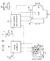
- Fig. 6 there is shown a schematic configuration of the system whereby a second embodiment of the automatic speed change according to the present invention may be carried out.
- the system shown in Fig. 6 differs from that shown in Fig. 4 in that, as is obvious from Fig. 6, it further comprises a running mode changeover switch 70 and its manipulating lever 71 provided in the vehicle running control circuit.
- the arrangement is made such that, when the manipulating lever 71 for changeover of the running mode is switched over to a heavy loading position P and a light loading position E, respectively, a heavy load signal S1 and a light load signal S2 are input to the engine controller 50 and the power transmission controller 60, respectively, and when the heavy load signal S1 is input to the engine controller 50 and the power transmission controller 60, the maximum output of the engine is set at a high level as shown by a curve "A1" in Fig.
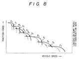
- reference characters d2 to d6 indicate equi-fuel cost curves, respectively.
- the speed change point is changed to a lower speed side and the shift-up point is set at, for exmaple, the number of revolutions N3 (1,800 rpm) of the engine and the shift-down point is set at, for exmaple, the number of revolutions N4 (1,250 rpm) of the engine in Fig. 7.
- FIG. 9 the schematic configuration of a system for carrying out a third embodiment of the automatic speed change method according to the present invention is shown in Fig. 9.
- Fig. 9 is also similar to Fig. 4, the detailed description thereof is omitted.
- the above-mentioned second control circuit 62 is adapted to be input with a signal indicative of the degree of opening of the accelerator transmitted by the accelerator sensor 52, the revolving speed of the input shaft of the transmission transmitted by the input shaft revolving speed detecting sensor 48 and a signal indicative of the present speed stage transmitted by the control circuit 61 so as to compute the deceleration of the vehicle on the basis of the revolving speed of the input shaft of the transmission and transmit as an output a signal indicative of a slope running-up speed corresponding to the deceleration, which has been computed when a speed stage signal is input on the basis of the thus computed deceleration, to a first control circuit 61.
- the second control circuit 62 computes the deceleration of the vehicle when it is supplied or input with any one of signals indicative of the forward seventh to fifth speeds F7 to F5. This computation of the deceleration of the vehicle is made when the signal indicative of the degree of opening of the accelerator in full open state lasts for 0.5 seconds. This is because if the accelerator is not fully open the degree of opening of the accelerator tends to fluctuate due to the vibration of the vehicle body thus rendering the deceleration unstable.
- the deceleration of the vehicle is computed by a formula " KX(Ni-N)/T " wherein K is a correction coefficient, Ni the revolving speed of the input shaft of the transmission which has changed from N after the lapse of T second.
- the tractive force required for the vehicle in running up a slope can be computed on the basis of the speed stage when the vehicle is running on a flatland and the deceleration which occurs when the vehicle has entered a slope, and a slope ascending speed can be decided on the basis of the thus computed, required tractive force.
- the engine will overrun, and therefore the arrangement is made such that when the actual slope running-up speed of the vehicle has been set at a value corresponding to the selected slope running-up speed a speed change signal is transmitted by the first control circuit 61 so as to make a speed change to a preset lower speed stage.
- the deactivating conditions referred above include that the gear shift lever 63 has been changed over, that a braking signal has been input, and that the accelerator has been put in partially open or closed condition.
- the deceleration of the vehicle is computed in the above-mentioned embodiment, it is also possible to detect the acceleration of the vehicle and make an automatic speed change to a slope running-up speed stage according to the thus detected acceleration.
- first and second control circuits 61 and 62 in the transmission controller 60 may be configured as one microcomputer in order to conduct the ordinary automatic speed change and the automatic speed change to be made in running up a slope.
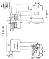
- a fourth embodiment of the automatic speed change method according to the present invention will now be described below with reference to the schematic configuration of the running control system of a dump truck for use as a construction vehicle as shown in Fig. 10.
- Fig. 10 is also similar to Fig. 4, the detailed description thereof is omitted herein.
- the above-mentioned second control circuit 62 is supplied or input with a signal indicative of the degree of opening of the accelerator transmitted by the accelerator sensor 52, a signal indicative of the revolving speed of the input shaft of the transmission or speed change gear transmitted by the input shaft revolving speed detecting sensor 48, and a signal indicative of braking transmitted by a braking sensor 64 and transmits a lower speed stage signal to the first control circuit 61 when it has discriminated that the vehicle is in an idling condition.
- the arrangement is made such that when the vehicle is running in the ordinary speed change mode it is discriminated whether the vehicle speed is at a high speed stage, for example, any one of the forward seventh to fifth speeds F7 to F5, and if it has been discriminated that the vehicle speed is at a high speed stage, then it is discriminated whether the degree of opening of the accelerator is zero. If it has been discriminated that the degree of opening of the accelerator is zero, then it is detected whether a braking signal is input continuously for more than 10 seconds. In case the braking signal is not input in the above-mentioned operation it is proved that the vehicle is in an idle running condition.
- the ordinary automatic speed change mode is prohibited and the present high speed stage is maintained, and the present vehicle speed is computed and detected an the basis of the revolving speed of the input shaft of the speed change gear, whilst when the vehicle speed has reached a preset low speed stage which is, for example, a value corresponding to the forward second speed F2, the second control circuit will transmit a signal indicative of the preset low speed stage as an output signal to the first control circuit 61. Then, the first control circuit 61 will transmit a speed change signal so that the vehicle speed may be automatically changed over to the preset low speed stage.
- a preset low speed stage which is, for example, a value corresponding to the forward second speed F2
- the second control circuit will transmit a signal indicative of the preset low speed stage as an output signal to the first control circuit 61.
- the first control circuit 61 will transmit a speed change signal so that the vehicle speed may be automatically changed over to the preset low speed stage.
- the deactivating conditions referred to above include that the gear shift lever 63 has been switched over, that the braking signal has been input for more than 10 seconds, that the vehicle has been running idly for more than 60 seconds, and that the degree of opening of the accelerator is not zero.
- first and second control circuits 61 and 62 of the power transmission controller 60 may be integrated into one unit so as to conduct the ordinary automatic speed change and also perform the above-mentioned operation shown in Fig. 12 so that the vehicle speed may be changed straight over to a low speed stage when the vehicle is in an idle running condition.
- the power transmission controller 60 when the power transmission controller 60 is input with a speed change command, for example, a signal indicative of a vehicle speed which exceeds a speed change point, the power transmission controller 60 will transmit a deenergizing signal to the solenoid 40a so as to allow the lock-up changeover or control valve 40 to assume its draining position to disengage the lock-up clutch 18.
- a speed change command for example, a signal indicative of a vehicle speed which exceeds a speed change point
- a solenoid deenergizing signal is transmitted to the solenoid 40a which is energized at that time to thereby allow the speed change valve associated therewith to assume its draining position, and also a solenoid energizing signal is transmitted to energize the solenoid for the speed stage to which a speed change is to be made thereby allowing the speed change valve associated therewith to assume its supply position to make the speed change.
- a signal for energizing the solenoid 40a is transmitted so as to allow the lock-up changeover valve 40 to assume its supply position to connect or engage the lock-up clutch 18.
- the second control circuit 54 in the engine controller 50 is input with the number of revolutions of the engine and the position of the rack rod as well as a speed change command transmitted by the power transmission controller 60.
- the speed change command is a shift-down
- the first control circuit 53 of the engine controller 50 will transmit a signal indicative of a speed increase to the control valve 45 for a predetermined period of time, for example, one second immediately before the power transmission controller 60 transmits a signal for energizing the above-mentioned solenoid 40a, thereby increasing the amount of the fluid to be supplied into the chamber 44a of the hydraulic cylinder 44 to move the rack rod 43 so as to increase the amount of the fuel to be injected into the engine thus allowing the engine to be rotated at a higher speed for a predetermined time.
- the number of revolutions of the engine will correspond to the number of revolutions of the input shaft of the power transmission or speed change gear so that the occurrence of any shocks due to a speed change can be avoided.
- the second control circuit 54 may be provided in the transmission controller 60 to conduct a speed change as indicated in the flow chart shown in Fig. 13.
- a signal for energising the solenoid 40a is transmitted as an output signal so as to allow the lock-up clutch to be connected or engaged, whilst when the speed change command is a shift-down, there is no issuance of any speed stage signal when the vehicle is stopped, and when no signal indicative of braking is input, a signal for increasing the rotational speed of the engine is transmitted for a predetermined time. Further, in case any speed stage signal is issued when the vehicle is stopped and in case a signal indicative of braking is input, the vehicle may be stopped in the condition that the engine is connected through a torque converter with the power transmission or speed change gear without transmitting a signal for energizing the solenoid 40a.
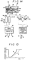
- Fig. 14 shows the schematic configuration of a system for carrying out the automatic speed change method of the sixth embodiment of the present invention.
- the component parts indicated with the same reference numerals as those used in Fig. 4 have the same functions, and therefore the detailed description thereof is omitted herein.
- the method according to the sixth embodiment can be achieved by controlling the above-mentioned modulation valve (inching valve) 38.
- the modulation valve (inching valve) 38 is of a publicly known construction in that it comprises a pressure regulating valve 57 and a back pressure valve 58 fitted in a valve hole 56 formed in its valve body 55, the pressure regulating valve 57 containing a load piston 59 therein so as to introduce the pressure in a constricted portion 64 having a smaller diameter therein to urge the pressure regulating valve 57 to the right hand to allow communication between an inlet port 65 and a draining port 66, and the back pressure valve 58 having a spring 67 for urging the pressure regulating valve 57 through the back pressure valve 45 to the left so as to cut off the communication between the inlet port 65 and the draining port 66, the arrangement is made such that the fluid under pressure in an outlet port 68 is supplied into a spring chamber 69 so as to repeat the rightward movement of the pressure regulating valve 57 by the load piston 59 and the leftward movement of the pressure regulating valve 57 by the resilient force of the spring 67 and also by the action of
- the above-mentioned spring chamber 69 is connected to the drain through a first restriction 72, a second restriction 73, a first solenoid valve 74 and a second solenoid valve 75.
- the first and second solenoid valves 74 and 75 are normally held at their cut-off positions I, but are arranged to be changed over to their communicating positions II when the first and second solenoids 74a and 75a associated therewith, respectively, are energized.
- Reference numeral 76 denotes a controller for the progressive pressure increasing valve adapted to discriminate whether the vehicle is in unloaded or loaded condition on the basis of the suspension pressure transmitted by a suspension pressure sensor 3a provided in the aforementioned suspension cylinder 3 and transmit a signal for energizing the first solenoid 74a when the vehicle is in an unloaded condition and transmit a signal for energizing the second solenoid 75a when the vehicle is in a loaded condition so that when the vehicle is in an unloaded condition part of the fluid under pressure in the outlet port 68 is allowed to flow through the first restriction 72 and then through the first solenoid valve 74 into the drain to thereby reduce the fluid pressure force on the side of the outlet port to be supplied into the spring chamber 69, whilst when the vehicle is in a loaded condition part of the fluid under pressure in the outlet port 68 is allowed to flow through the second restriction 73 and then through the second solenoid valve 75' into the drain thereby reducing the fluid pressure force on the side of outlet port.
- the time required for increasing the fluid pressure to a predetermined valve will increase so that a speed change can be made without causing any shocks due to a speed change even if the torque transmitted by the power transmission 16 is small, whilst when the vehicle is in a loaded condition; that is, it is in a heavy load condition that the power transmission torque is high, the time required for increasing the fluid pressure to a predetermined value is reduced so that even if the torque transmitted by the power transmission 16 is high the time required until a condition is reached wherein the clutch plates are forced to engage completely with each other to ensure power transmission can be reduced whereby rendering it possible to make a speed change in a short time.
Abstract
Description
- This invention relates to a method for automatically changing the speed of a dump truck for use as a construction vehicle to a speed stage to be determined according to the operating condition of a power transmission or speed change gear thereof when the vehicle is running, and also relates to a method for operating the power transmission thereof.
- As for the method of automatically changing the running speed of a vehicle wherein the output side of the engine is connected to a torque converter provided with a lock-up clutch, the output side of the torque converter is connected to the input side of a hydraulically actuated power transmission or speed change gear having a plurality of speed stage clutches, and the output side of the power transmission is connected through a differential gear mechanism to the left and right drive wheels, an automatic speed change method has been known wherein speed increasing points and speed decreasing points, i.e., speed change points are set on the basis of the relationship between the tractive force at each of speed stages of the power transmission when the engine is developing a maximum speed and the vehicle speed at that time, and the vehicle speed is detected from the number of revolutions of the engine etc., and when the thus detected vehicle speed exceeds a speed change point an automatic speed changeover to a next speed stage can be made.
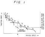
- For example, as shown in Fig. 1, the arrangement is made such that speed change points f₁ to f₆ are set from the relationship between the tractive forces when the engine is developing a maximum output or power at forward first to seventh speeds F₁ to F₇ and running speeds of the vehicle, and when the vehicle speed exceeds each of the speed stages it is automatically changed over to a next speed stage.
- That is to say, the maximum outputs or powers of the engines mounted on dump trucks for use as construction vehicles are not so high as those outputs required for them, and the weight of such vehicles in a loaded condition varies so much from that in an unloaded condition. Further, because the loadage and the gradient of roads on which vehicles run vary so much, the loading imposed on dump trucks for use as construction vehicles fluctuates largely, and also since it is difficult to detect the cargo on board and the gradient of roads with a high accuracy, it has been a common practice for dump trucks for use as construction vehicles to set speed change points which correspond always to the maximum output condition developed by the engine mounted on each of them, assuming cases where the loading imposed on them is high, and to run them with their engines developing maximum outputs.
- In GB-A-2 069 075, a control system for shiftable multi-speed hydraulically-operated power transmission and an electronic controller therein is disclosed. This control system discloses the features of the preamble parts of the independent claims. The control system is used in off-highway trucks as, for example, dump truck type vehicles. The output side of an engine is connected to a torque converter that is provided with a lock-up clutch. The output side of the torque converter is connected to the input side of a hydraulically-actuated power transmission having several hydraulically-operating shifting clutches therein. The output side of the power transmission is connected through a differential gear mechanism to wheels. Further, the speed stages are selected under control of a built-in controller that receives electric signal information from a range selector switch, a detector means, a limit switch, and a rotary switch.
- The electronic controller receives the relevant signal information and provides control signals to effect automatic shifting, provided predetermined operating conditions are met. The speed signals, or shift points for upshift, are adjustable or pre-settable for defining each speed range. The downshift points are also adjustable. Shifting takes places automatically upon achievement of transmission output speeds as scuttled for each range and indicated by a sensor. However, the highest speed range is selected by the operator and limits the transmission gear range regardless of higher transmission output speeds. If the operator moves the shift selector to a lower gear, the controller effects a lower gear downshift only when the correct speed is achieved by the torque converter turbine shaft, sensed by a respective sensor. Moreover, the lock-up clutch is engaged and disengaged at pre-chosen speeds and is to be disengaged every time the transmission shifts. Thereafter, it must be re-engaged.
- In the above-mentioned conventional automatic speed change method, in case the loading on a vehicle is extremely light as, for example, in the case of an unloaded vehicle running on a flatland or in case a loading on the vehicle is comparatively light as in the case of the vehicle in a light load condition running up a slope, the output developed by the engine is not utilized fully thus consuming an extra fuel ineffectively. This is because the output required for a dump truck for use as a construction vehicle in the above-mentioned light load condition is in fact less than the maximum output developed by the engine. Further, in mining stopes etc., a plurality of dump trucks for use as construction vehicles having different engine outputs usually run along the same course, and so it is not allowed for only one truck to run at a higher speed than the others at a maximum output developed by its engine, and the truck must be driven at a lower speed which is adjusted to the lower speeds of other vehicles. Therefore, vehicles with higher engine outputs are required to run at a lower speed stage; that is, a higher number of revolutions of the engine thereof, resulting in increases in the full consumption rate.
- Whilst, as to the engine output, there are cases where even when a vehicle is driven at a speed stage higher than the current running speed the same tractive force can be obtained. In Fig. 1, if a vehicle subjected to a load, for example, at point "a" is running at a speed of V₁, then the vehicle speed is set at the forward fifth speed F₅, whilst from the viewpoint of the tractive force (engine output) it becomes possible for the vehicle to run at the speed stage for the forward sixth speed F₆.
- Whilst, in case a dump truck for use as a construction vehicle which is running on a flatland at a high speed stage runs up a slope, for example, or in case the running condition of the vehicle is changed over to idling condition by reducing the degree of opening of the accelerator to zero, it is required for the vehicle to make plural times of speed changes in turn from high speed stages to low speed changes in a short time. If such speed changes are made plural times in a short time, then excessive forces tend to be exerted on the power transmission system from the transmission or speed change gear to the drive wheels thus impairing the durability of the power transmission system and causing shocks each time a speed change is made and also causing plural times of changes in the vehicle speed thereby giving the driven rough ride.
- Further, as for the conventional speed change operation for the above-mentioned dump trucks for use as construction vehicles, there has been known a speed change operational method wherein a speed change is made in a condition that the lock-up clutch is disconnected and the output side of the engine is connected through a torque converter to the input side of the power transmission or speed change gear and, after the completion of the speed change, the lock-up clutch is connected again so that the output side of the engine may be connected directly to the input side of the power transmission.
- In such a speed change operational method, when the vehicle is in a normal running condition, the engine output can be directly transmitted to the power transmission not through the intermediary of the torque converter thus reducing the power losses, and each time a speed change is made, the engine output is input or transmitted through the torque converter to the power transmission so that even if the revolving speed of the input shaft of the power transmission does not correspond to that of the output shaft the shocks due to speed changes can be absorbed by the torque converter to some degree thereby reducing the magnitude of such shocks.
- However, if after the completion of a speed change and when connecting or engaging the lock-up clutch the number of revolutions of the engine does not correspond to that of the input shaft of the speed change gear, then a shock due to a speed change will occur.
- When, for example, a speed change to a speed stage lower than the present speed stage, i.e., a shift-down operation is made, the load imposed on the engine will increase, thus causing a reduction in the number of revolutions of the engine so that when the lock-up clutch is connected the number of revolutions of the engine becomes lower than that of the input shaft of the power transmission or speed change gear thereby causing a shock due to the speed change.
- Further, as for the conventional speed change operation, there has been known a speed change operational method wherein the supply of the pressurized fluid discharged by a pressurized fluid source to each of a plurality of speed stage clutches is controlled by each of the speed change valves associated therewith, and a progressive pressure increasing valve for gradually raising the fluid pressure in the pressurized fluid supply source is provided so that when supplying the fluid under pressure to a predetermined speed stage clutch the fluid pressure can be increased progressively to ensure smooth connection or engagement of the speed stage clutch without causing any shocks due to a speed change.
- Each of the speed stage clutches comprise a plurality of clutch plates which are rendered operative when they are urged into contact with one another and which are rendered inoperative when they are separated from one another. If the time required until the fluid pressure is increased to a predetermined value becomes longer, then each of the speed stage clutches can be engaged more smoothly. However, on the other hand, a longer time is required to make a speed change. Whilst, if the fluid pressure is increased to a predetermined value in a short time, then the time required for the speed change can be reduced, but on the other hand the speed stage clutch is engaged quickly thus causing a big shock due to the speed change. For this reason, the time required for increasing the fluid pressure to a predetermined value is usually set at one intermediate value of the two; that is to say, progressive pressure increasing characteristics are set by means of a progressive pressure increasing value.
- Whilst, the loading imposed on the dump trucks for use as construction vehicles varies remarkably between loaded and unloaded conditions, and so they are driven repeatedly in heavy and light load conditions. When the vehicle is running in a heavy load condition, a high load is applied to the power transmission so that the torque transmitted thereby becomes high,whilst when running in a light load condition, a low load is applied to the transmission so that the torque transmitted thereby becomes low.
- If the torque transmitted to the power transmission is high, the clutch plates tend to slip, while, if the torque is low the tendency of causing slip of the clutch plates is reduced. Therefore, if as mentioned above, the time required for increasing the fluid pressure to a predetermined value is constant and if the torque transmitted to the power transmission is high, the time required until the clutch plates are engaged completely without causing any slip to ensure satisfactory power transmission tends to increase thus increasing the time required for making a speed change. Whilst, in case the torque transmitted to the power transmission is low, it becomes possible to attain a condition that satisfactory power transmission can be made in a short time thereby increasing the tendency of occurrence of big shocks due to a speed change.
- The present invention has been contemplated in view of the above-mentioned circumstances, and has for its first object to provide a method for automatically changing the speed of a dump truck for use as a construction vehicle wherein the engine output can be utilized effectively and efficiently thereby reducing the fuel consumption.
- This object is solved by the characterizing features of independent claims 1 or 3. Advantageous embodiments of the invention are disclosed by the subclaims.
- The above and many other advantages, features and additional objects of the present invention will become apparent to those versed in the art upon making reference to the following detailed description and accompanying drawings in which preferred structural embodiments incorporating the principles of the present invention are shown by way of illustrative example only.
-
- Fig. 1 is an explanatory view of an example of speed change pattern for automatic speed change of a dump truck for use as a construction vehicle;
- Fig. 2 is a schematic, developed explanatory view of a power transmission system of a dump truck for use as a construction vehicle;
- Fig. 3 is a view showing a hydraulic circuit for effecting speed changes which is used in the power transmission system shown in Fig. 2;
- Fig. 4 is a schematic, overall explanatory view of a system for carrying out one embodiment of the automatic speed change method according to the present invention;
- Fig. 5 is a diagram showing an example of the engine output characteristics developed by the dump truck for use as a construction vehicle;
- Fig. 6 is a schematic, overall explanatory view of a system for carrying out another embodiment of the automatic speed change method according to the present invention;
- Fig. 7 is a diagram showing, in combination, the engine output characteristic curves and equi-fuel cost curves obtained by the automatic speed change method which is carried out in the system as shown in Fig. 6;
- Fig. 8 is an explanatory view of the speed change pattern achieved by the automatic speed change method which is carried out in the system as shown in Fig. 6;
- Figs. 9 and 10 are schematic, overall explanatory views of the systems for carrying out further two embodiments of the automatic speed change method according to the present invention;
- Fig. 11 is an operational flow chart of the automatic speed change method which is carried out in the system as shown in Fig. 9;
- Fig. 12 is an operational flow chart of the automatic speed change method which is carried out in the system as shown in Fig. 10;
- Fig. 13 is an operational flow chart of another embodiment of the automatic speed change method according to the present invention;
- Fig. 14 is a schematic explanatory view the construction of the system for carrying out a further embodiment of the automatic speed change method of the present invention; and
- Fig. 15 is a diagram showing the pressure characteristics obtained by a progressive pressure increasing value used in the system as shown in Fig. 14.
- The method for automatically changing the speed of a dump truck for use as a construction vehicle according to the present invention will now be described in detail below with reference to the accompanying drawings.
- A dump truck for use as a construction vehicle has a vessel for loading earth and sand or rocks etc., which is mounted on the vehicle body thereof so as to be tilted freely, and left and right steering wheels and left and right drive wheels mounted through suspension cylinders on the vehicle body.
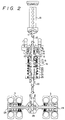
- In the power transmission system of a dump truck for use as a construction vehicle as shown in Fig. 2, the above-mentioned drive wheels are denoted by
reference numerals wheels engine 10. - Stating in brief, in Fig. 2, the
engine 10 has anoutput shaft 11 which is connected through adrive shaft 12 to apump 14 for use with atorque converter 13, and a turbine 15 of thepump 14 is connected to aninput shaft 17 of a power transmission orspeed change gear 16. Further, there is provided a lock-upclutch 18 for connecting the turbine 15 of thepump 14. Thepower transmission 16 connects theinput shaft 17 through a plurality ofplanetary gear mechanisms 19 to anoutput shaft 20 and is adapted to turn on and off ahigh speed clutch 21, alow speed clutch 22, first tofourth speed clutches 23 to 26, and a reversingclutch 27 so that a speed change to either one of the forward first to seventh speeds and a reversing speed, respectively. - The
output speed 20 of the power transmission orspeed change gear 16 is connected through adifferential gear 28 and final reduction gears 29 to thedrive wheels - As shown in Fig. 3, the above-mentioned
clutches 21 to 27 are controlled, respectively, so as to be turned on and off by controlling the supply of fluid under pressure through the first to seventhspeed change valves 31 to 37, respectively. The first to seventhspeed change valves 31 to 37 are adapted to be changed over to their fluid supply positions when theirsolenoids 31a to 37a are energized and to assume their fluid supply cut-off positions when the solenoids are deenergized. The input side of the first and secondspeed change valves speed change valves 33 to 37 is provided with another modulation valve (inching valve) 38 so that the pressure of the fluid under pressure supplied into each of theclutches 21 to 27 may be raised smoothly. The above-mentioned lock-up clutch 18 is supplied with the fluid under pressure discharged by apump 39 through a lock-up changeover orcontrol valve 40. The lock-upchangeover valve 40 is adapted to be changed over to a fluid supply position when itssolenoid 40a is energized so as to render the lock-up clutch 18 on or operative thus connecting thepump 14 and the turbine 15, and to assume a fluid supply cut-off position when thesolenoid 40a is deenergized thereby rendering the lock-up clutch 18 off or inoperative. - Fig. 4 is a schematic, overall explanatory view of a system for carrying out one embodiment of the automatic speed change method according to the present invention.
- In Fig. 4, the
engine 10 is provided with afuel injection pump 42a whose amount of fuel injection is controlled by anelectronic control governor 42. Theelectronic control governor 42 is adapted to control the amount of fuel to be injected into the engine by reciprocating arack rod 43 by the action of ahydraulic cylinder 44. Thehydraulic cylinder 44 has a chamber 44a which is supplied through acontrol valve 45 with the fluid under pressure discharged by a pressurized fluid supply source, not shown, and there is provided a rackposition detecting sensor 46 which comprises a differential transformer. Further, there is provided an enginerevolution detecting sensor 47 adapted to detect the number of revolutions of theoutput shaft 11 of theengine 10. And, thepower transmission 16 is provided with an input shaft revolvingspeed detecting sensor 48 and an output shaft revolvingspeed detecting sensor 49 which are adapted to detect the revolving speeds of theinput shaft 17 and theoutput shaft 20, respectively. -
Reference numeral 50 denotes an engine controller which comprises afirst control circuit 53 and asecond control circuit 54 for conducting operational controls in such a manner that when it is supplied or input with a signal indicative of the degree of opening of the accelerator transmitted by anaccelerator sensor 52 adapted to detect the amount of depression of an accelerator pedal 51 (the degree of opening of the accelerator), it may transmit a control signal as an output signal to thecontrol valve 45 so as to control the supply of the fluid under pressure discharged by the pressurized fluid supply source into the chamber 44a of thehydraulic cylinder 44 to thereby reciprocate therack rod 43 so that the position of the rack detected by the rackposition detecting sensor 46 may become a rack position corresponding to the signal indicative of the degree of opening of the accelerator. Thesecond control circuit 54 is adapted to compute the engine output condition and the engine torque according to the number of revolutions of the engine transmitted by the enginerevolution detecting sensor 47 and the position of the rack transmitted by the rackposition detecting sensor 46. - Stating in brief, the engine output characteristic curves (A, B₁, B₂, B₃ ... in Fig. 5) or the engine output condition can be seen from the position of the rack, whilst the positions on the engine output torque curves (each of Points P₁, P₂, P₃ ... in Fig. 5) or the torque can be seen from the number of revolutions of the engine.
-
Reference numeral 60 denotes a controller for the power transmission or speed change gear which comprises afirst control circuit 61 and asecond control circuit 62 for conducting operational controls in such a manner that it may compute the vehicle speed on the basis of either the input shaft revolving speed from the input shaft revolvingspeed detecting sensor 48 provided in thepower transmission 16 or the output shaft revolving speed from the output shaft revolvingspeed detecting sensor 49 and, when the vehicle speed is more than a preset speed change point, it may transit or output a control signal to the above-mentioned first to seventhspeed change valves 31 to 37 and the lock-up change-over orcontrol valve 40 so as to disconnect the lock-upchangeover valve 18 and connect theengine 10 with thepower transmission 16 through thetorque converter 13 and then change the present speed stage over to a higher speed stage or a lower speed stage and- after the completion of the speed change, connect the lock-up clutch 18 again to thereby directly connect theengine 10 with thepower transmission 16. - Further, the
first control circuit 61 is supplied or input with gear shift position signals R, N, D, V, IV, III and II from thegear shift lever 63 so that when the signal R is input a speed change to the reversing speed is made; when the signal N is input a speed change to the neutral is made; and when any one of the signals D, V, IV, III and II is input an automatic speed change between the predetermined speed stages is made. - The above-mentioned
second control circuit 62 is adapted to discriminate if it is possible to make a speed change from the present speed stage to a higher speed on the basis of the engine output condition and the torque transmitted by thecontrol circuit 54 in theengine controller 50 and a speed stage signal transmitted by thefirst control circuit 61, and when it is proved that the present speed stage can be changed to a higher speed, transmit an output signal to the first to seventhspeed change valves 31 to 37 and the lock-upchangeover valve 40 so as to make a speed change to a higher speed stage and, at the same time, transmit a fuel injection control signal for controlling the engine at an equi-horse power as an output signal to thefirst control circuit 53 in theengine controller 50. - Stating in brief, the
second control circuit 62 serves as a microcomputer which is adapted to compute the engine output or horsepower on the basis of the engine output condition and the torque which are input to it (For example, the partial output condition curve "B" and the point "P₁" along the curve) and also compute the number of revolutions N₁ of the engine from the point of intersection (X in Fig. 5) of an equi-horsepower curve (curve "e" in Fig. 5) with an engine characteristic curve in a condition that the engine is developing its maximum output (curve "A" in Fig. 5) and, when the product of the number of revolutions N₁ of the engine and the speed reduction ratio at a higher speed stage when a speed change to the high speed stage is made is larger than the product of the thus input number of revolutions N₂ of the engine and the speed reduction ratio at the present speed stage, discriminate that a speed change to a higher speed stage can be made and generate a shift-up signal as an output signal. - Moreover, the
second control circuit 62 will compute, in fact, a slightly lower number of revolutions of engine in order to provide an allowance to the thus actually computed number of revolutions of the engine. - Stating more concretely, when the
engine 10 is in a partial output developing condition with theaccelerator 51 kept in a semi-opened state, which is shown , for example, by a curve "B₁" in Fig. 5, and the load on a dump truck for use as a construction vehicle is small as shown by "a" in Fig. 1; that is, the vehicle is in an unloaded condition, and if the vehicle is driven at a constant speed which is, for example, a speed V₁ shown in Fig. 1, then the vehicle speed is automatically changed over to a speed stage corresponding to the vehicle speed V₁ such as, for example, the forward fifth speed F₅, by the action of thefirst control circuit 61 in thepower transmission controller 60 in the same manner as that of the conventional system. - As a result, the
second control circuit 62 is supplied or input with a signal indicative of the forward fifth speed F₅ as well as the engine output condition and the engine torque available at that time so as to compute the engine horsepower, and discriminate the present position Y from the engine horsepower (load) and the vehicle speed as shown in Fig. 1, and also discriminate that the vehicle is running at a fixed, constant speed from the fact that the signal indicative of the degree of opening of the accelerator remains unchanged and compute the number of revolutions N₁ of the engine at a point of intersection "X" of the equi-horsepower curve "e" passing a point P₁ in Fig. 5 and the characteristic curve "A" of the engine when it is developing its maximum output. - Then, this number of revolutions N₁ of the engine is multiplied by the speed reduction ratio at the forward sixth speed F₆, and when the product obtained thereby is larger than the product of the speed reduction ratio at the forward fifth speed F₅ to which an automatic speed change is made and the number of revolutions N₂ of the engine obtained at that time, the
second control circuit 62 will transmit a shift-up signal as an output signal to thefirst control circuit 61 so as to make an automatic speed change to the forward sixth speed F₆ in the same manner as that of the ordinary automatic speed change operation. - Simultaneously with the above-mentioned automatic speed change operation, the
second control circuit 62 will transmit a signal indicative of "the engine should be controlled at an equi-horse power" to thefirst control circuit 53 in theengine controller 50 so as to control the amount of the fuel to be injected into the engine. - In case a sufficient engine output is available as mentioned above, the vehicle can be driven at a constant speed after an automatic speed change to a speed stage higher than that selected by the ordinary automatic speed change has been made so that the number of revolution of the engine can be decreased so as to reduce the fuel consumption rate and the horsepower loss thereby achieving a significant saving in the fuel consumption.
- Whilst, in the above-mentioned embodiment, the control of the engine output condition and the engine torque is made by means of the
second control circuit 54 in theengine controller 50, it may be made by means ofsecond control circuit 62 in thepower transmission controller 60. Thefirst control circuit 61 and thesecond control circuit 62 may be used as one microcomputer unit in order to make the ordinary automatic speed change, and a shift-up operation when the vehicle is running at a constant speed. - Further, although in the above-mentioned embodiment the arrangement is made such that a shift-up signal is transmitted according to the relationship between the number of revolutions of the engine and the speed reduction ratio, it is also possible to transmit a shift-up signal as an output signal according to the relationship between the engine torque and the speed reduction ratio.
- Stating in brief, the arrangement is made such that in case of
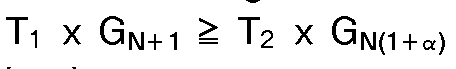
- In the above formula, reference character T₁ denotes the torque at the number of revolutions N₁ of the engine, T₂ the torque at the number of revolutions N₂ of the engine, GN the speed reduction ratio at each of speed stages, and α an allowance factor for torque.
- Further, it may be effected to predetermine the zone where a shift-up is to be made on the basis of the engine output characteristic curve by computing it previously and to conduct a shift-up operation in case the vehicle speed is within such a range. By so doing, the need for conducting the above-mentioned complicated computation can be eliminated.
- In Fig. 6 there is shown a schematic configuration of the system whereby a second embodiment of the automatic speed change according to the present invention may be carried out.
- In Fig. 6, component parts indicated by the same reference numerals and characters used in the configuration shown in Fig. 4 have the same functions, and so the detailed description thereof is omitted herein to avoid duplication in explanation.
- The system shown in Fig. 6 differs from that shown in Fig. 4 in that, as is obvious from Fig. 6, it further comprises a running mode changeover switch 70 and its manipulating
lever 71 provided in the vehicle running control circuit. The arrangement is made such that, when the manipulatinglever 71 for changeover of the running mode is switched over to a heavy loading position P and a light loading position E, respectively, a heavy load signal S₁ and a light load signal S₂ are input to theengine controller 50 and thepower transmission controller 60, respectively, and when the heavy load signal S₁ is input to theengine controller 50 and thepower transmission controller 60, the maximum output of the engine is set at a high level as shown by a curve "A₁" in Fig. 7 and a shift-up point (the number of revolutions N₁ of the engine = 2,230 rpm) and a shift-down point (the number of revolutions N₂ of the engine = 1,400 rpm) are set so that a heavy load running mode suitable for running the vehicle at a heavy load can be obtained. - Further, when the light load signal S₂ is input to the
engine controller 50, the stroke of therack rod 43 corresponding to a signal indicative of the degree of opening of the accelerator to set the maximum output of the engine at a lower level as shown by a curve "A" in Fig. 7, and the rated output of the engine is set at a level as shown by "C" which is inside a high equi-full cost curve d₁ so that the number of revolutions of the engine can be set at, for example, 1,700 rpm. Further, reference characters d₂ to d₆ indicate equi-fuel cost curves, respectively. - Still further, when the light load signal S₂ is input to the
power transmission controller 60, the speed change point is changed to a lower speed side and the shift-up point is set at, for exmaple, the number of revolutions N₃ (1,800 rpm) of the engine and the shift-down point is set at, for exmaple, the number of revolutions N₄ (1,250 rpm) of the engine in Fig. 7. - As a result, a light load running mode suitable for running the vehicle at a light load can be obtained.
- As is apparent from the foregoing description, when the
lever 71 for the running mode changeover switch 70 is set at a light loading position E the maximum output of the engine is reduced, and also the speed change point of the transmission or speed change gear is changed over to a lower speed stage (the tractive force and the speed change point will change as shown, for example by dotted lines in Fig. 8) so that in addition to the shift-up of the power transmission, a further improvement in the fuel cost for the engine can be achieved. - Next, the schematic configuration of a system for carrying out a third embodiment of the automatic speed change method according to the present invention is shown in Fig. 9.
- Since Fig. 9 is also similar to Fig. 4, the detailed description thereof is omitted.
- In Fig. 9, the above-mentioned
second control circuit 62 is adapted to be input with a signal indicative of the degree of opening of the accelerator transmitted by theaccelerator sensor 52, the revolving speed of the input shaft of the transmission transmitted by the input shaft revolvingspeed detecting sensor 48 and a signal indicative of the present speed stage transmitted by thecontrol circuit 61 so as to compute the deceleration of the vehicle on the basis of the revolving speed of the input shaft of the transmission and transmit as an output a signal indicative of a slope running-up speed corresponding to the deceleration, which has been computed when a speed stage signal is input on the basis of the thus computed deceleration, to afirst control circuit 61. - Stating more concretely, the
second control circuit 62 computes the deceleration of the vehicle when it is supplied or input with any one of signals indicative of the forward seventh to fifth speeds F₇ to F₅. This computation of the deceleration of the vehicle is made when the signal indicative of the degree of opening of the accelerator in full open state lasts for 0.5 seconds. This is because if the accelerator is not fully open the degree of opening of the accelerator tends to fluctuate due to the vibration of the vehicle body thus rendering the deceleration unstable. - Further, the deceleration of the vehicle is computed by a formula "

- In case the thus computed deceleration is compared with the present value of deceleration and it is formed that the former is more than the latter, it is discriminated that the vehicle has entered a slope with a high gradient, and a predetermined slope running-up speed is selected on the basis of the present speed stage and the deceleration which occurs when running up a slope. The arrangement is made such that when the actual vehicle speed has been become a value corresponding to the slope running-up speed stage a speed change signal is transmitted or output by the
first control circuit 61 so that an automatic speed change to a preset lower speed stage can be made. - That is to say, the tractive force required for the vehicle in running up a slope can be computed on the basis of the speed stage when the vehicle is running on a flatland and the deceleration which occurs when the vehicle has entered a slope, and a slope ascending speed can be decided on the basis of the thus computed, required tractive force.
- Thus, it is possible to predetermine the slope running-up speed on the basis of the speed reduction ratio at each of the speed stages and the output of the engine, and predetermine the slope running-up speed on the basis of such actual measurement data. An optimum slope running up speed change can be selected by the preset value, the speed stage when the vehicle is actually on the flatland, and the deceleration which occurs when the vehicle is running up on the slope.
- Further, if the vehicle speed is changed over to a slope running-up speed stage which is selected when the actual slope running-up speed is higher than a value corresponding to the selected slope running-up speed, then the engine will overrun, and therefore the arrangement is made such that when the actual slope running-up speed of the vehicle has been set at a value corresponding to the selected slope running-up speed a speed change signal is transmitted by the
first control circuit 61 so as to make a speed change to a preset lower speed stage. - And, when the
first control circuit 61 is input with deactivating conditions the speed change mode is returned by thefirst control circuit 61 to the ordinary automatic speed change mode. - The deactivating conditions referred above include that the
gear shift lever 63 has been changed over, that a braking signal has been input, and that the accelerator has been put in partially open or closed condition. - If the above operation is shown by a flow chart, the result as shown in Fig. 11 is obtained.
- Further, while the deceleration of the vehicle is computed in the above-mentioned embodiment, it is also possible to detect the acceleration of the vehicle and make an automatic speed change to a slope running-up speed stage according to the thus detected acceleration.
- Stating in brief, it may be made to detect the rate of change in the vehicle speed and automatically change the vehicle speed over to a slope running-up speed stage on the basis of the thus detected rate of change in the vehicle speed.
- Further, the first and
second control circuits transmission controller 60 may be configured as one microcomputer in order to conduct the ordinary automatic speed change and the automatic speed change to be made in running up a slope. - A fourth embodiment of the automatic speed change method according to the present invention will now be described below with reference to the schematic configuration of the running control system of a dump truck for use as a construction vehicle as shown in Fig. 10.
- Since Fig. 10 is also similar to Fig. 4, the detailed description thereof is omitted herein.
- In Fig. 10, the above-mentioned
second control circuit 62 is supplied or input with a signal indicative of the degree of opening of the accelerator transmitted by theaccelerator sensor 52, a signal indicative of the revolving speed of the input shaft of the transmission or speed change gear transmitted by the input shaft revolvingspeed detecting sensor 48, and a signal indicative of braking transmitted by abraking sensor 64 and transmits a lower speed stage signal to thefirst control circuit 61 when it has discriminated that the vehicle is in an idling condition. - In the next place, the operation thereof will be described in more concrete manner with reference to the flow chart shown in Fig. 12.
- The arrangement is made such that when the vehicle is running in the ordinary speed change mode it is discriminated whether the vehicle speed is at a high speed stage, for example, any one of the forward seventh to fifth speeds F₇ to F₅, and if it has been discriminated that the vehicle speed is at a high speed stage, then it is discriminated whether the degree of opening of the accelerator is zero. If it has been discriminated that the degree of opening of the accelerator is zero, then it is detected whether a braking signal is input continuously for more than 10 seconds. In case the braking signal is not input in the above-mentioned operation it is proved that the vehicle is in an idle running condition.
- As a result, the ordinary automatic speed change mode is prohibited and the present high speed stage is maintained, and the present vehicle speed is computed and detected an the basis of the revolving speed of the input shaft of the speed change gear, whilst when the vehicle speed has reached a preset low speed stage which is, for example, a value corresponding to the forward second speed F₂, the second control circuit will transmit a signal indicative of the preset low speed stage as an output signal to the
first control circuit 61. Then, thefirst control circuit 61 will transmit a speed change signal so that the vehicle speed may be automatically changed over to the preset low speed stage. - And, when any one of deactivating conditions or requirements are met, the vehicle speed will be returned to the ordinary automatic speed change mode.
- The deactivating conditions referred to above include that the
gear shift lever 63 has been switched over, that the braking signal has been input for more than 10 seconds, that the vehicle has been running idly for more than 60 seconds, and that the degree of opening of the accelerator is not zero. - Further, the first and
second control circuits power transmission controller 60 may be integrated into one unit so as to conduct the ordinary automatic speed change and also perform the above-mentioned operation shown in Fig. 12 so that the vehicle speed may be changed straight over to a low speed stage when the vehicle is in an idle running condition. - Further, the fifth embodiment of the automatic speed change method according to the present invention will be described below with reference to the operational flow chart shown in Fig. 13.
- That is to say; when the
power transmission controller 60 is input with a speed change command, for example, a signal indicative of a vehicle speed which exceeds a speed change point, thepower transmission controller 60 will transmit a deenergizing signal to thesolenoid 40a so as to allow the lock-up changeover orcontrol valve 40 to assume its draining position to disengage the lock-upclutch 18. When this lock-up clutch 18 has been disengaged, a solenoid deenergizing signal is transmitted to thesolenoid 40a which is energized at that time to thereby allow the speed change valve associated therewith to assume its draining position, and also a solenoid energizing signal is transmitted to energize the solenoid for the speed stage to which a speed change is to be made thereby allowing the speed change valve associated therewith to assume its supply position to make the speed change. And, upon the completion of the speed change, a signal for energizing thesolenoid 40a is transmitted so as to allow the lock-upchangeover valve 40 to assume its supply position to connect or engage the lock-upclutch 18. - Whilst, the
second control circuit 54 in theengine controller 50 is input with the number of revolutions of the engine and the position of the rack rod as well as a speed change command transmitted by thepower transmission controller 60. In case the speed change command is a shift-down, after the completion of the shift-down, thefirst control circuit 53 of theengine controller 50 will transmit a signal indicative of a speed increase to thecontrol valve 45 for a predetermined period of time, for example, one second immediately before thepower transmission controller 60 transmits a signal for energizing the above-mentionedsolenoid 40a, thereby increasing the amount of the fluid to be supplied into the chamber 44a of thehydraulic cylinder 44 to move therack rod 43 so as to increase the amount of the fuel to be injected into the engine thus allowing the engine to be rotated at a higher speed for a predetermined time. - As a result, when the lock-up clutch 18 is connected or engaged, the number of revolutions of the engine will correspond to the number of revolutions of the input shaft of the power transmission or speed change gear so that the occurrence of any shocks due to a speed change can be avoided.
- Further, the
second control circuit 54 may be provided in thetransmission controller 60 to conduct a speed change as indicated in the flow chart shown in Fig. 13. - Stating in brief, when the speed change command is not a shift-down, a signal for energising the
solenoid 40a is transmitted as an output signal so as to allow the lock-up clutch to be connected or engaged, whilst when the speed change command is a shift-down, there is no issuance of any speed stage signal when the vehicle is stopped, and when no signal indicative of braking is input, a signal for increasing the rotational speed of the engine is transmitted for a predetermined time. Further, in case any speed stage signal is issued when the vehicle is stopped and in case a signal indicative of braking is input, the vehicle may be stopped in the condition that the engine is connected through a torque converter with the power transmission or speed change gear without transmitting a signal for energizing thesolenoid 40a. - Still further, the sixth embodiment of the automatic speed change method according to the present invention will be described below with reference to Figs. 14 and 15.
- Fig. 14 shows the schematic configuration of a system for carrying out the automatic speed change method of the sixth embodiment of the present invention. The component parts indicated with the same reference numerals as those used in Fig. 4 have the same functions, and therefore the detailed description thereof is omitted herein.
- The method according to the sixth embodiment can be achieved by controlling the above-mentioned modulation valve (inching valve) 38.
- As shown in Fig. 14, the modulation valve (inching valve) 38 is of a publicly known construction in that it comprises a
pressure regulating valve 57 and aback pressure valve 58 fitted in avalve hole 56 formed in itsvalve body 55, thepressure regulating valve 57 containing a load piston 59 therein so as to introduce the pressure in aconstricted portion 64 having a smaller diameter therein to urge thepressure regulating valve 57 to the right hand to allow communication between aninlet port 65 and a draining port 66, and theback pressure valve 58 having aspring 67 for urging thepressure regulating valve 57 through theback pressure valve 45 to the left so as to cut off the communication between theinlet port 65 and the draining port 66, the arrangement is made such that the fluid under pressure in anoutlet port 68 is supplied into aspring chamber 69 so as to repeat the rightward movement of thepressure regulating valve 57 by the load piston 59 and the leftward movement of thepressure regulating valve 57 by the resilient force of thespring 67 and also by the action of the fluid pressure force on the side of the outlet port thereby raising the fluid pressure force in theoutlet port 68 progressively. The above-mentionedspring chamber 69 is connected to the drain through afirst restriction 72, asecond restriction 73, afirst solenoid valve 74 and asecond solenoid valve 75. The first andsecond solenoid valves -
Reference numeral 76 denotes a controller for the progressive pressure increasing valve adapted to discriminate whether the vehicle is in unloaded or loaded condition on the basis of the suspension pressure transmitted by a suspension pressure sensor 3a provided in the aforementioned suspension cylinder 3 and transmit a signal for energizing the first solenoid 74a when the vehicle is in an unloaded condition and transmit a signal for energizing the second solenoid 75a when the vehicle is in a loaded condition so that when the vehicle is in an unloaded condition part of the fluid under pressure in theoutlet port 68 is allowed to flow through thefirst restriction 72 and then through thefirst solenoid valve 74 into the drain to thereby reduce the fluid pressure force on the side of the outlet port to be supplied into thespring chamber 69, whilst when the vehicle is in a loaded condition part of the fluid under pressure in theoutlet port 68 is allowed to flow through thesecond restriction 73 and then through the second solenoid valve 75' into the drain thereby reducing the fluid pressure force on the side of outlet port. - At that time, the flow resistance through the
first restriction 72 becomes higher than that through thesecond restriction 73, and the fluid pressure force on the side of the outlet port which is supplied into thespring chamber 69 is remarkably reduced when the vehicle is in an unloaded condition, but it is not reduced significantly when the vehicle is in a loaded condition. - Whilst, if and when the fluid pressure on the side of the outlet port to be supplied into the
spring chamber 69 is low, the leftward moving speed of theback pressure valve 58 becomes slow so that the fluid pressure in theoutlet port 68 in increased slowly. Therefore, the progressive pressure increasing characteristics provided by the progressivepressure increasing valve 38 when the vehicle is in an unloaded condition become as shown by "G" in Fig. 15, whilst the same characteristics obtained by thevalve 38 when the vehicle is in a loaded condition becomes as shown by "H" which is significantly different from that obtained in the unloaded condition. - Thus, at the time of effecting a speed change, it is discriminated whether the vehicle is in unloaded or loaded condition, and then the progressive pressure increasing characteristics provided by the progressive
pressure increasing valve 38 will become as shown by either "G" or "H" in Fig. 15 to conduct a speed change operation. Therefore, when the vehicle is in an unloaded condition; that is, it is in a light load condition that the transmission torque is low, the time required for increasing the fluid pressure to a predetermined valve will increase so that a speed change can be made without causing any shocks due to a speed change even if the torque transmitted by thepower transmission 16 is small, whilst when the vehicle is in a loaded condition; that is, it is in a heavy load condition that the power transmission torque is high, the time required for increasing the fluid pressure to a predetermined value is reduced so that even if the torque transmitted by thepower transmission 16 is high the time required until a condition is reached wherein the clutch plates are forced to engage completely with each other to ensure power transmission can be reduced whereby rendering it possible to make a speed change in a short time. - The present specification includes subject matter which is claimed in european divisional Application N° 93101893.1.
Claims (3)
- A method for automatically shifting speed ratios of an automatic power transmission (16) for a construction vehicle, in which the output side of an engine (10) is connected to a torque converter (13) incorporating a lock-up clutch (18), the output side of said torque converter (13) is connected to the input side of a hydraulically-actuated power transmission (16) having a plurality of clutches (21 - 26) for a plurality of mutually distinct speed ratios, and the output side of the power transmission (16) is connected through a differential gear mechanism (28) to drive wheels (5), and a computer-based transmission control (60) selectively establishes an optimum speed ratio on the basis of predetermined control parameters,
characterized by the following steps:
detecting an engine speed;
discriminating a weight load condition on said construction vehicle between a heavy weight load condition and a light weight load condition; and
differentiating shifting points for the transmission speed ratio in such a manner that when the discriminated weight load condition is the heavy weight load condition, the shifting point is set at an engine speed generating a maximum power, and when the discriminated weight load condition is light weight load condition, the shifting point is set at an engine speed lower than said engine speed generating the maximum power. - A method as set forth in claim 1, characterized by
driving the construction vehicle at a constant speed under said light weight load condition and when a marginal engine power is sufficient so as to not cause hunting,
inputting the position of the means (51,52;47) for controlling the amount of fuel injected into the engine (10) when the construction vehicle is running at a constant speed to said controller (60) for computing the then-developed engine power and then computing the engine speed at a point of intersection of an equi-horsepower curve (e) and an engine characteristics curve (A,B1, B2,B3) corresponding to that developed by the engine at its maximum power condition;
comparing a product of the computed engine speed and the speed reduction ratio at a corresponding next-highest speed stage with a product of the current engine speed and speed reduction ratio at a current speed stage; and
if the former product is larger than the latter product, outputting a shift-up signal to said controller (60) so that the speed stage is selected which is higher than that which would be selected by said automatic speed change in the event that vehicle was running in the heavy load condition. - A method for automatically shifting speed ratios of an automatic power transmission (16) for a construction vehicle, in which the output side of an engine (10) is connected to a torque converter (13) incorporating a lock-up clutch (18), the output side of said torque converter (13) is connected to the input side of a hydraulically-actuated power transmission (16) having a plurality of clutches (21 - 26) for a plurality of mutually distinct speed ratios, and the output side of the power transmission (16) is connected through a differential gear mechanism (28) to drive the wheels (5), and a computer-based transmission controller (60) selectively establishes an optimum speed ratio on the basis of predetermined control parameters,
characterized by the following steps:
providing a running mode changeover switch (70,71) operable for selecting a plurality of predetermined running modes (A1,A2);
adjusting fuel delivery amount to the engine corresponding to the selected running mode (A1,A2) for adjusting maximum power of the engine (10) between a higher level and a lower level;
setting the maximum power of the engine (10) at said higher level by switching said running mode changeover switch (70,71) and setting the shifting point of said power transmission (16) for each speed ratio at the engine speed corresponding to the higher level of the engine maximum power while the weight load on the vehicle is heavy; and
setting the maximum power of the engine at said lower level (A2) by switching said running mode changeover switch (70,71) and setting the shifting point of said power transmission (16) for each speed ratio at the engine speed corresponding to the lower level of the maximum engine power and lower than that set under heavy weight load condition while the weight load on the vehicle is light.
Applications Claiming Priority (13)
| Application Number | Priority Date | Filing Date | Title |
|---|---|---|---|
| JP22492/87 | 1987-02-04 | ||
| JP2249287A JPS63192625A (en) | 1987-02-04 | 1987-02-04 | Automatic speed change method for damp truck for construction machine |
| JP31626/87 | 1987-02-16 | ||
| JP31627/87 | 1987-02-16 | ||
| JP62031626A JPS63199959A (en) | 1987-02-16 | 1987-02-16 | Speed change of transmission equipped with direct connection clutch type torque converter |
| JP31625/87 | 1987-02-16 | ||
| JP3162587A JP2729374B2 (en) | 1987-02-16 | 1987-02-16 | Automatic shifting method during coasting of running vehicle |
| JP62031624A JPS63199948A (en) | 1987-02-16 | 1987-02-16 | Automatic speed change of traveling vehicle in slope ascending |
| JP31624/87 | 1987-02-16 | ||
| JP3162787A JPS63199947A (en) | 1987-02-16 | 1987-02-16 | Speed change of hydraulic operation type transmission |
| JP34646/87 | 1987-02-19 | ||
| JP62034646A JP2520623B2 (en) | 1987-02-19 | 1987-02-19 | Method for controlling engine output and shift point of dump truck for construction machine |
| PCT/JP1988/000106 WO1988005732A1 (en) | 1987-02-04 | 1988-02-04 | Automatic speed change method for dump truck for construction machine |
Related Child Applications (1)
| Application Number | Title | Priority Date | Filing Date |
|---|---|---|---|
| EP93101893.1 Division-Into | 1988-02-04 |
Publications (3)
| Publication Number | Publication Date |
|---|---|
| EP0417275A4 EP0417275A4 (en) | 1990-02-22 |
| EP0417275A1 EP0417275A1 (en) | 1991-03-20 |
| EP0417275B1 true EP0417275B1 (en) | 1994-06-01 |
Family
ID=27549053
Family Applications (3)
| Application Number | Title | Priority Date | Filing Date |
|---|---|---|---|
| EP88901457A Expired - Lifetime EP0417275B1 (en) | 1987-02-04 | 1988-02-04 | Automatic speed change method for dump truck for construction machine |
| EP98119242A Withdrawn EP0892197A3 (en) | 1987-02-04 | 1988-02-04 | Method of automatically changing speed of dump truck for use as construction vehicle |
| EP93101893A Ceased EP0545900A3 (en) | 1987-02-04 | 1988-02-04 | Method of automatically changing speed of dump truck for use as constrcution vehicle |
Family Applications After (2)
| Application Number | Title | Priority Date | Filing Date |
|---|---|---|---|
| EP98119242A Withdrawn EP0892197A3 (en) | 1987-02-04 | 1988-02-04 | Method of automatically changing speed of dump truck for use as construction vehicle |
| EP93101893A Ceased EP0545900A3 (en) | 1987-02-04 | 1988-02-04 | Method of automatically changing speed of dump truck for use as constrcution vehicle |
Country Status (5)
| Country | Link |
|---|---|
| US (2) | US5257193A (en) |
| EP (3) | EP0417275B1 (en) |
| AU (2) | AU1244388A (en) |
| DE (1) | DE3889926T2 (en) |
| WO (1) | WO1988005732A1 (en) |
Families Citing this family (45)
| Publication number | Priority date | Publication date | Assignee | Title |
|---|---|---|---|---|
| DE3839462A1 (en) * | 1988-11-23 | 1990-05-31 | Kloeckner Humboldt Deutz Ag | Drive system with steplessly adjustable output transmission ratio |
| JPH07189795A (en) * | 1993-12-28 | 1995-07-28 | Hitachi Ltd | Controller and control method for automobile |
| FR2731661B1 (en) * | 1995-03-18 | 1999-06-25 | Luk Getriebe Systeme Gmbh | METHOD FOR CONTROLLING A TORQUE TRANSMISSION SYSTEM AND APPARATUS FOR IMPLEMENTING IT |
| DE19516948A1 (en) * | 1995-05-11 | 1996-11-14 | Voith Gmbh J M | Method for operating a drive unit and device for carrying out the method |
| DE19600915A1 (en) * | 1996-01-12 | 1997-07-17 | Zahnradfabrik Friedrichshafen | Method for specifying the transmission of a continuously variable transmission |
| JP3791716B2 (en) * | 1996-06-06 | 2006-06-28 | 株式会社デンソー | Hydraulic control device for automatic transmission |
| DE19638064C2 (en) * | 1996-09-18 | 1998-08-20 | Voith Turbo Kg | Method for controlling switching operations in a vehicle transmission |
| JP3778634B2 (en) | 1996-11-22 | 2006-05-24 | Smc株式会社 | Speed controller with pilot check valve |
| US6021370A (en) * | 1997-08-05 | 2000-02-01 | Cummins Engine Company, Inc. | Vehicle/engine acceleration rate management system |
| US6436005B1 (en) * | 1998-06-18 | 2002-08-20 | Cummins, Inc. | System for controlling drivetrain components to achieve fuel efficiency goals |
| US6042505A (en) * | 1998-06-18 | 2000-03-28 | Cummins Engine Company, Inc. | System for controlling operation of an internal combustion engine |
| US6944532B2 (en) * | 1998-06-18 | 2005-09-13 | Cummins, Inc. | System for controlling an internal combustion engine in a fuel efficient manner |
| US6387011B1 (en) | 1998-06-18 | 2002-05-14 | Cummins, Inc. | System for controlling an internal combustion engine in a fuel efficient manner |
| WO2000003888A1 (en) | 1998-07-15 | 2000-01-27 | International Truck And Engine Corporation | Engine control system linked to vehicle controls |
| GB2349926B (en) * | 1999-04-15 | 2003-08-06 | Komatsu Mfg Co Ltd | Shift control apparatus of working vehicle |
| DE19963564A1 (en) * | 1999-12-29 | 2001-07-05 | Bosch Gmbh Robert | System for setting a transmission ratio in a transmission installed in a motor vehicle |
| JP4078789B2 (en) * | 2000-04-21 | 2008-04-23 | アイシン・エィ・ダブリュ株式会社 | Lock-up control device for automatic transmission |
| JP2002005277A (en) * | 2000-06-22 | 2002-01-09 | Denso Corp | Vehicle control system |
| US6679806B2 (en) * | 2001-01-03 | 2004-01-20 | S & S Trust | Soft shift system and method |
| US6920387B2 (en) * | 2001-12-06 | 2005-07-19 | Caterpillar Inc | Method and apparatus for parasitic load compensation |
| US6842689B2 (en) | 2002-05-15 | 2005-01-11 | Caterpillar Inc | System for dynamically controlling power provided by an engine |
| JP3846405B2 (en) * | 2002-11-11 | 2006-11-15 | トヨタ自動車株式会社 | Control device for lock-up clutch |
| US7146263B2 (en) * | 2003-09-30 | 2006-12-05 | Caterpillar Inc | Predictive load management system |
| US7774117B2 (en) * | 2003-10-31 | 2010-08-10 | Komatsu Ltd. | Engine output control via auto selection of engine output curve |
| KR100621982B1 (en) * | 2004-04-13 | 2006-09-14 | 볼보 컨스트럭션 이키프먼트 홀딩 스웨덴 에이비 | Apparatus for setting function of switches of working vehicle |
| WO2005119096A2 (en) * | 2004-06-01 | 2005-12-15 | Carne Gary S | Transmission pressure modulation by orificed check valve |
| US7141001B1 (en) | 2004-11-09 | 2006-11-28 | Daniel Albanesi | Load-variable engine control system |
| DE102004055030B4 (en) | 2004-11-15 | 2009-09-10 | Knorr-Bremse Systeme für Nutzfahrzeuge GmbH | Device for pressurizing a piston actuator |
| EP1887256B1 (en) * | 2005-06-03 | 2018-04-04 | KCM Corporation | Automatic transmission device for wheel loader, and wheel loader |
| EP2150886B1 (en) * | 2007-05-31 | 2015-07-22 | Caterpillar, Inc. | System and method for engine load management |
| WO2008150256A1 (en) * | 2007-05-31 | 2008-12-11 | Caterpillar Inc. | Gen-set control system having proactive load relief |
| JP5481023B2 (en) * | 2007-10-25 | 2014-04-23 | 株式会社小松製作所 | Work vehicle and control method of work vehicle |
| US8457848B2 (en) * | 2007-10-31 | 2013-06-04 | Deere & Company | Work machine with IVT output automatically adjusted dependent upon engine load |
| US8095280B2 (en) * | 2008-06-02 | 2012-01-10 | Caterpillar Inc. | Method for adjusting engine speed based on power usage of machine |
| US7901321B2 (en) * | 2008-08-29 | 2011-03-08 | Caterpillar Inc. | Automatic transmission with part-throttle shifting |
| US8214115B2 (en) * | 2008-12-17 | 2012-07-03 | Caterpillar Inc. | System and method of changing engine performance curves to manage heat generation |
| EP2501962B1 (en) * | 2009-11-20 | 2019-12-25 | Volvo Construction Equipment AB | A method of controlling an internal combustion engine and a control unit for controlling an internal combustion engine |
| CN101811488A (en) * | 2010-04-29 | 2010-08-25 | 曾昭兴 | Speed control method and speed control device for automobiles |
| US8700276B2 (en) | 2012-03-13 | 2014-04-15 | Deere & Company | Gear ratio emulation |
| KR101795378B1 (en) * | 2012-08-07 | 2017-11-09 | 현대자동차 주식회사 | Method and system for correcting engine torque based on vehicle load |
| US9227525B2 (en) | 2013-10-14 | 2016-01-05 | Deere & Company | Method and system for controlling torque in an electric drive powertrain |
| US9523183B2 (en) | 2014-12-01 | 2016-12-20 | Caterpillar Inc. | System and method for optimizing a reversing operation |
| US9551131B2 (en) | 2014-12-10 | 2017-01-24 | Caterpillar Inc. | Power system having clutch-based fuel control modes |
| DE102019200243A1 (en) * | 2019-01-10 | 2020-07-16 | Robert Bosch Gmbh | Method and control device for operating an engine of a vehicle |
| JP2021148231A (en) * | 2020-03-19 | 2021-09-27 | 株式会社小松製作所 | Hydraulic control system for transmission |
Family Cites Families (26)
| Publication number | Priority date | Publication date | Assignee | Title |
|---|---|---|---|---|
| US3693479A (en) * | 1969-03-25 | 1972-09-26 | Nippon Denso Co | Automatic transmission system having a variable speed changing point |
| DE2715999C2 (en) * | 1976-04-14 | 1984-01-19 | Kabushiki Kaisha Komatsu Seisakusho, Tokyo | Control device for an automatic transmission |
| AU525952B2 (en) * | 1978-01-24 | 1982-12-09 | Lahive, John A. | Mechanical automatic transmission |
| JPS54159929A (en) * | 1978-06-06 | 1979-12-18 | Aisin Seiki Co Ltd | Apparatus for controlling infinitely variable gear for car |
| JPS598698B2 (en) * | 1978-09-05 | 1984-02-27 | 日産自動車株式会社 | Shift control device for automatic transmission |
| DE3018032C2 (en) * | 1978-12-02 | 1989-01-26 | Bosch Gmbh Robert | CONTROL DEVICE FOR AN AUTOMATIC GEARBOX |
| JPS6010223B2 (en) * | 1979-07-09 | 1985-03-15 | 日産自動車株式会社 | Shift control device for automatic transmission |
| US4338832A (en) * | 1980-02-11 | 1982-07-13 | Twin Disc, Incorporated | System for shiftable multi-speed hydraulically operated power transmission and electronic controller therein |
| US4414863A (en) * | 1980-02-19 | 1983-11-15 | Deere & Company | Automatic electronic control for a power shift transmission |
| JPS5963230A (en) * | 1982-10-04 | 1984-04-10 | Toyota Motor Corp | Apparatus for displaying optimum shift timing of vehicle |
| JPS6011765A (en) * | 1983-06-30 | 1985-01-22 | Fujitsu Ltd | Speed change step detecting system |
| JPS6011758A (en) * | 1983-06-30 | 1985-01-22 | Isuzu Motors Ltd | Shifting control method in automatic transmission |
| DE3341652A1 (en) * | 1983-11-18 | 1985-06-05 | Dr.Ing.H.C. F. Porsche Ag, 7000 Stuttgart | METHOD AND DEVICE FOR CONTROLLING A CLUTCH GEAR UNIT |
| JPS60175855A (en) * | 1984-02-23 | 1985-09-10 | Nissan Motor Co Ltd | Speed-change shock lightening apparatus for automatic speed change gear |
| AU577882B2 (en) * | 1984-08-10 | 1988-10-06 | Toyota Jidosha Kabushiki Kaisha | Vehicle transmission control in power and economy modes |
| US4569255A (en) * | 1984-09-12 | 1986-02-11 | Eaton Corporation | Automatic transmission controls with off-highway mode |
| FI72789C (en) * | 1984-10-24 | 1987-07-10 | Konejukka Oy | HALVA AUTOMATISKT VAEXELSYSTEM. |
| DE3534971A1 (en) * | 1984-10-04 | 1986-04-10 | Zahnradfabrik Friedrichshafen Ag, 7990 Friedrichshafen | CONTROL DEVICE FOR THE AUTOMATIC SWITCHING OF STEPPING GEARBOXES |
| JPS61112852A (en) * | 1984-11-08 | 1986-05-30 | Diesel Kiki Co Ltd | Automatic speed change gear for vehicle |
| WO1986004969A1 (en) * | 1985-02-19 | 1986-08-28 | Kabushiki Kaisha Komatsu Seisakusho | Method of controlling a speed change clutch in a transmission |
| US4897790A (en) * | 1985-03-23 | 1990-01-30 | Zahnradfabrik Friedrichshafen, Ag. | Control arrangement for the shifting of variable change speed gears |
| JPS624643A (en) * | 1985-06-29 | 1987-01-10 | Fuji Heavy Ind Ltd | Control device of continuously variable speed change gear |
| JPS6229425A (en) * | 1985-07-30 | 1987-02-07 | Mazda Motor Corp | Gear shift timing indicating device for car |
| JP2714785B2 (en) * | 1985-10-31 | 1998-02-16 | 株式会社小松製作所 | Power transmission system control device for hydraulic work vehicle |
| US4740898A (en) * | 1986-07-17 | 1988-04-26 | Deere & Company | Automatic engine/transmission control system |
| JPH0825407B2 (en) * | 1986-08-19 | 1996-03-13 | アイシン精機株式会社 | Speed control device |
-
1988
- 1988-02-04 EP EP88901457A patent/EP0417275B1/en not_active Expired - Lifetime
- 1988-02-04 DE DE3889926T patent/DE3889926T2/en not_active Expired - Fee Related
- 1988-02-04 EP EP98119242A patent/EP0892197A3/en not_active Withdrawn
- 1988-02-04 US US07/742,282 patent/US5257193A/en not_active Expired - Lifetime
- 1988-02-04 WO PCT/JP1988/000106 patent/WO1988005732A1/en active IP Right Grant
- 1988-02-04 AU AU12443/88A patent/AU1244388A/en not_active Abandoned
- 1988-02-04 EP EP93101893A patent/EP0545900A3/en not_active Ceased
-
1993
- 1993-03-30 US US08/040,378 patent/US5319559A/en not_active Expired - Lifetime
-
1995
- 1995-03-28 AU AU16118/95A patent/AU665943B2/en not_active Ceased
Also Published As
| Publication number | Publication date |
|---|---|
| AU1611895A (en) | 1995-06-01 |
| WO1988005732A1 (en) | 1988-08-11 |
| EP0892197A3 (en) | 1999-04-28 |
| EP0892197A2 (en) | 1999-01-20 |
| AU665943B2 (en) | 1996-01-25 |
| US5319559A (en) | 1994-06-07 |
| EP0417275A4 (en) | 1990-02-22 |
| DE3889926T2 (en) | 1994-09-22 |
| US5257193A (en) | 1993-10-26 |
| DE3889926D1 (en) | 1994-07-07 |
| EP0545900A2 (en) | 1993-06-09 |
| EP0417275A1 (en) | 1991-03-20 |
| EP0545900A3 (en) | 1997-08-06 |
| AU1244388A (en) | 1988-08-24 |
Similar Documents
| Publication | Publication Date | Title |
|---|---|---|
| EP0417275B1 (en) | Automatic speed change method for dump truck for construction machine | |
| EP0347263B1 (en) | Vehicle automatic transmission control system | |
| US4732055A (en) | Shift control apparatus for automatic transmission system | |
| US5620393A (en) | Power train controller and control method | |
| EP0670440B1 (en) | Engine brake enhanced upshift control method/system | |
| EP0268686B1 (en) | Device for selecting starting speed stage in automatic transmission | |
| USRE37513E1 (en) | Vehicle control apparatus having means for preventing interference between transmission controls by running stability control means and manual shift control means | |
| US4610183A (en) | Control of a steplessly variable vehicle transmission | |
| KR920000369B1 (en) | Control mechanism for automatic transmission | |
| US5178044A (en) | Traction control upon start-up of automobile with continuously variable transmission | |
| US5245541A (en) | System for and method of controlling automatic transmission | |
| US5231898A (en) | Method and apparatus for controlling transmission system | |
| EP0532364B1 (en) | Vehicle automatic transmission control system | |
| US6216075B1 (en) | Process for determining the operating point of a continuously variable transmission | |
| EP0588443B1 (en) | Apparatus for controlling power transmission | |
| GB2176853A (en) | Control method for a direct-coupling mechanism for a torque converter or fluid coupling of an automatic vehicle transmission | |
| US5335567A (en) | Process for controlling the actuating pressure in a control element of an electrohydraulically controlled motor vehicle transmission | |
| US7472010B2 (en) | Brake-actuating transmission control system | |
| US5678453A (en) | Start ratio selection for vehicular automated transmissions | |
| AU660236B2 (en) | Method of automatically changing speed of dump truck for use as construction vehicle | |
| US4941372A (en) | Apparatus for shift control in an automatic transmission | |
| US6416440B1 (en) | Semi-automatic power shift transmission and shift control method thereof | |
| US5389052A (en) | Method of regulating and controlling shifting of gears in an automatic transmission to enhance comfort | |
| RU2001791C1 (en) | Method of automatic control of dump truck speed | |
| JP3219103B2 (en) | Transmission control method |
Legal Events
| Date | Code | Title | Description |
|---|---|---|---|
| PUAI | Public reference made under article 153(3) epc to a published international application that has entered the european phase |
Free format text: ORIGINAL CODE: 0009012 |
|
| 17P | Request for examination filed |
Effective date: 19890210 |
|
| AK | Designated contracting states |
Kind code of ref document: A1 Designated state(s): DE GB |
|
| 17Q | First examination report despatched |
Effective date: 19920930 |
|
| GRAA | (expected) grant |
Free format text: ORIGINAL CODE: 0009210 |
|
| AK | Designated contracting states |
Kind code of ref document: B1 Designated state(s): DE GB |
|
| XX | Miscellaneous (additional remarks) |
Free format text: TEILANMELDUNG 93101893.1 EINGEREICHT AM 08/02/93. |
|
| REF | Corresponds to: |
Ref document number: 3889926 Country of ref document: DE Date of ref document: 19940707 |
|
| PLBE | No opposition filed within time limit |
Free format text: ORIGINAL CODE: 0009261 |
|
| STAA | Information on the status of an ep patent application or granted ep patent |
Free format text: STATUS: NO OPPOSITION FILED WITHIN TIME LIMIT |
|
| 26N | No opposition filed | ||
| PGFP | Annual fee paid to national office [announced via postgrant information from national office to epo] |
Ref country code: DE Payment date: 19970207 Year of fee payment: 10 |
|
| PGFP | Annual fee paid to national office [announced via postgrant information from national office to epo] |
Ref country code: GB Payment date: 19980126 Year of fee payment: 11 |
|
| PG25 | Lapsed in a contracting state [announced via postgrant information from national office to epo] |
Ref country code: DE Free format text: LAPSE BECAUSE OF NON-PAYMENT OF DUE FEES Effective date: 19981103 |
|
| PG25 | Lapsed in a contracting state [announced via postgrant information from national office to epo] |
Ref country code: GB Free format text: LAPSE BECAUSE OF NON-PAYMENT OF DUE FEES Effective date: 19990204 |
|
| GBPC | Gb: european patent ceased through non-payment of renewal fee |
Effective date: 19990204 |