EP0417031A2 - Improved method and apparatus for providing intrapericardial access and inserting intrapericardial electrodes - Google Patents
Improved method and apparatus for providing intrapericardial access and inserting intrapericardial electrodes Download PDFInfo
- Publication number
- EP0417031A2 EP0417031A2 EP90630153A EP90630153A EP0417031A2 EP 0417031 A2 EP0417031 A2 EP 0417031A2 EP 90630153 A EP90630153 A EP 90630153A EP 90630153 A EP90630153 A EP 90630153A EP 0417031 A2 EP0417031 A2 EP 0417031A2
- Authority
- EP
- European Patent Office
- Prior art keywords
- pericardium
- jaw
- jaws
- elements
- electrode
- Prior art date
- Legal status (The legal status is an assumption and is not a legal conclusion. Google has not performed a legal analysis and makes no representation as to the accuracy of the status listed.)
- Withdrawn
Links
Images


Classifications
-
- A—HUMAN NECESSITIES
- A61—MEDICAL OR VETERINARY SCIENCE; HYGIENE
- A61N—ELECTROTHERAPY; MAGNETOTHERAPY; RADIATION THERAPY; ULTRASOUND THERAPY
- A61N1/00—Electrotherapy; Circuits therefor
- A61N1/02—Details
- A61N1/04—Electrodes
- A61N1/05—Electrodes for implantation or insertion into the body, e.g. heart electrode
- A61N1/0587—Epicardial electrode systems; Endocardial electrodes piercing the pericardium
Definitions
- the present invention relates to a method and apparatus for providing intrapericardial access with a minimal amount of surgery and, more particularly, is concerned with an improved technique for extending a guide wire through the pericardial wall. In its more specific aspects, the invention is concerned with an improved method for implanting defibrillation electrodes within the pericardium.
- the method of the present invention provides access to the interior of the pericardium through an incision in the inferior border of the pericardium and a tunnel dissected between the pericardium and the diaphragm.
- one jaw of a clamp-like placement device is extended interiorly of the pericardium through the incision and the other jaw is extended exteriorly of the pericardium through the tunnel.
- the jaws include tubular guide elements with aligned open distal ends curved toward one another. Once placed relative to the pericardium, the jaw elements are moved to clamp the tissue of the pericardium therebetween. A guide wire is then extended through the tubular elements and the pericardial tissue therebetween. Once the wire is so placed, the clamp-like device is removed, leaving the wire in place to facilitate access to the interior of the pericardium.
- a guide cannula is extended over the wire and into the pericardium.
- a primary electrode is then passed through the cannula and into the interior of the pericardium.
- a secondary electrode may be inserted through the incision in the inferior border of the pericardium.
- the apparatus of the invention comprises the clamp-like placement device, including first and second elongate jaw elements, each of which has an open-ended tubular guide extending over the length thereof and terminating in an open distal end extending laterally of the element. It further comprises means for securing the jaw elements together in a condition wherein the open distal ends of the tubular guides are in aligned closely disposed relationship to one another.
- the apparatus further comprises means for holding the jaw elements in clamping engagement with opposite sides of pericardial tissue and a secondary open-ended tubular guide secured to and extending along at least one of the jaw elements.
- a principal object of the invention is to provide a method and apparatus for accessing the interior of the pericardium with a minimum of surgery and risk of physical trauma to the heart.
- Another and more specific object of the invention is to provide such a method and apparatus for extending a guide wire through the pericardial wall, without risk that the wire will effect physical trauma on the heart.
- Still another object of the invention is to provide an improved method for guiding an implantable defibrillator electrode into the pericardium.
- Yet another object of the invention is to provide an apparatus having a simple mode of operation which may be used to pass a guide wire into the pericardium with a minimum of surgery.
- a more specific object of the invention is to provide such an apparatus having means to create a puncture through the wall of the pericardium.
- a further object of the invention is to provide such an apparatus having a secondary lumen adapted to be used for the introduction of other elements into the pericardium.
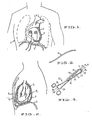
- the chest region of the human body shown in the drawings is designated in its entirety by the letter “C” and is illustrated to show the pericardium “P", the heart “H”, the diaphragm “D” and the forward rib cage “R”.
- an electrode “E1” is shown posteriorly positioned within the pericardium and electrode “E2” is shown anteriorly positioned within the pericardium.
- the electrodes "E1" and “E2” shown in Figs. 1 and 2 have been placed through means of the method and apparatus of the present invention. The process for this placement is described in detail in the following discussion.
- the curved probe shown in Fig. 3 is designated in its entirety by the numeral 10.
- This probe is fabricated of a rigid material, such a stainless steel, and finished so as to have a smooth exterior surface. Its purpose, as will become more apparent from the following discussion is to enable a surgeon to dissect a tunnel between the pericardium and diaphragm through a subxiphoid incision formed in the chest wall.
- the preferred embodiment intrapericardial access apparatus of Fig. 4 is designated in its entirely by the numeral 12.
- This apparatus is of a forceps construction embodying upper and lower elongate jaw elements 14 and 16, respectively, similar to those used for tenaculum forceps.
- the jaw elements are hingedly secured together for movement toward and away from each other by a hinge pin 18.
- the distal ends of the jaw elements 14 and 16 are formed with rigid aligned lateral extensions 20 and 22, respectively. These extensions, as will become more apparent from the following discussion, are pointed and provided to clampingly engage the tissue of the pericardium therebetween.
- Handles 24 and 26 are rigidly affixed to the jaw elements 14 and 16, respectively, and terminate in thumb and finger rings.
- Interengageable ratchet elements 28 and 30 are formed on the handles 24 and 26 to selectively lock the handles in a condition wherein the extensions 20 and 22 are clampingly engaged with pericardial tissue.
- a first primary open-ended tubular guide 32 is fixed to and extends over the outer side of the jaw element 14 and terminates in a open distal end 34 extending laterally of the element.
- a second open-ended tubular guide 36 is fixed to and extends over the jaw element 16 and terminates in an open distal end 38 extending laterally of that element.
- the ends 34 and 38 are axially aligned when the jaw elements are clampingly engaged with the pericardial tissue and, in the preferred embodiment, are of such relative diameters that the end 38 may fit within the end 34.
- the edges of the ends may be sharpened to cut through the pericardial tissue upon being clamped into engagement therewith.
- a secondary open-ended tubular guide 40 is fixed to and extends along the guide 32.
- the guide 40 terminates in a bias cut open end short of the distal end 34.
- the purpose of the secondary lumen is to provide additional access into the interior of the pericardium for the insertion of instruments such as: a secondary guide wire; an irrigation catheter; or a fiberoptic scope.
- Figs. 5 to 15a sequentially illustrate the steps of the inventive method in the process of accessing the interior of the pericardium and implanting defibrillator electrodes within the pericardium to the posterior and anterior of the heart.
- a subxiphoid incision 42 is formed in the chest wall. The method of the invention is then carried out through the following steps:
- the electrode may be held in place with a crimpable annular button 58 (Fig. 15B) of the type disclosed in copending application S.N. 120,590.
- a section of the second cannula, designated 56a is left in place around the electrode "E2” and the button is crimped into engagement with this section and sutured to the wall of the pericardium.
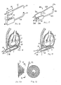
- the first alternative embodiment of the access apparatus shown in Fig. 16 is designated in its entirety by the numeral "60".
- This apparatus comprises: an upper jaw element 62 of an open-ended tubular configuration having an open distal end 64 extending laterally therefrom; a lower jaw element 66 of an open-ended tubular configuration having an open distal end 68 extending laterally therefrom; a T-shaped block 70 fixed to the element 62, said block including a tongue-like extension 72; and, a block 74 fixed to the jaw element 66 and having a socket 76 therein for complimental receipt of the tongue-like extension 72.
- the blocks 70 and 74 are so positioned relative to the elements 62 and 66 that the distal ends 64 and 68 assume an axially aligned condition when the extension 72 is received within the socket 76.
- the element 62 is so proportioned relative to the element 66 that the distal end 64 may be received within the distal end 66 when the extension 72 and groove 76 are complimentally engaged.
- the apparatus 60 is used in a manner corresponding to that of the apparatus 12, with the exception that the jaw elements of the apparatus 60 may be inserted into place individually and that the apparatus includes no pointed lateral extensions, such as the extensions 20 and 22 .
- Figs. 18 and 19 show the manner in which the apparatus 60 would be placed to extend a guide wire through the lower wall of the pericardium. It should be appreciated that the guide wire 50 would be provided with a sharpened tip and extended from the upper jaw element 62 through pericardium and into the lower jaw element 66.
- the second alternative embodiment apparatus of Fig. 17 is designated in its entirety by the numeral "60 a ".
- the parts of the apparatus "60 a " are similar to those of the apparatus “60” and designated by like numerals, followed by the subscript “a” as follows: upper jaw element 62 a ; open distal end 64 a ; lower jaw element 66 a ; open distal end 68 a ; block 70 a ; tongue-like extension 72 a ; block 74 a ; and socket 76 a .
- the block 70 a is pivotally secured to the block 74 a by a hinge pin 78 and is moveable about this pin between the open condition illustrated in Fig. 17 and a closed condition wherein the distal end 74 a is received within the distal end 68 a .
- the operation of the apparatus 60 a corresponds to that of the apparatus 60, with the exception that the surgeon has the option of inserting the apparatus into place as shown in Fig. 18 with the blocks 70 a and 74 a hingedly interconnected. Alternatively, he may insert them individually and hingedly secure them together after they are in place.
- the present invention provides a method and apparatus whereby intrapericardial access may be provided with minimal surgery and risk of physical trauma to the heart. It should be understood, however, that the invention is not intended to be limited to the specifics of the described embodiments, but rather is defined by the accompanying claims.
Landscapes
- Health & Medical Sciences (AREA)
- Heart & Thoracic Surgery (AREA)
- Radiology & Medical Imaging (AREA)
- Engineering & Computer Science (AREA)
- Biomedical Technology (AREA)
- Nuclear Medicine, Radiotherapy & Molecular Imaging (AREA)
- Cardiology (AREA)
- Life Sciences & Earth Sciences (AREA)
- Animal Behavior & Ethology (AREA)
- General Health & Medical Sciences (AREA)
- Public Health (AREA)
- Veterinary Medicine (AREA)
- Electrotherapy Devices (AREA)
- Surgical Instruments (AREA)
- Percussion Or Vibration Massage (AREA)
Abstract
Intrapericardial access is provided by clamping the wall of the pericardium between elongate jaw elements carrying axially aligned tubular guides and passing a guide wire through the guides and the pericardial tissue therebetween. In the preferred embodiment the jaw elements include interengageable ratchets for holding the elements in clamping engagement with the wall of the pericardium and aligned pointed extensions for piercing the pericardial tissue clamped between the elements. Further intrapericardial access is provided by an additional tubular guide carried by the jaw element intended to be disposed in the pericardium during placement of the guide wire.
Description
- The present invention relates to a method and apparatus for providing intrapericardial access with a minimal amount of surgery and, more particularly, is concerned with an improved technique for extending a guide wire through the pericardial wall. In its more specific aspects, the invention is concerned with an improved method for implanting defibrillation electrodes within the pericardium.
- Numerous efforts have been made to introduce implantable electrodes with a minimal amount of surgery. These efforts have affected placement both intrapericardially and extrapericardially. Where intrapericardial placement was provided, however, the prior art efforts have risked physical trauma to the heart during placement. The present invention is designed to minimize this risk.
- The method of the present invention provides access to the interior of the pericardium through an incision in the inferior border of the pericardium and a tunnel dissected between the pericardium and the diaphragm. In the method, one jaw of a clamp-like placement device is extended interiorly of the pericardium through the incision and the other jaw is extended exteriorly of the pericardium through the tunnel. The jaws include tubular guide elements with aligned open distal ends curved toward one another. Once placed relative to the pericardium, the jaw elements are moved to clamp the tissue of the pericardium therebetween. A guide wire is then extended through the tubular elements and the pericardial tissue therebetween. Once the wire is so placed, the clamp-like device is removed, leaving the wire in place to facilitate access to the interior of the pericardium.
- In the method of placing an electrode within the pericardium, a guide cannula is extended over the wire and into the pericardium. A primary electrode is then passed through the cannula and into the interior of the pericardium. A secondary electrode may be inserted through the incision in the inferior border of the pericardium.
- The apparatus of the invention comprises the clamp-like placement device, including first and second elongate jaw elements, each of which has an open-ended tubular guide extending over the length thereof and terminating in an open distal end extending laterally of the element. It further comprises means for securing the jaw elements together in a condition wherein the open distal ends of the tubular guides are in aligned closely disposed relationship to one another. In the preferred embodiment, the apparatus further comprises means for holding the jaw elements in clamping engagement with opposite sides of pericardial tissue and a secondary open-ended tubular guide secured to and extending along at least one of the jaw elements.
- A principal object of the invention is to provide a method and apparatus for accessing the interior of the pericardium with a minimum of surgery and risk of physical trauma to the heart.
- Another and more specific object of the invention is to provide such a method and apparatus for extending a guide wire through the pericardial wall, without risk that the wire will effect physical trauma on the heart.
- Still another object of the invention is to provide an improved method for guiding an implantable defibrillator electrode into the pericardium.
- Yet another object of the invention is to provide an apparatus having a simple mode of operation which may be used to pass a guide wire into the pericardium with a minimum of surgery.
- A more specific object of the invention is to provide such an apparatus having means to create a puncture through the wall of the pericardium.
- A further object of the invention is to provide such an apparatus having a secondary lumen adapted to be used for the introduction of other elements into the pericardium.
- These and other objects will become more apparent when viewed in light of the following detailed description and accompanying drawings.
-
- Fig. 1 is a front prospective view of the upper chest region of a human body, with parts thereof shown in section, illustrating the electrodes of a defibrillator which have been implanted in the pericardium through use of the method and apparatus of the invention;
- Fig. 2 is a cross-sectional side view of the body of Fig. 1;
- Fig. 3 is a side elevational view of a curved probe which may be used to dissect a tunnel between the pericardium and diaphragm in the method of the present invention;
- Fig. 4 is a perspective view illustrating a preferred embodiment of the intrapericardial access apparatus;
- Figs. 5 to 15a are cross-sectional side views of the upper region of a human body, sequentially illustrating the steps of practicing the present invention to first access the interior of the pericardium and then place defibrillator electrodes therein;
- Fig. 15b is a cross-sectional elevational view, with parts thereof broken away, illustrating a modification of the arrangement shown in Fig. 15a, wherein the electrode within the anterior pericardial space is secured to the pericardium through means of a crimpable button;
- Fig. 16 is an exploded perspective view of a first alternative embodiment of the intrapericardial access apparatus;
- Fig. 17 is a perspective view of a second alternative embodiment of the intrapericardial access apparatus;
- Fig. 18 is a cross-sectional view of the chest region of a human body, illustrating the first alternative embodiment access apparatus in the process of being positioned to extend to either side of the lower wall of the pericardium;
- Fig. 19 is a cross-sectional elevational view similar to Fig. 18, illustrating the first alternative embodiment access apparatus in the process of being used to extend a guide wire through the lower wall of the pericardium;
- Fig. 20 is a side elevational view of a coiled electrode which may be placed through means of the method and apparatus of the present invention; and,
- Fig. 21 is a front elevational view of the Fig. 20 electrode, taken on the plane designated by line 21-21 of Fig. 20.
- The chest region of the human body shown in the drawings is designated in its entirety by the letter "C" and is illustrated to show the pericardium "P", the heart "H", the diaphragm "D" and the forward rib cage "R". As shown in Figs. 1 and 2, an electrode "E₁" is shown posteriorly positioned within the pericardium and electrode "E₂" is shown anteriorly positioned within the pericardium. The electrodes "E₁" and "E₂" shown in Figs. 1 and 2 have been placed through means of the method and apparatus of the present invention. The process for this placement is described in detail in the following discussion.
- The curved probe shown in Fig. 3 is designated in its entirety by the
numeral 10. This probe is fabricated of a rigid material, such a stainless steel, and finished so as to have a smooth exterior surface. Its purpose, as will become more apparent from the following discussion is to enable a surgeon to dissect a tunnel between the pericardium and diaphragm through a subxiphoid incision formed in the chest wall. - The preferred embodiment intrapericardial access apparatus of Fig. 4 is designated in its entirely by the
numeral 12. This apparatus is of a forceps construction embodying upper and lowerelongate jaw elements hinge pin 18. The distal ends of thejaw elements lateral extensions 20 and 22, respectively. These extensions, as will become more apparent from the following discussion, are pointed and provided to clampingly engage the tissue of the pericardium therebetween.Handles jaw elements Interengageable ratchet elements handles extensions 20 and 22 are clampingly engaged with pericardial tissue. - A first primary open-ended
tubular guide 32 is fixed to and extends over the outer side of thejaw element 14 and terminates in a opendistal end 34 extending laterally of the element. A second open-endedtubular guide 36 is fixed to and extends over thejaw element 16 and terminates in an opendistal end 38 extending laterally of that element. Theends end 38 may fit within theend 34. The edges of the ends may be sharpened to cut through the pericardial tissue upon being clamped into engagement therewith. - A secondary open-ended tubular guide 40 is fixed to and extends along the
guide 32. The guide 40 terminates in a bias cut open end short of thedistal end 34. The purpose of the secondary lumen is to provide additional access into the interior of the pericardium for the insertion of instruments such as: a secondary guide wire; an irrigation catheter; or a fiberoptic scope. - Figs. 5 to 15a sequentially illustrate the steps of the inventive method in the process of accessing the interior of the pericardium and implanting defibrillator electrodes within the pericardium to the posterior and anterior of the heart. At the outset of the procedure, a
subxiphoid incision 42 is formed in the chest wall. The method of the invention is then carried out through the following steps: - 1. A pair of clamps or
forceps 44 are used to pick up the inferior border of the pericardium "P" through the subxiphoid incision (Fig. 5). This is carried out under direct vision. - 2. A curved probe, such as the
probe 10 is used to dissect a tunnel "T" between the pericardium "P" and the diaphragm "D", towards the posterior aspect of the pericardium (Fig. 6). This is also carried out under direct vision, while the inferior border of the pericardium is held by theforceps 44. - 3. A small nick 46 is cut through the inferior border of the pericardium (Fig. 7). This is carried out under direct vision, using a
scalpel 48 while the border of the pericardium is held with theclamp 44. - 4. The
intrapericardial access apparatus 12 is inserted through theincision 44 to extend thelower jaw element 16 into the tunnel "T" and theupper jaw element 14 into the pericardium through the nick 46 (Fig. 8). This step is carried out while the inferior border of the pericardium is held by theforceps 44, with the jaw elements of theapparatus 12 sufficiently spread to pass to either side of the lower wall of the pericardium. - 5. The jaw elements of the access apparatus are snapped together, trapping the tissue of the pericardium between them (Fig. 9). During this process, the pointed
lateral extensions 20 and 22 on the elements pierce and grip surface of the tissue, thus gripping and stabilizing the apparatus relative to the pericardium. Theratchet elements - 6. The next step is to pass a guide wire into the pericardium and through the lower pericardial wall (Fig. 10). Depending upon the choice of the surgeon, this may be achieved by slightly different techniques. In one, a guide wire with a sharpened tip is extended through the upper
tubular guide 32 to exit therefrom and pierce through the pericardial wall and pass into the lowertubular guide 36, from whence it is extended out through the subxiphoid incision. In another, after the apparatus is locked in place, it is moved back and forth to form a somewhat enlarged opening in the pericardial wall where it is pierced by theextensions 20 and 22 and then the apparatus is pulled backwards to position the distal ends of the tubular guides 36 and 38 in alignment with this hole. The guide wire, designated 50, is then extended through the innertubular guide 32, passed through the enlarged opening, and exited our through the outertubular guide 32. In yet another, sharpenededges tabular guide 32, through the hole and into the lowertabular guide 36. The latter technique does not require a sharpened tip on the guide wire. Regardless of which technique is used, theguide wire 50 is passed from the intrapericardial to the extrapericardial portion of the apparatus to prevent any chance of myocardial injury should the wire pass outside of the placement apparatus. - 7. The
intrapericardial access apparatus 12 is unsnapped and removed, leaving theguide wire 50 in place (Fig. 11). As so placed, the guide wire may be used for accessing the interior of the pericardium for any desired purpose. The steps hereinafter set forth are for the purpose of introducing defibrillation electrodes into the intrapericardial space. - 8. A
dilator 52 andcannula 54 are threaded over the guide wire, through the extrapericardial tunnel "T" into the intrapericardial space (Fig. 12). During this step, the dilator is first extended through the hole pierced in the lower wall of the pericardium to enlarge this hole and the cannula is then extended thereover and through the hole. Thereafter the dilator is withdrawn, leaving the cannula in place. - 9. With the
cannula 54 in place, thedilator 52 is removed and the electrode "E₁" is advanced through the cannula into position in the posterior intrapericardial space (Fig. 13). The electrode "E₁" may be of the resilient helical coil type disclosed in copending application S.N. 129,124, filed November 12, 1987. Such electrodes are capable of being straightened into a generally rectilinear configuration to facilitate advancing them through a cannula and, when released, assume a three-dimensional helical coil configuration as may be seen in Figs. 20 and 21 herein. - 10. After the posterior electrode "E₁" is in place, the
cannula 54 is removed and a second cannula 56 having the electrode "E₂" threaded therethrough is advanced into the anterior pericardial space through the inferior pericardial nick or incision 46 (Fig. 14). - 11. The electrode "E" is passed through the cannula 56 to unfurl into the anterior pericardial space and the cannula 56 is then removed (Fig. 15A). The nick 46 is then closed with a suture, thus securing the electrode "E₂" in place. The electrode "E₁" is held in position by virtue of its passage through the tunnel "T" between the pericardium and the diaphragm.
- As an alternative to suturing the anterior electrode "E₂" in place as described above, the electrode may be held in place with a crimpable annular button 58 (Fig. 15B) of the type disclosed in copending application S.N. 120,590. With this arrangement, a section of the second cannula, designated 56a, is left in place around the electrode "E₂" and the button is crimped into engagement with this section and sutured to the wall of the pericardium.
- The first alternative embodiment of the access apparatus shown in Fig. 16 is designated in its entirety by the numeral "60". This apparatus comprises: an
upper jaw element 62 of an open-ended tubular configuration having an opendistal end 64 extending laterally therefrom; alower jaw element 66 of an open-ended tubular configuration having an opendistal end 68 extending laterally therefrom; a T-shapedblock 70 fixed to theelement 62, said block including a tongue-like extension 72; and, a block 74 fixed to thejaw element 66 and having asocket 76 therein for complimental receipt of the tongue-like extension 72. Theblocks 70 and 74 are so positioned relative to theelements extension 72 is received within thesocket 76. Theelement 62 is so proportioned relative to theelement 66 that thedistal end 64 may be received within thedistal end 66 when theextension 72 andgroove 76 are complimentally engaged. - The
apparatus 60 is used in a manner corresponding to that of theapparatus 12, with the exception that the jaw elements of theapparatus 60 may be inserted into place individually and that the apparatus includes no pointed lateral extensions, such as theextensions 20 and 22. Figs. 18 and 19 show the manner in which theapparatus 60 would be placed to extend a guide wire through the lower wall of the pericardium. It should be appreciated that theguide wire 50 would be provided with a sharpened tip and extended from theupper jaw element 62 through pericardium and into thelower jaw element 66. - The second alternative embodiment apparatus of Fig. 17 is designated in its entirety by the numeral "60 a ". The parts of the apparatus "60 a " are similar to those of the apparatus "60" and designated by like numerals, followed by the subscript "a" as follows:
upper jaw element 62 a ; opendistal end 64 a ;lower jaw element 66 a ; opendistal end 68 a ;block 70 a ; tongue-like extension 72 a ; block 74 a ; andsocket 76 a . Theblock 70 a is pivotally secured to the block 74 a by a hinge pin 78 and is moveable about this pin between the open condition illustrated in Fig. 17 and a closed condition wherein the distal end 74 a is received within thedistal end 68 a . - The operation of the
apparatus 60a corresponds to that of theapparatus 60, with the exception that the surgeon has the option of inserting the apparatus into place as shown in Fig. 18 with theblocks 70 a and 74 a hingedly interconnected. Alternatively, he may insert them individually and hingedly secure them together after they are in place. - From the foregoing detailed description, it is believed apparent that the present invention provides a method and apparatus whereby intrapericardial access may be provided with minimal surgery and risk of physical trauma to the heart. It should be understood, however, that the invention is not intended to be limited to the specifics of the described embodiments, but rather is defined by the accompanying claims.
Claims (29)
1. A method for implanting an electrode within the interior of the pericardium, comprising the steps of:
(a) creating a subxiphoid incision;
(b) dissecting a tunnel between the pericardium and the diaphragm from the subxiphoid incision towards the posterior aspect of the pericardium;
(c) making a pericardial incision in the inferior border of the pericardium;
(d) providing a clamp-like placement device having elongate tubular jaws with aligned open distal ends curved toward one another;
(e) passing one of the jaws through the pericardial incision to locate the curved end of said one jaw at a posterior position within the pericardium;
(f) passing the other of the jaws into the tunnel to the exterior of the pericardium to locate the curved end of said other jaw in alignment with the curved end of said one jaw;
(g) passing a guide wire through the jaws to extend the wire within and through the pericardium;
(h) removing the placement device while leaving the guide wire in place;
(i) extending a cannula over the wire within the tunnel to pass the cannula through the tunnel and into the pericardium; and,
(j) passing an electrode through the cannula and into the pericardium to one side of the heart.
2. A method according to Claim 1 wherein the electrode is a first electrode and the cannula through which it is passed is a first cannula; further comprising the steps of extending a second cannula into the pericardium through the pericardial incision and passing a second electrode into the pericardium through the second cannula so as to position said second electrode on the opposite side of the heart from the first electrode.
3. A method according to Claim 2 further comprising the step of fastening the second electrode to the pericardium or the surrounding connective tissue to hold the second electrode in a generally fixed position within the pericardium.
4. A method according to Claim 3, wherein the step of fastening the second electrode to the pericardium or the surrounding connective tissue comprises the steps of:
(a) sliding a crimping ring over the electrode;
(b) attaching said ring to the pericardium or the surrounding tissue; and,
(c) crimping the ring to firmly grasp the electrode therein.
5. A method according to Claim 4, wherein:
(a) a section of the cannula is left in place between the electrode and button as the crimping ring is slid over the electrode; and,
(b) the crimping ring is crimped onto the cannula to compress the cannula into gripping engagement with the electrode.
6. A method according to Claim 1 further comprising the step of removing the guide wire after the cannula has been extended thereover.
7. A method according to Claim 6 further comprising the step of removing the cannula while leaving the electrode in place within the pericardium.
8. A method according to Claim 1 wherein the guide wire has a sharpened tip and is passed first through said one jaw to pierce the pericardium and then enter into and pass through said other jaw.
9. A method according to Claim 1 wherein:
(a) the elongate jaws of the placement device include aligned distal end portions capable of clamping the pericardium therebetween and forming a puncture in the pericardium;
(b) after the jaws are passed into place said aligned distal end portions are clamped on the pericardium to form a puncture therein; and,
(c) after the puncture is formed the placement device is moved to align the distal ends of the tubular jaws with the puncture and the guide wire is then passed through the jaws and passes through the puncture to extend through the pericardium.
10. A method according to Claim 1, wherein:
(a) the open distal ends of the tubular jaws are sharpened;
(b) after the jaws are passed into place said open distal ends are clamped on the pericardium to cut a hole therethrough; and,
(c) after the hole is formed the guide wire is passed through the jaws and passes through the hole to extend through the pericardium.
11. A method for accessing the interior of the pericardium, comprising the steps of:
(a) creating a subxiphoid incision;
(b) dissecting a tunnel between the pericardium and the diaphragm from the subxiphoid incision towards the posterior aspect of the pericardium;
(c) making a pericardial incision in the inferior border of the pericardium;
(d) providing a clamp-like placement device having elongate tubular jaws with aligned open distal ends curved toward one another;
(e) passing one of the jaws through the pericardial incision to locate the curved end of said one jaw within the pericardium proximate to and interior surface thereof;
(f) passing the other of the jaws into the tunnel to the exterior of the pericardium to locate the curved end of said other jaw proximate to an exterior surface of the pericardium in alignment with the curved end of said one jaw;
(g) passing a guide wire through the jaws to extend the wire within and through the pericardium; and,
(h) removing the placement device while leaving the guide wire in place.
12. A method according to Claim 11 wherein the guide wire has a sharpened tip and is passed first through said one jaw to pierce the pericardium and then enter into and pass through said other jaw.
13. A method according to Claim 11 wherein:
(d) the elongate jaws of the placement device include aligned distal end portions capable of clamping the pericardium therebetween and forming a puncture in the pericardium;
(a) after the jaws are passed into place said aligned distal end portions are clamped on the pericardium to form a puncture therein; and,
(b) after the puncture is formed the placement device is moved to align the distal ends of the tubular jaws with the puncture and the guide wire is then passed through the jaws and passes through the puncture to extend through the pericardium.
14. A method according to Claim 11, wherein:
(a) the open distal ends of the tubular jaws are sharpened;
(b) after the jaws are passed into place said open distal ends are clamped on the pericardium to cut a hole therethrough; and,
(c) after the hole is formed the guide wire is passed through the jaws and passes through the hole to extend through the pericardium.
15. Intrapericardial access apparatus comprising:
(a) first and second elongate jaw elements, said elements each having a primary open ended tubular guide extending over at least a portion of the length thereof and terminating in an open distal end extending laterally of the element; and,
(b) means for securing the elements together in a condition wherein the open distal ends of the tubular guides are in aligned closely disposed relationship with one another.
16. Apparatus according to Claim 15 further comprising a secondary open ended tubular guide secured to and extending along at least one of said jaw elements, said secondary tubular guide extending generally parallel to and terminating short of the distal end of the primary tubular element secured to said one jaw element.
17. Apparatus according to Claim 15 wherein the means for securing the jaw elements together comprises a hinge connection between the elements.
18. Apparatus according to Claim 17, further comprising a handle secured to each jaw element and extending beyond the hinge connection between the elements to facilitate selective movement of the jaw elements toward and away from one other.
19. Apparatus according to Claim 15 wherein one of the jaw elements is adapted to be extended intrapericardially and the other of the jaw elements is adapted to be extended extrapericardially; the apparatus further comprising means for holding the jaw elements with the distal ends of the primary guides aligned in clamping engagement with opposite sides of pericardial tissue therebetween.
20. Apparatus according to Claim 19 further comprising sharpened edges on the distal ends of the primary guides to cut a hole through pericardial tissue upon being clamped into engagement with opposite sides of the tissue.
21. Apparatus according to Claim 18 wherein one of the jaw elements is adapted to be extended intrapericardially and the other of the jaw elements is adapted to be extended extrapericardially; the apparatus further comprising means for holding the jaw elements with the distal ends of the primary guides aligned in clamping engagement with opposite sides of pericardial tissue therebetween.
22. Apparatus according to Claim 20 wherein the means for holding the jaw elements with the distal ends of the primary guides in clamping engagement with pericardial tissue comprises interengageable ratchet elements on the handles.
23. Apparatus according to Claim 15 further comprising a lateral extension on each of the jaw elements, said extensions being disposed to clampingly engage pericardial tissue therebetween when the jaw elements are secured together in the condition with the distal ends of the tubular guides in closely adjacent aligned relationship.
24. Apparatus according to Claim 23 wherein the lateral extensions are disposed closely adjacent the open distal ends of the guides.
25. Apparatus according to Claim 24 further comprising a secondary open ended tubular guide secured to and extending along at least one of at least one of said jaw elements, said secondary tubular guide extending generally parallel to and terminating short of the distal end of the primary tubular element secured to said one jaw element.
26. Apparatus according to Claim 24 wherein the means for securing the jaw elements together comprises a hinge connection between the elements.
27. Apparatus according to Claim 26, further comprising a handle secured to each jaw element and extending beyond the hinge connection between the elements to facilitate selective movement of the jaw elements toward and away from one other.
28. Apparatus according to Claim 27 wherein one of the jaw elements is adapted to be extended intrapericardially and the other of the jaw elements is adapted to be extended extrapericardially; the apparatus further comprising means for holding the jaw elements with the lateral extensions thereof in clamping engagement with opposite sides of pericardial tissue therebetween.
29. Apparatus according to Claim 28 wherein the means for holding the lateral extensions of the jaw elements in clamping engagement with pericardial tissue comprises interengageable ratchet elements on the handles.
Applications Claiming Priority (2)
| Application Number | Priority Date | Filing Date | Title |
|---|---|---|---|
| US404957 | 1989-09-08 | ||
| US07/404,957 US5033477A (en) | 1987-11-13 | 1989-09-08 | Method and apparatus for providing intrapericardial access and inserting intrapericardial electrodes |
Publications (2)
| Publication Number | Publication Date |
|---|---|
| EP0417031A2 true EP0417031A2 (en) | 1991-03-13 |
| EP0417031A3 EP0417031A3 (en) | 1993-03-17 |
Family
ID=23601714
Family Applications (1)
| Application Number | Title | Priority Date | Filing Date |
|---|---|---|---|
| EP19900630153 Withdrawn EP0417031A3 (en) | 1989-09-08 | 1990-09-06 | Improved method and apparatus for providing intrapericardial access and inserting intrapericardial electrodes |
Country Status (4)
| Country | Link |
|---|---|
| US (1) | US5033477A (en) |
| EP (1) | EP0417031A3 (en) |
| JP (1) | JPH03236833A (en) |
| CA (1) | CA2024901A1 (en) |
Cited By (10)
| Publication number | Priority date | Publication date | Assignee | Title |
|---|---|---|---|---|
| US5397342A (en) * | 1993-06-07 | 1995-03-14 | Cardiac Pacemakers, Inc. | Resilient structurally coupled and electrically independent electrodes |
| EP0665030A2 (en) * | 1994-01-28 | 1995-08-02 | Thomas J. Fogarty | Improved implantable defibrillator electrodes and methods of implanting same |
| WO1998024378A1 (en) * | 1996-12-05 | 1998-06-11 | Comedicus Incorporated | Apparatus and method for accessing the pericardial space |
| EP1017321A1 (en) * | 1997-02-13 | 2000-07-12 | Boston Scientific Limited | Percutaneous and hiatal devices and methods for use in minimally invasive pelvic surgery |
| US6162195A (en) * | 1995-06-07 | 2000-12-19 | Cormedics Corp. | Method and apparatus for accessing the pericardial space |
| US6231518B1 (en) | 1998-05-26 | 2001-05-15 | Comedicus Incorporated | Intrapericardial electrophysiological procedures |
| US6689047B2 (en) | 2000-11-15 | 2004-02-10 | Scimed Life Systems, Inc. | Treating urinary incontinence |
| US8033983B2 (en) | 2001-03-09 | 2011-10-11 | Boston Scientific Scimed, Inc. | Medical implant |
| US8162816B2 (en) | 2001-03-09 | 2012-04-24 | Boston Scientific Scimed, Inc. | System for implanting an implant and method thereof |
| US8632453B2 (en) | 2002-12-17 | 2014-01-21 | Boston Scientific Scimed, Inc. | Spacer for sling delivery system |
Families Citing this family (80)
| Publication number | Priority date | Publication date | Assignee | Title |
|---|---|---|---|---|
| US5269326A (en) * | 1991-10-24 | 1993-12-14 | Georgetown University | Method for transvenously accessing the pericardial space via the right auricle for medical procedures |
| US5524619A (en) * | 1993-04-01 | 1996-06-11 | Terumo Kabushiki Kaisha | Multielectrode probe |
| WO1997016169A1 (en) * | 1995-11-01 | 1997-05-09 | Chiron Corporation | Treatment of a cardiovascular indication by delivery of therapeutics to the pericardial space |
| US5904711A (en) * | 1996-02-08 | 1999-05-18 | Heartport, Inc. | Expandable thoracoscopic defibrillation catheter system and method |
| US5968010A (en) * | 1997-04-30 | 1999-10-19 | Beth Israel Deaconess Medical Center, Inc. | Method for transvenously accessing the pericardial space via the right atrium |
| US20040215168A1 (en) * | 1997-04-30 | 2004-10-28 | Beth Israel Deaconess Medical Center | Kit for transvenously accessing the pericardial space via the right atrium |
| US6200303B1 (en) | 1997-04-30 | 2001-03-13 | Beth Israel Deaconess Medical Center, Inc. | Method and kit for transvenously accessing the pericardial space via the right atrium |
| US6096037A (en) | 1997-07-29 | 2000-08-01 | Medtronic, Inc. | Tissue sealing electrosurgery device and methods of sealing tissue |
| US6296630B1 (en) | 1998-04-08 | 2001-10-02 | Biocardia, Inc. | Device and method to slow or stop the heart temporarily |
| US6488689B1 (en) | 1999-05-20 | 2002-12-03 | Aaron V. Kaplan | Methods and apparatus for transpericardial left atrial appendage closure |
| US7526342B2 (en) * | 1999-08-10 | 2009-04-28 | Maquet Cardiovascular Llc | Apparatus for endoscopic cardiac mapping and lead placement |
| US20030187460A1 (en) * | 1999-08-10 | 2003-10-02 | Chin Albert K. | Methods and apparatus for endoscopic cardiac surgery |
| US7398781B1 (en) * | 1999-08-10 | 2008-07-15 | Maquet Cardiovascular, Llc | Method for subxiphoid endoscopic access |
| US7288096B2 (en) * | 2003-01-17 | 2007-10-30 | Origin Medsystems, Inc. | Apparatus for placement of cardiac defibrillator and pacer |
| US20030187461A1 (en) * | 1999-08-10 | 2003-10-02 | Chin Albert K. | Releasable guide and method for endoscopic cardiac lead placement |
| US7597698B2 (en) * | 1999-08-10 | 2009-10-06 | Maquet Cardiovascular Llc | Apparatus and method for endoscopic encirclement of pulmonary veins for epicardial ablation |
| US6607547B1 (en) | 1999-08-25 | 2003-08-19 | Origin Medsystems, Inc. | Longitudinal dilator and method |
| US6569082B1 (en) | 1999-08-10 | 2003-05-27 | Origin Medsystems, Inc. | Apparatus and methods for cardiac restraint |
| US20040102804A1 (en) * | 1999-08-10 | 2004-05-27 | Chin Albert K. | Apparatus and methods for endoscopic surgical procedures |
| US20060287574A1 (en) * | 1999-08-25 | 2006-12-21 | Chin Albert K | Longitudinal dilator |
| US6447443B1 (en) | 2001-01-13 | 2002-09-10 | Medtronic, Inc. | Method for organ positioning and stabilization |
| US6478776B1 (en) | 2000-04-05 | 2002-11-12 | Biocardia, Inc. | Implant delivery catheter system and methods for its use |
| US6546935B2 (en) | 2000-04-27 | 2003-04-15 | Atricure, Inc. | Method for transmural ablation |
| US20020107514A1 (en) | 2000-04-27 | 2002-08-08 | Hooven Michael D. | Transmural ablation device with parallel jaws |
| US6905498B2 (en) | 2000-04-27 | 2005-06-14 | Atricure Inc. | Transmural ablation device with EKG sensor and pacing electrode |
| US6932811B2 (en) | 2000-04-27 | 2005-08-23 | Atricure, Inc. | Transmural ablation device with integral EKG sensor |
| US20040138621A1 (en) | 2003-01-14 | 2004-07-15 | Jahns Scott E. | Devices and methods for interstitial injection of biologic agents into tissue |
| US7628780B2 (en) | 2001-01-13 | 2009-12-08 | Medtronic, Inc. | Devices and methods for interstitial injection of biologic agents into tissue |
| US7740623B2 (en) | 2001-01-13 | 2010-06-22 | Medtronic, Inc. | Devices and methods for interstitial injection of biologic agents into tissue |
| JP2003007916A (en) * | 2001-06-19 | 2003-01-10 | Sanyo Electric Co Ltd | Method of manufacturing circuit device |
| US7967816B2 (en) | 2002-01-25 | 2011-06-28 | Medtronic, Inc. | Fluid-assisted electrosurgical instrument with shapeable electrode |
| EP1496956B1 (en) * | 2002-04-11 | 2011-04-06 | Medtronic Vascular, Inc. | Devices for transluminal or transthoracic interstitial electrode placement |
| US7610104B2 (en) | 2002-05-10 | 2009-10-27 | Cerebral Vascular Applications, Inc. | Methods and apparatus for lead placement on a surface of the heart |
| US7291161B2 (en) * | 2002-10-02 | 2007-11-06 | Atricure, Inc. | Articulated clamping member |
| WO2004045675A2 (en) * | 2002-11-15 | 2004-06-03 | Pressure Products Medical Supplies, Inc. | A method and apparatus for anchoring of pacing leads |
| US20040138521A1 (en) * | 2003-01-10 | 2004-07-15 | Grabek James R. | Myocardial constraint |
| US7162309B2 (en) * | 2003-04-07 | 2007-01-09 | Medtronic, Inc. | Epicardial lead delivery system and method |
| US7288092B2 (en) * | 2003-04-23 | 2007-10-30 | Atricure, Inc. | Method and apparatus for ablating cardiac tissue with guide facility |
| US7361138B2 (en) | 2003-07-31 | 2008-04-22 | Scimed Life Systems, Inc. | Bioabsorbable casing for surgical sling assembly |
| US7846168B2 (en) | 2003-10-09 | 2010-12-07 | Sentreheart, Inc. | Apparatus and method for the ligation of tissue |
| US20050113901A1 (en) * | 2003-10-24 | 2005-05-26 | Cardiac Pacemakers, Inc. | Myocardial lead attachment system |
| US7530980B2 (en) | 2004-04-14 | 2009-05-12 | Atricure, Inc | Bipolar transmural ablation method and apparatus |
| US20050234507A1 (en) * | 2004-04-16 | 2005-10-20 | Jeff Geske | Medical tool for access to internal tissue |
| EP1750608B1 (en) | 2004-06-02 | 2012-10-03 | Medtronic, Inc. | Ablation device with jaws |
| US7981065B2 (en) * | 2004-12-20 | 2011-07-19 | Cardiac Pacemakers, Inc. | Lead electrode incorporating extracellular matrix |
| US8060219B2 (en) | 2004-12-20 | 2011-11-15 | Cardiac Pacemakers, Inc. | Epicardial patch including isolated extracellular matrix with pacing electrodes |
| US8029528B2 (en) * | 2005-01-03 | 2011-10-04 | Atricure, Inc. | Instrument guide and method for use |
| US20060149121A1 (en) * | 2005-01-03 | 2006-07-06 | Hughett James D Sr | Instrument guide and method for use |
| US7918865B2 (en) | 2005-04-07 | 2011-04-05 | Sentreheart, Inc. | Apparatus and method for the ligation of tissue |
| US7272448B1 (en) | 2005-05-24 | 2007-09-18 | Pacesetter, Inc. | Medical lead for placement in the pericardial sac |
| US20070043416A1 (en) * | 2005-08-19 | 2007-02-22 | Cardiac Pacemakers, Inc. | Implantable electrode array |
| US8244379B2 (en) * | 2006-04-26 | 2012-08-14 | Medtronic, Inc. | Pericardium fixation concepts of epicardium pacing leads and tools |
| US8036757B2 (en) | 2006-09-10 | 2011-10-11 | Seth Worley | Pacing lead and method for pacing in the pericardial space |
| WO2008118737A1 (en) * | 2007-03-22 | 2008-10-02 | University Of Virginia Patent Foundation | Electrode catheter for ablation purposes and related method thereof |
| WO2008112870A2 (en) | 2007-03-13 | 2008-09-18 | University Of Virginia Patent Foundation | Epicardial ablation catheter and method of use |
| US9468396B2 (en) | 2007-03-19 | 2016-10-18 | University Of Virginia Patent Foundation | Systems and methods for determining location of an access needle in a subject |
| US11058354B2 (en) | 2007-03-19 | 2021-07-13 | University Of Virginia Patent Foundation | Access needle with direct visualization and related methods |
| WO2008115745A2 (en) | 2007-03-19 | 2008-09-25 | University Of Virginia Patent Foundation | Access needle pressure sensor device and method of use |
| PL2142107T3 (en) | 2007-03-30 | 2013-06-28 | Sentreheart Inc | Devices and systems for closing the left atrial appendage |
| US20080294175A1 (en) * | 2007-05-21 | 2008-11-27 | Epitek, Inc. | Left atrial appendage closure |
| WO2008147678A1 (en) * | 2007-05-21 | 2008-12-04 | Epitek, Inc. | Left atrial appendage closure |
| US7881810B1 (en) | 2007-05-24 | 2011-02-01 | Pacesetter, Inc. | Cardiac access methods and apparatus |
| EP2214563B1 (en) | 2007-09-20 | 2017-04-19 | Sentreheart, Inc. | Devices and methods for remote suture management |
| WO2009062061A1 (en) | 2007-11-09 | 2009-05-14 | University Of Virginia Patent Foundation | Steerable epicardial pacing catheter system placed via the subxiphoid process |
| JP2010029564A (en) * | 2008-07-30 | 2010-02-12 | Olympus Corp | Defibrillation electrode, defibrillator and endoscope |
| US8332641B2 (en) * | 2009-01-30 | 2012-12-11 | Freescale Semiconductor, Inc. | Authenticated debug access for field returns |
| ES2705473T3 (en) | 2009-04-01 | 2019-03-25 | Sentreheart Inc | Tissue ligation device and controls thereof |
| US9642534B2 (en) | 2009-09-11 | 2017-05-09 | University Of Virginia Patent Foundation | Systems and methods for determining location of an access needle in a subject |
| EP2537149B1 (en) | 2010-02-18 | 2017-10-25 | University Of Virginia Patent Foundation | System, method, and computer program product for simulating epicardial electrophysiology procedures |
| CA2796267A1 (en) | 2010-04-13 | 2011-10-20 | Sentreheart, Inc. | Methods and devices for treating atrial fibrillation |
| JP2012075604A (en) * | 2010-09-30 | 2012-04-19 | Olympus Corp | Therapeutic instrument |
| CN103747751B (en) | 2011-06-08 | 2016-12-28 | 森特里心脏股份有限公司 | Knot of tissue bundling device and tensioner thereof |
| WO2014164028A1 (en) | 2013-03-12 | 2014-10-09 | Sentreheart, Inc. | Tissue ligation devices and methods therefor |
| EP4226881A1 (en) | 2013-10-31 | 2023-08-16 | AtriCure, Inc. | Device for left atrial appendage closure |
| US11096736B2 (en) * | 2013-12-09 | 2021-08-24 | Biosense Webster (Israel) Ltd. | Pericardial catheter with temperature sensing array |
| WO2016100948A1 (en) | 2014-12-19 | 2016-06-23 | Cardiac Pacemakers, Inc. | Medical lead anchoring |
| US10130369B2 (en) | 2015-03-24 | 2018-11-20 | Sentreheart, Inc. | Tissue ligation devices and methods therefor |
| EP4282371A3 (en) | 2015-03-24 | 2024-03-06 | AtriCure, Inc. | Devices for left atrial appendage closure |
| BR112018010622B1 (en) | 2015-11-25 | 2023-04-11 | Talon Medical, LLC | FABRIC COUPLING DEVICE AND KIT |
| CA3015804A1 (en) | 2016-02-26 | 2017-08-31 | Sentreheart, Inc. | Devices and methods for left atrial appendage closure |
Citations (3)
| Publication number | Priority date | Publication date | Assignee | Title |
|---|---|---|---|---|
| FR1539593A (en) * | 1967-10-06 | 1968-09-13 | Pinching and suturing surgical instrument | |
| US4312337A (en) * | 1980-09-08 | 1982-01-26 | Donohue Brian T | Cannula and drill guide apparatus |
| GB2214814A (en) * | 1988-01-28 | 1989-09-13 | Bio Medical Eng | Surgical apparatus for guiding a wire or suture in a loop |
Family Cites Families (8)
| Publication number | Priority date | Publication date | Assignee | Title |
|---|---|---|---|---|
| US3866615A (en) * | 1973-01-15 | 1975-02-18 | Daigle Claude W | Portable electronic cardiac stimulator |
| US4030509A (en) * | 1975-09-30 | 1977-06-21 | Mieczyslaw Mirowski | Implantable electrodes for accomplishing ventricular defibrillation and pacing and method of electrode implantation and utilization |
| US4291707A (en) * | 1979-04-30 | 1981-09-29 | Mieczyslaw Mirowski | Implantable cardiac defibrillating electrode |
| US4270549A (en) * | 1979-04-30 | 1981-06-02 | Mieczyslaw Mirowski | Method for implanting cardiac electrodes |
| US4548203A (en) * | 1982-06-01 | 1985-10-22 | Purdue Research Foundation | Sequential-pulse, multiple pathway defibrillation method |
| US4567900A (en) * | 1984-06-04 | 1986-02-04 | Moore J Paul | Internal deployable defibrillator electrode |
| US4865037A (en) * | 1987-11-13 | 1989-09-12 | Thomas J. Fogarty | Method for implanting automatic implantable defibrillator |
| US4884567A (en) * | 1987-12-03 | 1989-12-05 | Dimed Inc. | Method for transvenous implantation of objects into the pericardial space of patients |
-
1989
- 1989-09-08 US US07/404,957 patent/US5033477A/en not_active Expired - Fee Related
-
1990
- 1990-09-06 EP EP19900630153 patent/EP0417031A3/en not_active Withdrawn
- 1990-09-06 JP JP2234661A patent/JPH03236833A/en active Pending
- 1990-09-07 CA CA002024901A patent/CA2024901A1/en not_active Abandoned
Patent Citations (3)
| Publication number | Priority date | Publication date | Assignee | Title |
|---|---|---|---|---|
| FR1539593A (en) * | 1967-10-06 | 1968-09-13 | Pinching and suturing surgical instrument | |
| US4312337A (en) * | 1980-09-08 | 1982-01-26 | Donohue Brian T | Cannula and drill guide apparatus |
| GB2214814A (en) * | 1988-01-28 | 1989-09-13 | Bio Medical Eng | Surgical apparatus for guiding a wire or suture in a loop |
Cited By (29)
| Publication number | Priority date | Publication date | Assignee | Title |
|---|---|---|---|---|
| US5397342A (en) * | 1993-06-07 | 1995-03-14 | Cardiac Pacemakers, Inc. | Resilient structurally coupled and electrically independent electrodes |
| EP0665030A2 (en) * | 1994-01-28 | 1995-08-02 | Thomas J. Fogarty | Improved implantable defibrillator electrodes and methods of implanting same |
| EP0665030A3 (en) * | 1994-01-28 | 1998-01-14 | Thomas J. Fogarty | Improved implantable defibrillator electrodes and methods of implanting same |
| US6666844B1 (en) | 1995-06-07 | 2003-12-23 | Stephen R. Igo | Method and apparatus for accessing the pericardial space |
| US6162195A (en) * | 1995-06-07 | 2000-12-19 | Cormedics Corp. | Method and apparatus for accessing the pericardial space |
| WO1998024378A1 (en) * | 1996-12-05 | 1998-06-11 | Comedicus Incorporated | Apparatus and method for accessing the pericardial space |
| US5931810A (en) * | 1996-12-05 | 1999-08-03 | Comedicus Incorporated | Method for accessing the pericardial space |
| US6156009A (en) * | 1996-12-05 | 2000-12-05 | Comedicus Incorporated | Apparatus for accessing the pericardial space |
| US7413540B2 (en) | 1997-02-13 | 2008-08-19 | Boston Scientific Scimed, Inc. | Devices for minimally invasive pelvic surgery |
| US8636641B2 (en) | 1997-02-13 | 2014-01-28 | Boston Scientific Scimed, Inc. | Devices for minimally invasive pelvic surgery |
| US6423080B1 (en) | 1997-02-13 | 2002-07-23 | Scimed Life Systems, Inc. | Percutaneous and hiatal devices and methods for use in minimally invasive pelvic surgery |
| EP1017321A4 (en) * | 1997-02-13 | 2001-04-11 | Boston Scient Ltd | Percutaneous and hiatal devices and methods for use in minimally invasive pelvic surgery |
| US9314323B2 (en) | 1997-02-13 | 2016-04-19 | Boston Scientific Scimed, Inc. | Systems, devices and methods for minimally invasive pelvic surgery |
| US6752814B2 (en) | 1997-02-13 | 2004-06-22 | Scimed Life Systems, Inc. | Devices for minimally invasive pelvic surgery |
| EP1017321A1 (en) * | 1997-02-13 | 2000-07-12 | Boston Scientific Limited | Percutaneous and hiatal devices and methods for use in minimally invasive pelvic surgery |
| US7614999B2 (en) | 1997-02-13 | 2009-11-10 | Boston Scientific Scimed, Inc. | Systems, devices, and methods for minimally invasive pelvic surgery |
| US7621865B2 (en) | 1997-02-13 | 2009-11-24 | Boston Scientific Scimed, Inc. | Systems, devices, and methods for minimally invasive pelvic surgery |
| US7691050B2 (en) | 1997-02-13 | 2010-04-06 | Boston Scientific Scimed, Inc. | Devices for minimally invasive pelvic surgery |
| US7691052B2 (en) | 1997-02-13 | 2010-04-06 | Boston Scientific Scimed, Inc. | Devices for minimally invasive pelvic surgery |
| US8814777B2 (en) | 1997-02-13 | 2014-08-26 | Boston Scientific Scimed, Inc. | Devices for minimally invasive pelvic surgery |
| US8790238B2 (en) | 1997-02-13 | 2014-07-29 | Boston Scientific Scimed, Inc. | Systems, devices, and methods for minimally invasive pelvic surgery |
| US8172744B2 (en) | 1997-02-13 | 2012-05-08 | Boston Scientific Scimed, Inc. | Devices for minimally invasive pelvic surgery |
| US8727962B2 (en) | 1997-02-13 | 2014-05-20 | Boston Scientific Scimed, Inc. | Devices for minimally invasive pelvic surgery |
| US6231518B1 (en) | 1998-05-26 | 2001-05-15 | Comedicus Incorporated | Intrapericardial electrophysiological procedures |
| US6689047B2 (en) | 2000-11-15 | 2004-02-10 | Scimed Life Systems, Inc. | Treating urinary incontinence |
| US8617048B2 (en) | 2001-03-09 | 2013-12-31 | Boston Scientific Scimed, Inc. | System for implanting an implant and method thereof |
| US8162816B2 (en) | 2001-03-09 | 2012-04-24 | Boston Scientific Scimed, Inc. | System for implanting an implant and method thereof |
| US8033983B2 (en) | 2001-03-09 | 2011-10-11 | Boston Scientific Scimed, Inc. | Medical implant |
| US8632453B2 (en) | 2002-12-17 | 2014-01-21 | Boston Scientific Scimed, Inc. | Spacer for sling delivery system |
Also Published As
| Publication number | Publication date |
|---|---|
| CA2024901A1 (en) | 1991-03-09 |
| US5033477A (en) | 1991-07-23 |
| EP0417031A3 (en) | 1993-03-17 |
| JPH03236833A (en) | 1991-10-22 |
Similar Documents
| Publication | Publication Date | Title |
|---|---|---|
| US5033477A (en) | Method and apparatus for providing intrapericardial access and inserting intrapericardial electrodes | |
| US5071428A (en) | Method and apparatus for providing intrapericardial access and inserting intrapericardial electrodes | |
| US20200155353A1 (en) | Cartridge for an electrode array insertion device | |
| US5236435A (en) | Laparoscopic surgical staple system | |
| US5464447A (en) | Implantable defibrillator electrodes | |
| US5536255A (en) | Dilator/introducer apparatus for percutaneous gastrostomy | |
| EP0517494B1 (en) | Insertion and tunneling tool for a subcutaneous wire patch electrode | |
| US7063708B2 (en) | Insertion tool system for an electrode array | |
| US5904692A (en) | Needle assembly and method for passing suture | |
| JPH01148276A (en) | Method and apparatus for embedding automatic fibrillation remover | |
| EP0140557A2 (en) | Surgical instrument | |
| EP0656191A2 (en) | Surgical clip applier | |
| EP0687446A2 (en) | Surgical incision members for endoscopic suturing apparatus | |
| CA1135142A (en) | Suture forming tool | |
| WO1995021574A1 (en) | Laparoscopic suturing technique and associated device | |
| US20190231353A1 (en) | Hemostasis clip | |
| WO1998046142A9 (en) | Needle assembly and method for passing suture | |
| US4966143A (en) | Surgical wire guide | |
| US6702739B2 (en) | Holder | |
| US5127421A (en) | Implantation of leads | |
| JPH08500755A (en) | Method for implanting a cardiac defibrillation electrode and applicator device therefor | |
| US4574805A (en) | Instrument for skin surgery and method for using same | |
| WO2019208896A1 (en) | Coupling structure of coil spring pdo and needle tube | |
| AU604722B2 (en) | Marlin thoracic catheter |
Legal Events
| Date | Code | Title | Description |
|---|---|---|---|
| PUAI | Public reference made under article 153(3) epc to a published international application that has entered the european phase |
Free format text: ORIGINAL CODE: 0009012 |
|
| AK | Designated contracting states |
Kind code of ref document: A2 Designated state(s): DE FR GB |
|
| PUAL | Search report despatched |
Free format text: ORIGINAL CODE: 0009013 |
|
| AK | Designated contracting states |
Kind code of ref document: A3 Designated state(s): DE FR GB |
|
| STAA | Information on the status of an ep patent application or granted ep patent |
Free format text: STATUS: THE APPLICATION IS DEEMED TO BE WITHDRAWN |
|
| 18D | Application deemed to be withdrawn |
Effective date: 19921001 |