EP0416947B1 - Boronized sliding material and method for producing the same - Google Patents
Boronized sliding material and method for producing the same Download PDFInfo
- Publication number
- EP0416947B1 EP0416947B1 EP19900309842 EP90309842A EP0416947B1 EP 0416947 B1 EP0416947 B1 EP 0416947B1 EP 19900309842 EP19900309842 EP 19900309842 EP 90309842 A EP90309842 A EP 90309842A EP 0416947 B1 EP0416947 B1 EP 0416947B1
- Authority
- EP
- European Patent Office
- Prior art keywords
- porosity
- region
- sintered
- boronized
- sliding material
- Prior art date
- Legal status (The legal status is an assumption and is not a legal conclusion. Google has not performed a legal analysis and makes no representation as to the accuracy of the status listed.)
- Expired - Lifetime
Links
Images

Classifications
-
- C—CHEMISTRY; METALLURGY
- C23—COATING METALLIC MATERIAL; COATING MATERIAL WITH METALLIC MATERIAL; CHEMICAL SURFACE TREATMENT; DIFFUSION TREATMENT OF METALLIC MATERIAL; COATING BY VACUUM EVAPORATION, BY SPUTTERING, BY ION IMPLANTATION OR BY CHEMICAL VAPOUR DEPOSITION, IN GENERAL; INHIBITING CORROSION OF METALLIC MATERIAL OR INCRUSTATION IN GENERAL
- C23C—COATING METALLIC MATERIAL; COATING MATERIAL WITH METALLIC MATERIAL; SURFACE TREATMENT OF METALLIC MATERIAL BY DIFFUSION INTO THE SURFACE, BY CHEMICAL CONVERSION OR SUBSTITUTION; COATING BY VACUUM EVAPORATION, BY SPUTTERING, BY ION IMPLANTATION OR BY CHEMICAL VAPOUR DEPOSITION, IN GENERAL
- C23C8/00—Solid state diffusion of only non-metal elements into metallic material surfaces; Chemical surface treatment of metallic material by reaction of the surface with a reactive gas, leaving reaction products of surface material in the coating, e.g. conversion coatings, passivation of metals
- C23C8/04—Treatment of selected surface areas, e.g. using masks
-
- B—PERFORMING OPERATIONS; TRANSPORTING
- B22—CASTING; POWDER METALLURGY
- B22F—WORKING METALLIC POWDER; MANUFACTURE OF ARTICLES FROM METALLIC POWDER; MAKING METALLIC POWDER; APPARATUS OR DEVICES SPECIALLY ADAPTED FOR METALLIC POWDER
- B22F3/00—Manufacture of workpieces or articles from metallic powder characterised by the manner of compacting or sintering; Apparatus specially adapted therefor ; Presses and furnaces
- B22F3/10—Sintering only
- B22F3/11—Making porous workpieces or articles
- B22F3/1103—Making porous workpieces or articles with particular physical characteristics
- B22F3/1109—Inhomogenous pore distribution
-
- C—CHEMISTRY; METALLURGY
- C23—COATING METALLIC MATERIAL; COATING MATERIAL WITH METALLIC MATERIAL; CHEMICAL SURFACE TREATMENT; DIFFUSION TREATMENT OF METALLIC MATERIAL; COATING BY VACUUM EVAPORATION, BY SPUTTERING, BY ION IMPLANTATION OR BY CHEMICAL VAPOUR DEPOSITION, IN GENERAL; INHIBITING CORROSION OF METALLIC MATERIAL OR INCRUSTATION IN GENERAL
- C23C—COATING METALLIC MATERIAL; COATING MATERIAL WITH METALLIC MATERIAL; SURFACE TREATMENT OF METALLIC MATERIAL BY DIFFUSION INTO THE SURFACE, BY CHEMICAL CONVERSION OR SUBSTITUTION; COATING BY VACUUM EVAPORATION, BY SPUTTERING, BY ION IMPLANTATION OR BY CHEMICAL VAPOUR DEPOSITION, IN GENERAL
- C23C8/00—Solid state diffusion of only non-metal elements into metallic material surfaces; Chemical surface treatment of metallic material by reaction of the surface with a reactive gas, leaving reaction products of surface material in the coating, e.g. conversion coatings, passivation of metals
- C23C8/02—Pretreatment of the material to be coated
-
- C—CHEMISTRY; METALLURGY
- C23—COATING METALLIC MATERIAL; COATING MATERIAL WITH METALLIC MATERIAL; CHEMICAL SURFACE TREATMENT; DIFFUSION TREATMENT OF METALLIC MATERIAL; COATING BY VACUUM EVAPORATION, BY SPUTTERING, BY ION IMPLANTATION OR BY CHEMICAL VAPOUR DEPOSITION, IN GENERAL; INHIBITING CORROSION OF METALLIC MATERIAL OR INCRUSTATION IN GENERAL
- C23C—COATING METALLIC MATERIAL; COATING MATERIAL WITH METALLIC MATERIAL; SURFACE TREATMENT OF METALLIC MATERIAL BY DIFFUSION INTO THE SURFACE, BY CHEMICAL CONVERSION OR SUBSTITUTION; COATING BY VACUUM EVAPORATION, BY SPUTTERING, BY ION IMPLANTATION OR BY CHEMICAL VAPOUR DEPOSITION, IN GENERAL
- C23C8/00—Solid state diffusion of only non-metal elements into metallic material surfaces; Chemical surface treatment of metallic material by reaction of the surface with a reactive gas, leaving reaction products of surface material in the coating, e.g. conversion coatings, passivation of metals
- C23C8/60—Solid state diffusion of only non-metal elements into metallic material surfaces; Chemical surface treatment of metallic material by reaction of the surface with a reactive gas, leaving reaction products of surface material in the coating, e.g. conversion coatings, passivation of metals using solids, e.g. powders, pastes
- C23C8/62—Solid state diffusion of only non-metal elements into metallic material surfaces; Chemical surface treatment of metallic material by reaction of the surface with a reactive gas, leaving reaction products of surface material in the coating, e.g. conversion coatings, passivation of metals using solids, e.g. powders, pastes only one element being applied
- C23C8/68—Boronising
- C23C8/70—Boronising of ferrous surfaces
Definitions
- the present invention relates to boronized sliding material and a method for producing the same. More particularly, the present invention relates to sintered sliding material, a part of which is boronized, and to a method for producing the same.
- Boronizing is widely applied to steel materials which have undergone rolling, forging, and casting, so as to improve the wear-resistance, oxidation-resistance, and corrosion-resistance thereof. While boronizing exhibits such improved properties, it has a drawback in that embrittlement occurs due to the hardness and brittleness of the borides. A very brittle layer of FeB is likely to form particularly on the treated surface. FeB readily cracks ad embrittles, so that the material, on which FeB is formed, is inappropriate for use as sliding material.
- the sintered material is usually used as is.
- the sintered material may occasionally be subjected to post-treatment, such as rolling, wire-drawing, swaging, forging, rolling, sizing or coining.
- post-treatment such as rolling, wire-drawing, swaging, forging, rolling, sizing or coining.
- coining the sintered material is placed in a die and is rolled.
- Surface treatment of the sintered material is not usual.
- Material standard FN-0200-T stipulated in MPIF (Metal Powder Institute Federation) specification relates to a case-hardenable material, which is characterized by addition of Ni and by a relatively high density in the range of from 7.2 to 7.6.
- SMF 2 stipulated in JPMA (Japan Powder Metallurgy Association) specification relates to material which is carburizable. Cu added in an amount of 3 % or less makes the pores to disappear and hence creates the carburizing property.
- Japanese Unexamined Patent Publication No. 60-21371 relates to a boronizing method. According to this method, a metallic container filled with Cr powder is compressed. The Cr powder is then sintered under such a condition that no pinholes are formed, and hence the sintered body has true density. Machining is then carried out to remove the container to obtain a wrought material. This wrought material having no pinholes, is then boronized. The method, therefore, is not the boronizing of sintered material.
- Case-hardening or carburizing of sintered material has heretofore been known, whereby the sintered material as a whole is hardened.
- hardening a part of the surface of the sintered material, such as the inner surface of a tubular material, by boronizing has not been possible.
- the inner surface of a tubular sintered material was subjected to boronizing.
- the boronizing gas which was in the generally generated amount, passed through the pores and leaked toward the outer surface of the tubular sintered material. Since boronizing in itself was impossible, the desired treated layer was evidently not formed on the inner surface.
- the boronizing was carried out while generating a large amount of the boronizing gas, not only the surface but also the interior of the sintered body were boronized.
- a considerable amount of brittle FeB is formed on the surface of the pores which are present in the interior of the sintered body. The sintered body was therefore embrittled as a whole by the boronizing.
- a sintered ferrous sliding material comprising a boronized surface region having a first porosity of 5% or less and comprising a 10-150 »m thick boride layer at least partially therein, and an interior region having a second porosity of less than 30% and higher than the first porosity, the boride being exposed on the boronized surface region and being essentially not formed in the interior region.
- a method for producing the sintered sliding material comprising the steps of preparing a sintered ferrous material having a second porosity of less than 30%: applying a pressure to at least a selected part of the surface of the sintered ferrous material, so as to decrease the porosity of the selected surface to a first porosity of 5% or less, smaller than the second porosity; and, boronizing at least the selected parts of the surface with a boronizing agent to form a sliding material with a 10-150 »m thick boride layer.
- the mother materials to be boronized may be such various ferrous materials as sintered iron, and sintered ferrous alloy materials based on Fe-C, Fe-C-Cu, Fe-Ni, Fe-Ni-Cu, Fe-Mn, and Fe-C-Mn with or without S additive.
- the boronizing method which can be used in the present invention may be any one of the solid, liquid and gas methods, but the solid method is particularly preferred.
- the boride phase is thinly formed, by the boronizing, on the inner or outer surface of a tubular sintered body where the wear-resistance is to be imparted.
- the boride phase is also thinly formed, by the boronizing, on a surface of a sheet where the wear-resistance is to be imparted.
- the surface of the sliding material which does not slide against the opposite member and hence is not required to be wear-resistant, should be desirably free of the boride, with the result that reduction of fatigue strength and the like due to the presence of the boride is lessened as much as possible.
- the porosity of the surface region of the sliding material according to the present invention is lower than that of the interior region and is less than 5 %. This is because, if the porosity of the surface region exceeds 5 %, the boronizing gas leaks to the interior of the sintered body. When this happens, the desired surface is not boronized. Occasionally, the boronizing is possible, but even a deep part of the interior region or the interior region as a whole is boronized, with the result that brittle FeB is formed widely in the interior, and hence the sliding material embrittles. In addition, if the porosity of the surface is the same as that of the interior, stress is liable to concentrate on the boronized surface. In this case, the load resistance is impaired or the interior region is liable to embrittle depending upon the porosity.
- the porosity of the surface region is preferably 2 % or more for the following reasons.
- the porosity of the surface region is in the range of from 2 to 5 %, only a trace amount of the boronizing gas is leaked. This leads to the boronizing of the desired surface and also to enhancement of the boronizing speed at the initial stage because the boronizing gas fills the pores in the surface region.
- expansion of the sintered material occurs and the pores of the surface region gradually diminish.
- the boride then fills the pores of the surface region. The leakage amount is therefore further reduced, so that the boronizing of the interior is further prevented.
- the porosity of the surface region is 2 % or more, the pressure required for forming the surface region is advantageously lower than in the case of forming the surface region having porosity of less than 2 %.
- the equipment for applying the pressure is uncomplicated and inexpensive.
- the surface region has preferably a thickness of from 0.05 to 2 mm, more preferably from 0.1 to 1 mm, most preferably 0.2 to 0.6 mm.
- the best thickness is approximately 0.5 mm.
- an intermediate region having porosity greater than 5 % but smaller than that of the interior region is formed between the two regions.
- the porosity of the intermediate region is adjusted by means of applying pressure to the sintered body.
- the porosity of the interior region remains unchanged by the pressure application.
- the porosity of the intermediate region in the proximity of the surface region and the interior region is preferably close to those of the two regions, respectively.
- the porosity of the intermediate region preferably gradually decreases from the one to the other of the above-mentioned ones.
- the intermediate and interior regions enable a higher load resistance to be attained than that attained only by the interior region.
- the intermediate region is preferably from 0.5 to 1.5 mm in thickness.
- the sum of the intermediate and surface regions is preferably from 2 mm or less.
- the boride phase is preferably formed only in the surface region but may be formed also in the surface part of the intermediate region in the case where the surface region is thin.
- the porosity of the interior region is so high, preferably 6 % or more, that it is not boronized.
- the interior region is boronized, the FeB layer is not removed by grinding, and hence the sliding material is brittle.
- Such sliding material exhibits a low load resistance, because the surface of the pores cracks when the sliding material is subjected to load.
- a non-boronized interior region having the high porosity as described above behaves as a cushion when the sliding material is subjected to load. The load resistance is therefore enhanced.
- the porosity of the interior region is very low, the powder metallurgical conditions for obtaining a high sintered body become severe.
- the porosity of the interior region becomes very high, for example 30 % or more, the strength is so low as to make the sintered body inappropriate for the sliding member.
- the porosity value of the interior region described above indicates the average value of the values varying in the interior region from the border in contact with the surface region to the surface opposite to the boronized surface.
- the distribution of porosity of the interior region should preferably be such that porosity is smaller at the part nearer the surface and greater at the more inner part.
- the intermediate region is preferably formed so as to provide a homogeneous distribution of the strain in the interior region.
- the intermediate region has preferably a thickness of from 0.5 to 1.5 mm and has porosity between those of the surface region and the interior region, for example from 6 to 15 %.
- the boride phase When the load, to which the sliding material is subjected, is low, the boride phase may be formed such that it intrudes slightly, i.e., several tens of »m, into the interior region.
- the thickness of the boride phase is controlled such that it is less than the surface region, and hence, the non-boronized surface region free of boride remains beneath the boronized surface region.
- the boride phase, the surface region without the boride phase (hereinafter referred to as "the intermediate layer"), and the interior region are successively formed beneath the surface of the sliding member.
- the intermediate layer When such sliding member is subjected to load, the intermediate layer as a whole transmits the stress uniformly to the interior region, since the intermediate layer has a high density or a low porosity. That is, such intermediate layer has a high strength and, therefore, it has no weak portion where stress is liable to concentrate; hence the force is transmitted to the whole intermediate layer. Contrary to this, when the boride phase is in direct contact with the interior region, stress concentration is liable to take place at such contact point, which easily incurs local transmission of the stress to the interior region and destruction of the sliding member.
- the surface region is preferably thicker than the boride layer described in the following.
- the boride layer is partly removed by a thickness of a few microns, i.e., the brittle FeB formed on the surface of the sliding member is removed, by means of grinding and the like.
- the sintered material which has been boronized and then treated as described above, is used as the sliding member.
- a dual phase of Fe2B and Fe3B may appear on the surface where the FeB phase has been removed.
- the thickness of the boride layer is from 10 to 150 »m, preferably from 30 to 100 »m.
- the wear-resistance is poor.
- the thickness of the boride layer exceeds 150 »m, a large amount of brittle FeB is formed, and shape distortion of the sliding member becomes likely to occur due to the boronizing.
- shape distortion occurs, the interior of the boride layer is subjected to deformation, which makes the strength reduction likely to occur.
- the sintered material whose porosity of the surface part is different from that of the interior region, is produced by means of sintering by a conventional method to provide a sintered body having virtually uniform porosity throughout the body and then applying pressure to the sintered body.
- Specific methods for diminishing the pores are rolling, die-pressing, and die-forming with rotary discs. Any other method may be used.
- sizing is usually performed in order to preserve the life of jigs. The sizing is preferably carried out such that the size of a workpiece is decreased by approximately from 3 to 10 %. When size reduction by sizing is less than 3 %, the effects due to the size reduction are slight. On the other hand, working exceeding 10 % size reduction is difficult.
- the working method of sizing is dependent upon the shape of the workpiece.
- a workpiece is tubular
- the inner surface of the tubular workpiece is subjected to ironing by means of a die in the form of a mandrel tapered front end, so as to diminish the pores of the inner surface
- the outer surface of the tubular workpiece is subjected to ironing by means of a tubular die, so as to diminish the pores on the outer surface.
- the sintered material can be boronized without incurring embrittlement due to borides, because the porosities of the surface region and the interior region are set as described above.
- the sintered material is partially boronized, with the result that the sintered sliding material having improved wear-resistance, oxidation-resistance, load-resistance, and fatigue-resistance is provided.
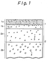
- Fig. 1 is a schematic drawing of the boronized surface of sintered sliding material in the inventive Example 1.
- Figs. 2 and 3 are the metal photographs of the boronized surface in the inventive Example 1.
- Sintered material was produced by sintering SMF3030 (Fe-C based sintered material) stipulated in JPMA specification for sintered material for mechanical and constructional use.
- the density of the sintered material was 7.0 g/cm3, which corresponded to porosity of 16 %.
- the shape of the sintered material was cylindrical, 20 mm in the inner diameter and 40 mm in the outer diameter.
- the inner surface of the tubular sintered material was subjected to the sizing to decrease the inner diameter to 19.2 mm, namely, the sizing dimension was 0.8 mm and the sizing ratio was 4 %. Subsequently, the sintered material was boronized at 900 °C for 1 hour.
- the boronizing agent used was a powder mixture consisting of 3 to 20 parts of B4C, 50 to 80 parts of SiC, 10 to 30 parts of C, and from 0.5 to 7 parts of potassium borofluoride. This powder mixture was brought into contact with only the surface to be boronized. The boronizing was so carried out.
- pores 3 and the boride layer 1a of the boronized surface are schematically illustrated.
- a part of the FeB phase formed on the top surface of the boronized material was removed by grinding and is not shown in Fig. 1.
- the surface region is denoted by 1 and has a thickness of 0.5 mm.
- the intermediate region is denoted by 2a.
- the border between the boride layer 1a and the mother material is in a zigzag pattern.
- the thickness of the boride layer herein is the average thickness measured at the average position of the convexities and concavities.
- the surface region 1 (0.5 mm thick) had a porosity of 4 %.
- the porosities of the interior region 2b and the intermediate region 2a (1.0 mm thick) were 16% and 7 % respectively (at the center of the region 2a).
- the pores in the regions 1a, 1b, 2a, which were affected by sizing, were bonded or deformed and diminished to a thin elongated shape. As a result, the porosity in the surface region 1 and intermediate region 2a was decreased by the sizing.
- the average thickness of the boride layer 1a was 50 »m. Metal microscopic photographs of the boride layer are shown in Fig. 2 (magnification of 100) and in Fig. 3 (magnification of 400). As is clear from Figs. 2 and 3, the boride layer is formed only on the surface of sintered material.
- the ferrous sintered material having 15 % of the porosity was not subjected to sizing but was directly boronized as a whole.
- the boronizing was carried out by the method of Example 1.
- the boride was formed on the surface of the sintered material and on the surface of the pores in the interior of the sintered material.
- the FeB was therefore present in the interior of the sintered material.
- the load resistance was tested under the following condition. Speed: 15m/sec Load: successive increase by 40 kgf/10 min Lubrication: oil-supply with a pad Opposed material: high Si-Al The seizure load was 410 kg/cm2 in Example 1, while the seizure load was 300 kg/cm2 in Comparative Example.
- the porosity of the surface region 1 was 2 %.
- the porosity of the interior region 2b was 16 %.
- the porosity of the intermediate region 2a (1 mm thick) varied from 6 to 15 %.
- the thickness of the boride layer 1a was 80 »m thick. The boronizing was carried out by the method described above. The boride layer was formed only on the inner surface of the tubular sintered material.
Landscapes
- Chemical & Material Sciences (AREA)
- Engineering & Computer Science (AREA)
- Mechanical Engineering (AREA)
- Chemical Kinetics & Catalysis (AREA)
- Materials Engineering (AREA)
- Metallurgy (AREA)
- Organic Chemistry (AREA)
- Manufacturing & Machinery (AREA)
- Powder Metallurgy (AREA)
- Sliding-Contact Bearings (AREA)
Description
- The present invention relates to boronized sliding material and a method for producing the same. More particularly, the present invention relates to sintered sliding material, a part of which is boronized, and to a method for producing the same.
- Boronizing is widely applied to steel materials which have undergone rolling, forging, and casting, so as to improve the wear-resistance, oxidation-resistance, and corrosion-resistance thereof. While boronizing exhibits such improved properties, it has a drawback in that embrittlement occurs due to the hardness and brittleness of the borides. A very brittle layer of FeB is likely to form particularly on the treated surface. FeB readily cracks ad embrittles, so that the material, on which FeB is formed, is inappropriate for use as sliding material.
- The sintered material is usually used as is. The sintered material may occasionally be subjected to post-treatment, such as rolling, wire-drawing, swaging, forging, rolling, sizing or coining. In coining, the sintered material is placed in a die and is rolled. Surface treatment of the sintered material is not usual.
- Prior art of the surface treatment of the sintered material is now surveyed.
- Material standard FN-0200-T stipulated in MPIF (Metal Powder Institute Federation) specification relates to a case-hardenable material, which is characterized by addition of Ni and by a relatively high density in the range of from 7.2 to 7.6. In addition, SMF 2 stipulated in JPMA (Japan Powder Metallurgy Association) specification relates to material which is carburizable. Cu added in an amount of 3 % or less makes the pores to disappear and hence creates the carburizing property.
- Japanese Unexamined Patent Publication No. 60-21371 relates to a boronizing method. According to this method, a metallic container filled with Cr powder is compressed. The Cr powder is then sintered under such a condition that no pinholes are formed, and hence the sintered body has true density. Machining is then carried out to remove the container to obtain a wrought material. This wrought material having no pinholes, is then boronized. The method, therefore, is not the boronizing of sintered material.
- Case-hardening or carburizing of sintered material has heretofore been known, whereby the sintered material as a whole is hardened. However, hardening a part of the surface of the sintered material, such as the inner surface of a tubular material, by boronizing has not been possible.
- According to an experiment by the present inventors, the inner surface of a tubular sintered material was subjected to boronizing. The boronizing gas, which was in the generally generated amount, passed through the pores and leaked toward the outer surface of the tubular sintered material. Since boronizing in itself was impossible, the desired treated layer was evidently not formed on the inner surface. When the boronizing was carried out while generating a large amount of the boronizing gas, not only the surface but also the interior of the sintered body were boronized. In addition, a considerable amount of brittle FeB is formed on the surface of the pores which are present in the interior of the sintered body. The sintered body was therefore embrittled as a whole by the boronizing.
- It is therefore an object of the present invention to provide a sintered sliding material having a boronized layer only on the desired surface, which material exhibits improved surface properties along with improved strength and load resistance.
- It is another object of the present invention to provide a method for producing the sintered sliding material mentioned above.
- In accordance with the objects of the present invention, there is provided a sintered ferrous sliding material comprising a boronized surface region having a first porosity of 5% or less and comprising a 10-150 »m thick boride layer at least partially therein, and an interior region having a second porosity of less than 30% and higher than the first porosity, the boride being exposed on the boronized surface region and being essentially not formed in the interior region.
- There is also provided a method for producing the sintered sliding material comprising the steps of preparing a sintered ferrous material having a second porosity of less than 30%: applying a pressure to at least a selected part of the surface of the sintered ferrous material, so as to decrease the porosity of the selected surface to a first porosity of 5% or less, smaller than the second porosity; and, boronizing at least the selected parts of the surface with a boronizing agent to form a sliding material with a 10-150 »m thick boride layer.
- The mother materials to be boronized may be such various ferrous materials as sintered iron, and sintered ferrous alloy materials based on Fe-C, Fe-C-Cu, Fe-Ni, Fe-Ni-Cu, Fe-Mn, and Fe-C-Mn with or without S additive. The boronizing method which can be used in the present invention may be any one of the solid, liquid and gas methods, but the solid method is particularly preferred. The boride phase is thinly formed, by the boronizing, on the inner or outer surface of a tubular sintered body where the wear-resistance is to be imparted. The boride phase is also thinly formed, by the boronizing, on a surface of a sheet where the wear-resistance is to be imparted. The surface of the sliding material, which does not slide against the opposite member and hence is not required to be wear-resistant, should be desirably free of the boride, with the result that reduction of fatigue strength and the like due to the presence of the boride is lessened as much as possible.
- The porosity of the surface region of the sliding material according to the present invention is lower than that of the interior region and is less than 5 %. This is because, if the porosity of the surface region exceeds 5 %, the boronizing gas leaks to the interior of the sintered body. When this happens, the desired surface is not boronized. Occasionally, the boronizing is possible, but even a deep part of the interior region or the interior region as a whole is boronized, with the result that brittle FeB is formed widely in the interior, and hence the sliding material embrittles. In addition, if the porosity of the surface is the same as that of the interior, stress is liable to concentrate on the boronized surface. In this case, the load resistance is impaired or the interior region is liable to embrittle depending upon the porosity.
- The porosity of the surface region is preferably 2 % or more for the following reasons. When the porosity of the surface region is in the range of from 2 to 5 %, only a trace amount of the boronizing gas is leaked. This leads to the boronizing of the desired surface and also to enhancement of the boronizing speed at the initial stage because the boronizing gas fills the pores in the surface region. As the boronizing advances, expansion of the sintered material occurs and the pores of the surface region gradually diminish. The boride then fills the pores of the surface region. The leakage amount is therefore further reduced, so that the boronizing of the interior is further prevented. A trace amount of the boronizing gas, which is leaked from the surface region to the interior, is exhausted through the porous interior to the exterior of the sintered body. Note the high porosity of the interior facilitates the exhaustion of the leaked gas. When the porosity of the surface region is 2 % or more, the pressure required for forming the surface region is advantageously lower than in the case of forming the surface region having porosity of less than 2 %. In addition, the equipment for applying the pressure is uncomplicated and inexpensive.
- The surface region has preferably a thickness of from 0.05 to 2 mm, more preferably from 0.1 to 1 mm, most preferably 0.2 to 0.6 mm. The best thickness is approximately 0.5 mm.
- According to a preferred embodiment of the present invention, an intermediate region having porosity greater than 5 % but smaller than that of the interior region is formed between the two regions. The porosity of the intermediate region is adjusted by means of applying pressure to the sintered body. The porosity of the interior region remains unchanged by the pressure application. The porosity of the intermediate region in the proximity of the surface region and the interior region is preferably close to those of the two regions, respectively. The porosity of the intermediate region preferably gradually decreases from the one to the other of the above-mentioned ones. The intermediate region described above is advantageous from the following points of view, that is; the bonding strength between the surface region and the interior region is enhanced; absorbability of load is enhanced; gas is easily exhausted; and the sintered material is easily produced.
- The intermediate and interior regions enable a higher load resistance to be attained than that attained only by the interior region. The intermediate region is preferably from 0.5 to 1.5 mm in thickness. The sum of the intermediate and surface regions is preferably from 2 mm or less. The boride phase is preferably formed only in the surface region but may be formed also in the surface part of the intermediate region in the case where the surface region is thin.
- The porosity of the interior region is so high, preferably 6 % or more, that it is not boronized. When the interior region is boronized, the FeB layer is not removed by grinding, and hence the sliding material is brittle. Such sliding material exhibits a low load resistance, because the surface of the pores cracks when the sliding material is subjected to load. A non-boronized interior region having the high porosity as described above behaves as a cushion when the sliding material is subjected to load. The load resistance is therefore enhanced. When the porosity of the interior region is very low, the powder metallurgical conditions for obtaining a high sintered body become severe. On the other hand, when the porosity of the interior region becomes very high, for example 30 % or more, the strength is so low as to make the sintered body inappropriate for the sliding member. The porosity value of the interior region described above indicates the average value of the values varying in the interior region from the border in contact with the surface region to the surface opposite to the boronized surface.
- The distribution of porosity of the interior region should preferably be such that porosity is smaller at the part nearer the surface and greater at the more inner part. When the porosity of the interior region is great, the intermediate region is preferably formed so as to provide a homogeneous distribution of the strain in the interior region. The intermediate region has preferably a thickness of from 0.5 to 1.5 mm and has porosity between those of the surface region and the interior region, for example from 6 to 15 %. The stress applied to a portion of the surface region is transmitted to the intermediate region bordering on the interior region. The stress is spread widely in the intermediate layer, because such layer is more dense than the surface region. The stress then transmitted to the interior region therefore does not locally concentrate.
- When the load, to which the sliding material is subjected, is low, the boride phase may be formed such that it intrudes slightly, i.e., several tens of »m, into the interior region. Preferably, the thickness of the boride phase is controlled such that it is less than the surface region, and hence, the non-boronized surface region free of boride remains beneath the boronized surface region. In this case, the boride phase, the surface region without the boride phase (hereinafter referred to as "the intermediate layer"), and the interior region are successively formed beneath the surface of the sliding member. When such sliding member is subjected to load, the intermediate layer as a whole transmits the stress uniformly to the interior region, since the intermediate layer has a high density or a low porosity. That is, such intermediate layer has a high strength and, therefore, it has no weak portion where stress is liable to concentrate; hence the force is transmitted to the whole intermediate layer. Contrary to this, when the boride phase is in direct contact with the interior region, stress concentration is liable to take place at such contact point, which easily incurs local transmission of the stress to the interior region and destruction of the sliding member. In this regard, the surface region is preferably thicker than the boride layer described in the following.
- The boride layer is partly removed by a thickness of a few microns, i.e., the brittle FeB formed on the surface of the sliding member is removed, by means of grinding and the like.
- The sintered material, which has been boronized and then treated as described above, is used as the sliding member. As is proposed in Japanese Patent Application No. 63-181671 (US Patent Application S.N. 369,974), a dual phase of Fe₂B and Fe₃B may appear on the surface where the FeB phase has been removed. The thickness of the boride layer is from 10 to 150 »m, preferably from 30 to 100 »m. When the thickness of the boride phase is less than 10 »m, the wear-resistance is poor. On the other hand, when the thickness of the boride layer exceeds 150 »m, a large amount of brittle FeB is formed, and shape distortion of the sliding member becomes likely to occur due to the boronizing. When shape distortion occurs, the interior of the boride layer is subjected to deformation, which makes the strength reduction likely to occur.
- The sintered material, whose porosity of the surface part is different from that of the interior region, is produced by means of sintering by a conventional method to provide a sintered body having virtually uniform porosity throughout the body and then applying pressure to the sintered body. Specific methods for diminishing the pores are rolling, die-pressing, and die-forming with rotary discs. Any other method may be used. However, sizing is usually performed in order to preserve the life of jigs. The sizing is preferably carried out such that the size of a workpiece is decreased by approximately from 3 to 10 %. When size reduction by sizing is less than 3 %, the effects due to the size reduction are slight. On the other hand, working exceeding 10 % size reduction is difficult. The working method of sizing is dependent upon the shape of the workpiece. For example, when a workpiece is tubular, the inner surface of the tubular workpiece is subjected to ironing by means of a die in the form of a mandrel tapered front end, so as to diminish the pores of the inner surface, or the outer surface of the tubular workpiece is subjected to ironing by means of a tubular die, so as to diminish the pores on the outer surface.
- As described above, the sintered material can be boronized without incurring embrittlement due to borides, because the porosities of the surface region and the interior region are set as described above. The sintered material is partially boronized, with the result that the sintered sliding material having improved wear-resistance, oxidation-resistance, load-resistance, and fatigue-resistance is provided.
- The present invention is described with reference to the examples and the drawings.
- Fig. 1 is a schematic drawing of the boronized surface of sintered sliding material in the inventive Example 1.
- Figs. 2 and 3 are the metal photographs of the boronized surface in the inventive Example 1.
- Sintered material was produced by sintering SMF3030 (Fe-C based sintered material) stipulated in JPMA specification for sintered material for mechanical and constructional use. The density of the sintered material was 7.0 g/cm³, which corresponded to porosity of 16 %. The shape of the sintered material was cylindrical, 20 mm in the inner diameter and 40 mm in the outer diameter. The inner surface of the tubular sintered material was subjected to the sizing to decrease the inner diameter to 19.2 mm, namely, the sizing dimension was 0.8 mm and the sizing ratio was 4 %. Subsequently, the sintered material was boronized at 900 °C for 1 hour. The boronizing agent used was a powder mixture consisting of 3 to 20 parts of B₄C, 50 to 80 parts of SiC, 10 to 30 parts of C, and from 0.5 to 7 parts of potassium borofluoride. This powder mixture was brought into contact with only the surface to be boronized. The boronizing was so carried out.
- Referring to Fig.1, pores 3 and the boride layer 1a of the boronized surface are schematically illustrated. A part of the FeB phase formed on the top surface of the boronized material was removed by grinding and is not shown in Fig. 1. The surface region is denoted by 1 and has a thickness of 0.5 mm. The intermediate region is denoted by 2a. The border between the boride layer 1a and the mother material is in a zigzag pattern. The thickness of the boride layer herein is the average thickness measured at the average position of the convexities and concavities.
- The surface region 1 (0.5 mm thick) had a porosity of 4 %. The porosities of the
interior region 2b and theintermediate region 2a (1.0 mm thick) were 16% and 7 % respectively (at the center of theregion 2a). The pores in theregions 1a, 1b, 2a, which were affected by sizing, were bonded or deformed and diminished to a thin elongated shape. As a result, the porosity in thesurface region 1 andintermediate region 2a was decreased by the sizing. The average thickness of the boride layer 1a was 50 »m. Metal microscopic photographs of the boride layer are shown in Fig. 2 (magnification of 100) and in Fig. 3 (magnification of 400). As is clear from Figs. 2 and 3, the boride layer is formed only on the surface of sintered material. - In this example, the ferrous sintered material having 15 % of the porosity was not subjected to sizing but was directly boronized as a whole. The boronizing was carried out by the method of Example 1. The boride was formed on the surface of the sintered material and on the surface of the pores in the interior of the sintered material. The FeB was therefore present in the interior of the sintered material.
- The wear resistance of the boronized materials according to Example 1 and Comparative Example was tested under the following condition.
Tester: a plate-journal friction tester
Speed: 4 m/sec
Load: 10 kg
Quantity of lubricating oil: 1cc/min
Testing time: 1 Hr
Opposed material: high Si-Al
The results were as follows.Coefficient of Friction Dept of wear(»m) Test material Opposed material Example 1 0.08 0.5 0.5 Comprative Example 0.10 2.5 70 - The load resistance was tested under the following condition.
Speed: 15m/sec
Load: succesive increase by 40 kgf/10 min
Lubrication: oil-supply with a pad
Opposed material: high Si-Al
The seizure load was 410 kg/cm² in Example 1, while the seizure load was 300 kg/cm² in Comparative Example. - In the present example, the porosity of the surface region 1 (0.5 mm thick) was 2 %. The porosity of the
interior region 2b was 16 %. The porosity of theintermediate region 2a (1 mm thick) varied from 6 to 15 %. The thickness of the boride layer 1a was 80 »m thick. The boronizing was carried out by the method described above. The boride layer was formed only on the inner surface of the tubular sintered material.
Claims (10)
- A sintered ferrous sliding material comprising a boronized surface region having a first porosity of 5% or less and comprising a 10-150 »m thick boride layer at least partially therein, and an interior region having a second porosity of less than 30% and higher than the first porosity, the boride being exposed on the boronized surface region and being essentially not formed in the interior region.
- A sintered ferrous sliding material according to claim 1, further comprising an intermediate region between the surface region and the interior region having a third porosity greater than the first porosity and smaller than the second porosity.
- A sintered ferrous sliding material according to claim 1 or 2, wherein the first porosity is from 2 to 5%.
- A sintered ferrous sliding material according to any one of claims 1 through 3, wherein the second porosity is from 6 to 30 %.
- A sintered ferrous sliding material according to any one of claims 1 through 4, wherein the boride is essentially not formed in the intermediate region.
- A sintered ferrous sliding material according to any one of claims 1 through 5, wherein the surface region has a thickness of from 0.05 to 2 mm.
- A sintered ferrous sliding material according to claim 5 or 6, wherein the intermediate region has a thickness of from 0.5 to 1.5 mm.
- A method for producing a sintered ferrous sliding material, comprising the steps of preparing a sintered ferrous material having a second porosity of less than 30%: applying a pressure to at least a selected part of the surface of the sintered ferrous material, so as to decrease the porosity of the selected surface to a first porosity of 5% or less, smaller than the second porosity; and, boronizing at least the selected parts of the surface with a boronizing agent to form a sliding material with a 10-150 »m thick boride layer.
- A method according to claim 8, wherein the pressure is applied by a sizing.
- A method according to claim 9, wherein the sizing reduces the size of the sintered ferrous material by 3 to 10%.
Applications Claiming Priority (2)
| Application Number | Priority Date | Filing Date | Title |
|---|---|---|---|
| JP1233770A JP2757340B2 (en) | 1989-09-08 | 1989-09-08 | Boron-treated sliding member and method of manufacturing the same |
| JP233770/89 | 1989-09-08 |
Publications (2)
| Publication Number | Publication Date |
|---|---|
| EP0416947A1 EP0416947A1 (en) | 1991-03-13 |
| EP0416947B1 true EP0416947B1 (en) | 1994-07-20 |
Family
ID=16960303
Family Applications (1)
| Application Number | Title | Priority Date | Filing Date |
|---|---|---|---|
| EP19900309842 Expired - Lifetime EP0416947B1 (en) | 1989-09-08 | 1990-09-07 | Boronized sliding material and method for producing the same |
Country Status (3)
| Country | Link |
|---|---|
| EP (1) | EP0416947B1 (en) |
| JP (1) | JP2757340B2 (en) |
| DE (1) | DE69010805T2 (en) |
Cited By (1)
| Publication number | Priority date | Publication date | Assignee | Title |
|---|---|---|---|---|
| WO2017012621A1 (en) | 2015-07-23 | 2017-01-26 | Schaeffler Technologies AG & Co. KG | Chain element and method for production thereof |
Families Citing this family (3)
| Publication number | Priority date | Publication date | Assignee | Title |
|---|---|---|---|---|
| JP4675268B2 (en) * | 2006-03-30 | 2011-04-20 | 三菱電機株式会社 | Molded motor and air conditioner |
| US8852751B2 (en) | 2009-09-25 | 2014-10-07 | Hamilton Sundstrand Corporation | Wear resistant device and process therefor |
| CN112921266B (en) * | 2021-01-22 | 2022-11-15 | 西北工业大学 | Method for enhancing wear resistance and water lubricating property of medium-entropy alloy |
Family Cites Families (6)
| Publication number | Priority date | Publication date | Assignee | Title |
|---|---|---|---|---|
| JPS4929241A (en) * | 1972-07-18 | 1974-03-15 | ||
| US3782794A (en) * | 1972-12-08 | 1974-01-01 | Textron Inc | Antifriction bearing |
| CH554559A (en) * | 1973-01-05 | 1974-09-30 | ||
| NL7314938A (en) * | 1973-10-31 | 1975-05-02 | Skf Ind Trading & Dev | Metal machine components with improved stress characteristics - using mechanical stressing techniques |
| JPS561390A (en) * | 1979-06-20 | 1981-01-09 | Hitachi Ltd | Exchanging device for control rod drive mechanism |
| JPS5855502A (en) * | 1981-09-28 | 1983-04-01 | Toyo Soda Mfg Co Ltd | Preparation of metal chromium plate |
-
1989
- 1989-09-08 JP JP1233770A patent/JP2757340B2/en not_active Expired - Fee Related
-
1990
- 1990-09-07 EP EP19900309842 patent/EP0416947B1/en not_active Expired - Lifetime
- 1990-09-07 DE DE1990610805 patent/DE69010805T2/en not_active Expired - Fee Related
Cited By (1)
| Publication number | Priority date | Publication date | Assignee | Title |
|---|---|---|---|---|
| WO2017012621A1 (en) | 2015-07-23 | 2017-01-26 | Schaeffler Technologies AG & Co. KG | Chain element and method for production thereof |
Also Published As
| Publication number | Publication date |
|---|---|
| DE69010805D1 (en) | 1994-08-25 |
| DE69010805T2 (en) | 1995-02-16 |
| EP0416947A1 (en) | 1991-03-13 |
| JPH0397845A (en) | 1991-04-23 |
| JP2757340B2 (en) | 1998-05-25 |
Similar Documents
| Publication | Publication Date | Title |
|---|---|---|
| US4059879A (en) | Method for the controlled mechanical working of sintered porous powder metal shapes to effect surface and subsurface densification | |
| US6428744B1 (en) | Sliding contact material, sliding contact element and producing method | |
| US4632074A (en) | Wear-resistant member for use in internal combustion engine and method for producing the same | |
| KR100520701B1 (en) | Method of production of surface densified powder metal components | |
| KR100816978B1 (en) | Sintered Materials and Composite Sintered Sliding Members | |
| EP1755810B1 (en) | Iron-based gear wheels produced by a process comprising uniaxially compacting, sintering and surface densifying | |
| US3782794A (en) | Antifriction bearing | |
| KR20000016644A (en) | Metal powder body having compacted surface | |
| US7300623B2 (en) | Contact material, composite sintered contact component and method of producing same | |
| KR20010052876A (en) | Metallic powder molding material and its re-compression molded body and sintered body obtained from the re-compression molded body and production methods thereof | |
| US5062908A (en) | Valve guide | |
| JP7389601B2 (en) | sliding member | |
| US5242741A (en) | Boronized sliding material and method for producing the same | |
| CA2390254C (en) | Sintered sprocket | |
| EP0416947A1 (en) | Boronized sliding material and method for producing the same | |
| GB2589723A (en) | Sliding member | |
| JP2007262536A (en) | Sintered gear and its production method | |
| EP1273769A2 (en) | Cam lobe piece of built-up type camshaft | |
| EP0946775B1 (en) | Iron based metal powder mixture and component made therefrom | |
| JP2000046083A (en) | Self-lubricating friction material and its manufacturing method | |
| Ankudimov et al. | The effect of vibro-finishing treatment on the porosity of the surface layer of powder metallurgy products | |
| JPS62177159A (en) | Sintered alloy member having excellent wear resistance | |
| Bengtsson et al. | Material aspects of selectively densified transmission gears | |
| JP3113076B2 (en) | Surface modification method for light alloy members | |
| JPH0118990B2 (en) |
Legal Events
| Date | Code | Title | Description |
|---|---|---|---|
| PUAI | Public reference made under article 153(3) epc to a published international application that has entered the european phase |
Free format text: ORIGINAL CODE: 0009012 |
|
| 17P | Request for examination filed |
Effective date: 19901219 |
|
| AK | Designated contracting states |
Kind code of ref document: A1 Designated state(s): DE GB |
|
| 17Q | First examination report despatched |
Effective date: 19930128 |
|
| GRAA | (expected) grant |
Free format text: ORIGINAL CODE: 0009210 |
|
| AK | Designated contracting states |
Kind code of ref document: B1 Designated state(s): DE GB |
|
| REF | Corresponds to: |
Ref document number: 69010805 Country of ref document: DE Date of ref document: 19940825 |
|
| PLBE | No opposition filed within time limit |
Free format text: ORIGINAL CODE: 0009261 |
|
| STAA | Information on the status of an ep patent application or granted ep patent |
Free format text: STATUS: NO OPPOSITION FILED WITHIN TIME LIMIT |
|
| 26N | No opposition filed | ||
| REG | Reference to a national code |
Ref country code: GB Ref legal event code: IF02 |
|
| PGFP | Annual fee paid to national office [announced via postgrant information from national office to epo] |
Ref country code: GB Payment date: 20020801 Year of fee payment: 13 |
|
| PGFP | Annual fee paid to national office [announced via postgrant information from national office to epo] |
Ref country code: DE Payment date: 20021127 Year of fee payment: 13 |
|
| PG25 | Lapsed in a contracting state [announced via postgrant information from national office to epo] |
Ref country code: GB Free format text: LAPSE BECAUSE OF NON-PAYMENT OF DUE FEES Effective date: 20030907 |
|
| PG25 | Lapsed in a contracting state [announced via postgrant information from national office to epo] |
Ref country code: DE Free format text: LAPSE BECAUSE OF NON-PAYMENT OF DUE FEES Effective date: 20040401 |
|
| GBPC | Gb: european patent ceased through non-payment of renewal fee |
Effective date: 20030907 |