EP0416943A2 - Method for controlling failover between redundant network interface modules - Google Patents
Method for controlling failover between redundant network interface modules Download PDFInfo
- Publication number
- EP0416943A2 EP0416943A2 EP90309829A EP90309829A EP0416943A2 EP 0416943 A2 EP0416943 A2 EP 0416943A2 EP 90309829 A EP90309829 A EP 90309829A EP 90309829 A EP90309829 A EP 90309829A EP 0416943 A2 EP0416943 A2 EP 0416943A2
- Authority
- EP
- European Patent Office
- Prior art keywords
- nim
- primary
- network
- over
- lcn
- Prior art date
- Legal status (The legal status is an assumption and is not a legal conclusion. Google has not performed a legal analysis and makes no representation as to the accuracy of the status listed.)
- Granted
Links
- 238000000034 method Methods 0.000 title claims abstract description 35
- 238000004891 communication Methods 0.000 claims abstract description 55
- 238000004886 process control Methods 0.000 claims description 13
- 230000008569 process Effects 0.000 description 12
- 230000009471 action Effects 0.000 description 7
- 230000004044 response Effects 0.000 description 2
- 230000005540 biological transmission Effects 0.000 description 1
- 238000010586 diagram Methods 0.000 description 1
- 230000009977 dual effect Effects 0.000 description 1
- 230000000694 effects Effects 0.000 description 1
- 238000012986 modification Methods 0.000 description 1
- 230000004048 modification Effects 0.000 description 1
Images

Classifications
-
- G—PHYSICS
- G06—COMPUTING; CALCULATING OR COUNTING
- G06F—ELECTRIC DIGITAL DATA PROCESSING
- G06F11/00—Error detection; Error correction; Monitoring
- G06F11/07—Responding to the occurrence of a fault, e.g. fault tolerance
- G06F11/16—Error detection or correction of the data by redundancy in hardware
- G06F11/20—Error detection or correction of the data by redundancy in hardware using active fault-masking, e.g. by switching out faulty elements or by switching in spare elements
- G06F11/2002—Error detection or correction of the data by redundancy in hardware using active fault-masking, e.g. by switching out faulty elements or by switching in spare elements where interconnections or communication control functionality are redundant
- G06F11/2005—Error detection or correction of the data by redundancy in hardware using active fault-masking, e.g. by switching out faulty elements or by switching in spare elements where interconnections or communication control functionality are redundant using redundant communication controllers
-
- G—PHYSICS
- G06—COMPUTING; CALCULATING OR COUNTING
- G06F—ELECTRIC DIGITAL DATA PROCESSING
- G06F11/00—Error detection; Error correction; Monitoring
- G06F11/07—Responding to the occurrence of a fault, e.g. fault tolerance
- G06F11/16—Error detection or correction of the data by redundancy in hardware
- G06F11/20—Error detection or correction of the data by redundancy in hardware using active fault-masking, e.g. by switching out faulty elements or by switching in spare elements
- G06F11/2002—Error detection or correction of the data by redundancy in hardware using active fault-masking, e.g. by switching out faulty elements or by switching in spare elements where interconnections or communication control functionality are redundant
- G06F11/2007—Error detection or correction of the data by redundancy in hardware using active fault-masking, e.g. by switching out faulty elements or by switching in spare elements where interconnections or communication control functionality are redundant using redundant communication media
-
- H—ELECTRICITY
- H04—ELECTRIC COMMUNICATION TECHNIQUE
- H04L—TRANSMISSION OF DIGITAL INFORMATION, e.g. TELEGRAPHIC COMMUNICATION
- H04L69/00—Network arrangements, protocols or services independent of the application payload and not provided for in the other groups of this subclass
- H04L69/40—Network arrangements, protocols or services independent of the application payload and not provided for in the other groups of this subclass for recovering from a failure of a protocol instance or entity, e.g. service redundancy protocols, protocol state redundancy or protocol service redirection
Definitions
- This invention is in the field of methods by which the primary and secondary network interface modules determine their respective status and that of the networks with which they communicate to determine when the primary module shall failover in deference to the secondary and in which the secondary module determines that the primary module has failed in order to assume the role of the primary module.
- NIMs network interface modules
- the reliability and fault tolerance of process control systems are significantly increased by incorporating in each network a standby, backup, secondary, or redundant module for each of the operating modules of each network, particularly, the NIMs interconnecting the networks, as well as by providing redundant cables over which the modules of each network communicate. Because of the importance of the functions performed by NIMs, providing each NIM of a process control system with a secondary or back up has a high priority.
- the present invention provides a method for communicating the respective status of redundant network interface modules (NIM)s between the modules and for controlling failover between the (NIM)s, one of which is designated as the primary NIM and the other as the secondary NIM.
- the NIMs are connected between the communication media of two local area networks (LAN)s so that the primary NIM can provide communication and data translation between the networks as required so that modules of one network can communicate with modules on the other.
- the secondary NIM of the redundant pair is available to provide the functions of the primary whenever failure of the primary NIM or failover of the primary NIM to the secondary NIM occurs.
- the primary and secondary NIMs communicate with each other at regular time intervals over the communication buses of both networks.
- the information communicated is in the form of messages, more accurately status messages, which include the status of the networks interconnected by the NIMs as perceived by each.
- the status messages transmitted by each MIN to the other over the communication bus of the first network includes the status of the NIM transmitting the information, the status of the second network as perceived by the transmitting NIM, and other information or data as required.
- the status messages transmitted by each NIM to the other over the communication bus of the second network include the status of the NIM transmitting the information, the status of the first network as perceived by the transmitting NIM as well as other information, or data, as required.
- Some examples of the conditions resulting in failover of the primary NIM to the secondary NIM are: the primary NIM crashes, or fails; the primary NIM is unable to communicate with the first network and the secondary can; the primary NIM is unable to communicate with the second network, but otherwise is functioning properly, and the secondary NIM can communicate with both the first and second networks and the secondary NIM is otherwise functioning properly.
- Failover of the primary NIM to the secondary NIM will not occur if the secondary NIM is unable to communicate with either the first or second network, or if the secondary NIM has an internal problem which prevents its proper operation, such as a hardware or software failure which has caused the secondary NIM to perform improperly, or to crash.
- process control system 10 includes local control network (LCN) 12, only a portion of which is illustrated, and universal control network (UCN) 14.
- LCN 12 includes a communication bus 16, which in the preferred embodiment comprises redundant coaxial cables 16A and 16B, and UCN also includes a communication bus 18 which in the preferred embodiment also comprises redundant coaxial cables 18A and 18B.
- Communication between LCN 12 and UCN 14 is provided by redundant network interface modules (NIM)s 20, which includes a pair of NIMs, 20A and 20B, with only one of the NIMs, such as NIM 20A providing such function as well as a data translation function at a given period of time.
- NIM network interface modules
- NIM-A is designated as the primary and NIM-B 20B which has the same capabilities as NIM 20A, is designated as the secondary NIM since NIM-B is the backup for NIM-A 20A.
- NIM-A is directly connected to dual redundant cables 16A and 16B by redundant connectors 22A and 22B
- NIM-B is directly connected to cables 16A and 16B by connectors 24A and 24B.
- NIMs 20, in the preferred embodiment are connected to redundant cables 18A and 18-B of UCN 14, by drop cables 26A and 26B for NIM-A and drop cables 28A and 28B for NIM-B.
- the modules of LCN illustrated in Fig. 1 include a history module 30, a universal operator station module 32 and an application module 34.
- Universal operator station module 32 is the work station for one or more plant operators and provides the interface between the plant operator, or operators, and the process or processes of a plant for which the operators are responsible and which processes they monitor and control through the facilities and information provided by control system 10.
- UCN 14 is provided with process manager modules (PM)s 36, 38, 40, and 42.
- PM modules 36, 38, 40, and 42 provide control functions and also function as network interface modules between UCN 14 and input output networks which include input output (IO) modules.
- the IO modules which are not not illustrated translate analog or digital input data produced by devices such as valves, pressure switches, pressure gauges, thermocouples, and the like into signals compatible to a process module such as PM 36, and translate signals produced by a process modules such as PM 36 to analog or digital output signals compatible to such devices.
- both LCN 12 and UCN 14 are token passing local area networks (LAN)s typically with each module having a secondary or backup module available to take over for the primary module of a redundant pair.
- LAN local area networks
- LCN 12 history module 30 universal station module 32 and application module 34 each would normally be provided with a back up module to provide redundancy.
- LCN 12 may be provided with additional modules of the same or different types as is well known but which are not illustrated.
- UCN 14 process modules 36, 38, 40, and 42 would normally be provided with a back up, or standby, module, but such redundant modules are not illustrated in Fig. 1.
- the primary function of NIMs 20A and 20B is to provide communications between LCN 12 and UCN 14.
- the ability of NIMs 20A and 20B, particularly primary NIM-A to communicate with the modules of LCN 12 is a key criteria in determining when primary NIM-A fails over to its secondary NIM-B.
- the ability of the NIMs 20A and 20B to communicate with LCN 12, particularly with universal station module 32 is because module 32 provides the operators of the process controlled by process control system 10 with a vantage point, or window, to observe, or monitor the process being controlled and how process control system 10 is functioning. More particularly, module 32 provides the operators with information identifying when and where faults occur in the communication media or modules of any of the networks with which universal station module 32 can communicate. Whenever a fault occurs and wherever it occurs, the responsibility of the operators of the process being controlled by system 10 is to take appropriate steps the find and fix the fault as quickly as possible.
- NIM-A transmits at least once a second to NIM-B a status message which includes the hardware and software status of NIM-A; whether NIM-A has received a status message from NIM-B within the previous second over communication bus 18, and whether NIM-A is receiving messages from and transmitting messages to other modules of LCN 12.
- Primary NIM-A will transmit a similar status message to NIM-B over the LCN's communication bus 16 except that this message from NIM-A will include information as to whether NIM-A has received a status message from NIM-B within the past one second over communication bus 16 of LCN 12 and the status of UCN 14 as perceived by NIM-A; namely, that NIM-A is communicating with other modules of UCN 14.
- this status message may include data which NIM-B uses to update its data base so that the data base of NIM-B is substantially the same as that of primary NIM-A. This facilitates NIM-B's being able to assume the functions of NIM-A with a minimum of delay upon a failover.
- This message sent by NIM-A to NIM-B over bus 16 is sometimes referred to as a redundancy message.
- NIM-B will transmit a status message to NIM-A over communication bus 16 including NIM-B's status and that of UCN 14 as perceived by NIM-B after receiving a predetermined number of redundancy messages from NIM-A over communication bus 16, such as twenty, or at least once every second.
- the type of failures, or faults, that can result in NIM-A failing over to NIM-B are: if NIM-A suffers a hardware failure or a software failure; if NIM-B does not receive a status message from NIM-A over buses 16 or 18 of LCN 12 or UCN 14 for 2.5 seconds in the preferred embodiment; if NIM-A is unable to transmit a status message to NIM-B and receive a response from NIM-B over communication bus 16 of LCN 12 within 60 seconds; and NIM-A is unable to communicate with any module of UCN 14 for more than 12 seconds and NIM-B is able to so communicate.
- NIM-B is deemed to have a failure if it has a hardware or software fault; if NIM-A does not receive at least one status message from NIM-B over either communication bus 16 of LCN 12 or communication bus 18 of UCN 14 during the previous 60 seconds; or if NIM-B does not receive any status messages from NIM-A over bus 16 of LCN 12 for a period of 2.5 seconds but can receive messages from NIM-A over communication bus 18 of UCN 14.
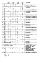
- Figure 3 is a truth table describing the actions taken by NIMs 20A and 20B upon the occurrence of certain conditions to minimize the consequences of such occurrences upon the operation of process control system 10.
- Row 1 describes the situation when both LCN 12 and UCN 14 are operating properly and neither primary NIM-A nor secondary NIM-B has a hardware or a software failure that prevents it from operating properly.
- NIM-B will transmit to NIM-A over bus 18 of UCN 14 a status message which includes data signifying that NIM-B's status is all right, as is that of LCN 12, and that NIM-B has received a status message from NIM-A over LCN bus 16.
- NIM-A Since NIM-A is unable to receive a status message from NIM-B over UCN bus 18 because drop cables 26A and 26B are severed, the failure of NIM-A to receive a status message from NIM-B or to communicate with any other module of UCN 14 for one second results in NIM-A recognizing that it has an UCN failure.
- NIM-A will transmit a redundancy message to NIM-B over LCN bus 16 at least once a second which message contains data informing NIM-B that NIM-A is isolated from UCN 14.
- NIM-B will transmit status messages to NIM-A over LCN bus 16 periodically at least once per second. After a 500 msec. delay, NIM-B listens to UCN bus 18 for a message from NIM-A.
- NIM-B sends a message to NIM-A over LCN bus 16 commanding NIM-A to terminate operations, and NIM-B takes over the functions of NIM-A. NIM-B will then transmit a message to universal station 32 concerning what has happened so that the operators of the process can take appropriate action to correct the problem, in this case, severed drop cables 26A and 26B.
- NIM-B is unable to communicate over UCN bus 18 because its drop cables 28A and 28B are severed, for example, NIM-B will attempt to transmit a status message over UCN bus 18.
- NIM-A since it did not receive a status message from NIM-B within the past second, does not send a status message to NIM-B over UCN bus 18.
- NIM-A will send a redundancy message to NIM-B over LCN bus 16 informing NIM-B that NIM-A did not receive a status message from NIM-B over bus 18 within the allotted time period, one second.
- NIM-B will then transmit a status message to NIM-A over LCN bus 16 containing data that NIM-B is unable to communicate with any modules of UCN 14.
- NIM-A after thirty attempts to receive a message from NIM-B over bus 18, NIM-A will send a message to NIM-B over LCN bus 16 for NIM-B to terminate its operations.
- NIM-B will in the mean time retry five times to send a status message to NIM-A over bus 18. If NIM-B does not receive a message from NIM-A over bus 18 of UCN 14 after five tries, NIM-B will terminate its operations. Thus, NIM-B under these circumstances is terminated by NIM-A or by its own decision.
- NIM-B will have received a status message from NIM-A over bus 18 of UCN that NIM-A is unable to communicate with any of the modules of LCN 12. NIM-B will then send a message to NIM-A over UCN bus 18 telling NIM-A to terminate operations since it is unable to communicate with LCN 12. Upon the receipt of such a message, NIM-A terminates operation and failover to NIM-B occurs. NIM-B will then notify module 32 of LCN 12 what has occurred.
- NIM-B Since NIM-B can not receive this message, NIM-B will after 1.7 seconds has elapsed, transmit three requests to NIM-A to the redundancy message over LCN bus 16. NIM-B waits for another 0.8 seconds and if NIM-B does not receive the requested message from NIM-A during that period, NIM-B concludes that it can not communicate with modules on LCN 12 Since NIM-B has received a status message from NIM-A that NIM-A can communicate with the modules of LCN 12, NIM-B terminates its operations. NIM-A then notifies universal station module 32 of LCN 12 of the state of affairs.
- NIM-B will transmit a routine status message to NIM-A including the status of LCN 12 as perceived by NIM-B at least once a second over bus 18.
- NIM-A will transmit a routine status message to NIM-B including the status of LCN 12 as perceived by NIM-A over bus bus 18.
- Primary NIM 20A will send a normal redundancy message to secondary NIM 20B over LCN bus 16. While NIM-B can receive this redundancy message from NIM-A, it cannot transmit an appropriate status message to NIM-A over LCN bus 16. If primary NIM 20A does not receive a proper message from NIM-B over LCN bus 16 for 60 seconds, NIM-A will transmit a message to NIM-B over UCN bus 18 telling NIM-B to terminate its operations.
- Row 6 describes the action taken by secondary NIM-B if NIM-B is unable to communicate with modules of the LCN.
- the action taken by NIM-B is to terminate its operation even though NIM-A is unable to communicate properly with modules of UCN 14 and NIM-B can. If both of the NIMs 20A and 20B are unable to communicate with LCN 12, no action is taken, row 7. If primary NIM 20A suffers an LCN failure and secondary NIM 20B an UCN failure, primary NIM 20A fails over to secondary NIM 20B, the situation described in row 8. If both NIM-A and NIM-B have an UCN failure, then no action is taken, row 9.
- NIM-B is unable to communicate with modules on either LCN 12 and UCN 14, the situation described in row 10, NIM-B terminates operation.
- Row 11 describes the situation where NIM-A can communicate only with LCN 12 and NIM-A can not communicate with either the LCN 12 or the UCN 14. Under such circumstances NIM-B terminates its operations. If neither NIM-A nor NIM-B can communicate with with either LCN 12 or UCN 14, then nothing can be done, the situation described by row 12.
- the most probable cause of both NIMs being unable to communicate with the LCN network, row 7; with the UCN network, row 9; or with both networks, row 12; is that both NIMs have been manually disconnected from the communication cables of the indicated network, or networks. Therefore, the two NIMs wait to be manually reconnected to the communication cables of the LCN, or the UCN, or both, and then resume operations.
- Row 13 describes the situation that occurs when NIM-A cannot communicate with either LCN 12 or UCN 14 but NIM-B can communicate with LCN 12 but not UCN 14. If this happens, NIM-A will failover to NIM-B. If NIM-A can not communicate with either LCN 12 or UCN 14, but NIM-A can, then NIM-A will failover to NIM-B, row 14. If NIM-A has a hardware or software failure that causes it to crash, then NIM-A will failover to NIM-B, row 15. If NIM-B has a hardware or software failure that causes NIM-B to crash, NIM-A will stop trying to communicate with NIM-B, row 16.
- both NIM-A and NIM-B can communicate with some of the modules of LCN 12 but not with each other over bus 16.
- NIM-B will transmit the normal status message including the status of LCN 12 to NIM-A over UCN bus 17 at least once a second.
- NIM-A will transmit the usual status message including the status of LCN 12 to NIM-B over UCN bus 18 at least once a second.
- NIM-A will transmit the usual redundancy message including the internal status of NIM-A, the status of UCN 14 as perceived by NIM-A and any update data NIM-A has for NIM-B to NIM-B over LCN bus 16.
- NIM-B Since NIM-B is unable to receive this message because of the cable fault in communication cables 16A and 16B, NIM-B after 1.7 seconds has elapsed, transmits three requests to NIM-A over LCN bus 16 requesting NIM-A to re-send the redundancy message over LCN cables 16A and 16B. If NIM-B does not receive a redundancy message from NIM-A within 0.8 seconds after transmitting the third request for NIM-A to do so, and based on status messages from NIM-A received over UCN bus 18, NIM-B determines that NIM-A can communicate with at least some modules of LCN 12. NIM-B then terminates its operation. Row 17 of the truth table of Fig. 3 describes this situation.
- this invention provides an improved method by which redundant network interface modules interconnecting the communication buses of two local area networks can determine when the primary is to fail over to the secondary based on information exchanged between the modules over the media of the two networks.
Landscapes
- Engineering & Computer Science (AREA)
- Theoretical Computer Science (AREA)
- Quality & Reliability (AREA)
- Physics & Mathematics (AREA)
- General Engineering & Computer Science (AREA)
- General Physics & Mathematics (AREA)
- Computer Security & Cryptography (AREA)
- Computer Networks & Wireless Communication (AREA)
- Signal Processing (AREA)
- Small-Scale Networks (AREA)
- Hardware Redundancy (AREA)
- Detection And Prevention Of Errors In Transmission (AREA)
- Maintenance And Management Of Digital Transmission (AREA)
- Data Exchanges In Wide-Area Networks (AREA)
- Control By Computers (AREA)
Abstract
Description
- The following copending patent applications relate to the invention of the present application and are incorporated herein by reference:
- A. "Method for Control Data Base Tracking in a Redundant Processor" by P. McLaughlin et al, Serial No. 07/299,859, filed January 23, 1989; and
- B. "Apparatus for Providing a Universal Interface to a Process Control System" by A. J. Hahn et al, Serial NO. , filed .
- All of the foregoing are assigned to the same assignee.
- This invention is in the field of methods by which the primary and secondary network interface modules determine their respective status and that of the networks with which they communicate to determine when the primary module shall failover in deference to the secondary and in which the secondary module determines that the primary module has failed in order to assume the role of the primary module.
- Process control systems which include a hierarchy of local area networks (LAN)s have been developed. An example of such a system is described and claimed in U. Patent No. 4,607,256, which issued to Russel A. Henzel on August 18, 1986. Another such system is illustrated and described in the cross-referenced application entitled "Apparatus for Providing a Universal Interface to a Process Control System" the disclosure of which is incorporated by reference into this application.
- In such systems, network interface modules (NIM)s provide communication and data translation capabilities so that modules of the two networks interconnects by a NIM can communicate. The reliability and fault tolerance of process control systems are significantly increased by incorporating in each network a standby, backup, secondary, or redundant module for each of the operating modules of each network, particularly, the NIMs interconnecting the networks, as well as by providing redundant cables over which the modules of each network communicate. Because of the importance of the functions performed by NIMs, providing each NIM of a process control system with a secondary or back up has a high priority. However, there is a need for an improved method by which a primary NIM and secondary NIM of a redundant pair of NIMs in such a system communicate, and the information communicated so that both NIMs have the capability of knowing each others status and of determining, or of controlling, when the secondary NIM will take over the function of the primary NIM; or, stated another way, when the primary NIM will failover to the secondary NIM.
- The present invention provides a method for communicating the respective status of redundant network interface modules (NIM)s between the modules and for controlling failover between the (NIM)s, one of which is designated as the primary NIM and the other as the secondary NIM. The NIMs are connected between the communication media of two local area networks (LAN)s so that the primary NIM can provide communication and data translation between the networks as required so that modules of one network can communicate with modules on the other.The secondary NIM of the redundant pair is available to provide the functions of the primary whenever failure of the primary NIM or failover of the primary NIM to the secondary NIM occurs. The primary and secondary NIMs communicate with each other at regular time intervals over the communication buses of both networks. The information communicated is in the form of messages, more accurately status messages, which include the status of the networks interconnected by the NIMs as perceived by each. The status messages transmitted by each MIN to the other over the communication bus of the first network includes the status of the NIM transmitting the information, the status of the second network as perceived by the transmitting NIM, and other information or data as required. The status messages transmitted by each NIM to the other over the communication bus of the second network include the status of the NIM transmitting the information, the status of the first network as perceived by the transmitting NIM as well as other information, or data, as required.
- Communication of the NIMs with one of the networks, such as the first, will take priority over communication with the second for reasons explained later. Some examples of the conditions resulting in failover of the primary NIM to the secondary NIM are: the primary NIM crashes, or fails; the primary NIM is unable to communicate with the first network and the secondary can; the primary NIM is unable to communicate with the second network, but otherwise is functioning properly, and the secondary NIM can communicate with both the first and second networks and the secondary NIM is otherwise functioning properly. Failover of the primary NIM to the secondary NIM will not occur if the secondary NIM is unable to communicate with either the first or second network, or if the secondary NIM has an internal problem which prevents its proper operation, such as a hardware or software failure which has caused the secondary NIM to perform improperly, or to crash.
- It is therefore an object of this invention to provide an improved method by which redundant network interface modules interconnecting the communication buses of two local area networks determine when the primary NIM shall failover to the secondary NIM based on information exchanged between the two modules over the media of the two networks.
- It is another object of this invention to provide an improved method by which redundant network interface modules interconnecting the communication buses of two local area networks determine when the primary shall fail over to the secondary without requiring any dedicated redundancy hardware.
- It is still another object of this invention to provide an improved method for controlling failover of a primary network interface module to the secondary network interface module in a process control system.
- It is yet another object of this invention to provide an improved method for controlling failover of a primary network interface module to the secondary network module in a process control system within a predetermined period of time after the occurrence of a fault causing failover to prevent interrupting the process being controlled by the system.
- Other objects, features and advantages of the invention will be readily apparent from the following description of a preferred embodiment thereof, taken in conjunction with the accompanying drawings, although variations and modifications may be affected without departing from the spirit and scope of the novel concepts of the disclosure, and in which:
- Fig. 1 is a schematic block diagram of a process control system, the two local area networks of which are provided with redundant network interface modules which practice the method of this invention.
- Fig. 2 is a truth table of conditions that determine when failover of the primary NIM to the secondary NIM occurs, when the secondary NIM terminates operation, and when no action takes place.
- In Figure 1,
process control system 10 includes local control network (LCN) 12, only a portion of which is illustrated, and universal control network (UCN) 14. LCN 12 includes acommunication bus 16, which in the preferred embodiment comprises redundantcoaxial cables coaxial cables LCN 12 and UCN 14 is provided by redundant network interface modules (NIM)s 20, which includes a pair of NIMs, 20A and 20B, with only one of the NIMs, such asNIM 20A providing such function as well as a data translation function at a given period of time. Under such circumstances, NIM-A is designated as the primary and NIM-B 20B which has the same capabilities as NIM 20A, is designated as the secondary NIM since NIM-B is the backup for NIM-A 20A. NIM-A is directly connected to dualredundant cables redundant connectors cables connectors NIMs 20, in the preferred embodiment, are connected toredundant cables 18A and 18-B of UCN 14, bydrop cables 26A and 26B for NIM-A anddrop cables - The modules of LCN illustrated in Fig. 1 include a
history module 30, a universaloperator station module 32 and anapplication module 34. Universaloperator station module 32 is the work station for one or more plant operators and provides the interface between the plant operator, or operators, and the process or processes of a plant for which the operators are responsible and which processes they monitor and control through the facilities and information provided bycontrol system 10. For a more detailed description ofLCN 12 and ofmodules LCN 12 which are not illustrated, reference is made to the teaching of U.S. Patent 4,607,256. - UCN 14 is provided with process manager modules (PM)s 36, 38, 40, and 42. For a more complete description of the the structure and functions of
NIMs 20 andPM modules PM modules PM 36, and translate signals produced by a process modules such asPM 36 to analog or digital output signals compatible to such devices. - In the preferred embodiment, both LCN 12 and UCN 14 are token passing local area networks (LAN)s typically with each module having a secondary or backup module available to take over for the primary module of a redundant pair. For example in LCN 12
history module 30,universal station module 32 andapplication module 34 each would normally be provided with a back up module to provide redundancy. LCN 12 may be provided with additional modules of the same or different types as is well known but which are not illustrated. In UCN 14process modules - The primary function of
NIMs 20A and 20B is to provide communications betweenLCN 12 and UCN 14. The ability ofNIMs 20A and 20B, particularly primary NIM-A to communicate with the modules ofLCN 12 is a key criteria in determining when primary NIM-A fails over to its secondary NIM-B. The ability of theNIMs 20A and 20B to communicate withLCN 12, particularly withuniversal station module 32 is becausemodule 32 provides the operators of the process controlled byprocess control system 10 with a vantage point, or window, to observe, or monitor the process being controlled and howprocess control system 10 is functioning. More particularly,module 32 provides the operators with information identifying when and where faults occur in the communication media or modules of any of the networks with whichuniversal station module 32 can communicate. Whenever a fault occurs and wherever it occurs, the responsibility of the operators of the process being controlled bysystem 10 is to take appropriate steps the find and fix the fault as quickly as possible. - Since the communication media of both
LCN 12 and UCN 14 are redundant coaxial cables,a fault or faults limited to one of the two cables of either or both networks, will not normally interfere with communications betweenLCN 12 and UCN 14 because each network has the capability for detecting faults in their redundant communication cables and of switching from the faulty cable ot the redundant, or back up, cable. - In the normal operation of
plant control system 10 when all the modules and communication cables of both networks are functioning properly, i.e., without any faults and both the primary NIM-A and the secondary NIM-B are both functioning without fault and no faults are present in any of their drop cables 22, 24, 26, 28. Under such circumstances, secondary NIM-B will transmit a status message to primary NIM-A at least once a second over bus 18 of UCN. This status message includes NIM-B's status, i.e. has NIM-B detected that it has suffered a hardware failure or a software failure; has NIM-B received a status message from primary NIM-A within the past one second over communication bus 18 of UCN 14; and whether secondary NIM-B is receiving signals from other modules ofUCN 14. The receipt of such signals signifies that NIM-B can communicate with UCN 14 and that therefore UCN 14 is functioning properly as perceived by NIM-B. - NIM-A transmits at least once a second to NIM-B a status message which includes the hardware and software status of NIM-A; whether NIM-A has received a status message from NIM-B within the previous second over communication bus 18, and whether NIM-A is receiving messages from and transmitting messages to other modules of
LCN 12. - Primary NIM-A will transmit a similar status message to NIM-B over the LCN's
communication bus 16 except that this message from NIM-A will include information as to whether NIM-A has received a status message from NIM-B within the past one second overcommunication bus 16 ofLCN 12 and the status ofUCN 14 as perceived by NIM-A; namely, that NIM-A is communicating with other modules of UCN 14. In addition this status message may include data which NIM-B uses to update its data base so that the data base of NIM-B is substantially the same as that of primary NIM-A. This facilitates NIM-B's being able to assume the functions of NIM-A with a minimum of delay upon a failover. This message sent by NIM-A to NIM-B overbus 16 is sometimes referred to as a redundancy message. - NIM-B will transmit a status message to NIM-A over
communication bus 16 including NIM-B's status and that ofUCN 14 as perceived by NIM-B after receiving a predetermined number of redundancy messages from NIM-A overcommunication bus 16, such as twenty, or at least once every second. - The type of failures, or faults, that can result in NIM-A failing over to NIM-B are: if NIM-A suffers a hardware failure or a software failure; if NIM-B does not receive a status message from NIM-A over
buses 16 or 18 ofLCN 12 orUCN 14 for 2.5 seconds in the preferred embodiment; if NIM-A is unable to transmit a status message to NIM-B and receive a response from NIM-B overcommunication bus 16 ofLCN 12 within 60 seconds; and NIM-A is unable to communicate with any module ofUCN 14 for more than 12 seconds and NIM-B is able to so communicate. - NIM-B is deemed to have a failure if it has a hardware or software fault; if NIM-A does not receive at least one status message from NIM-B over either
communication bus 16 ofLCN 12 or communication bus 18 ofUCN 14 during the previous 60 seconds; or if NIM-B does not receive any status messages from NIM-A overbus 16 ofLCN 12 for a period of 2.5 seconds but can receive messages from NIM-A over communication bus 18 ofUCN 14. - Figure 3 is a truth table describing the actions taken by
NIMs 20A and 20B upon the occurrence of certain conditions to minimize the consequences of such occurrences upon the operation ofprocess control system 10.Row 1 describes the situation when bothLCN 12 andUCN 14 are operating properly and neither primary NIM-A nor secondary NIM-B has a hardware or a software failure that prevents it from operating properly. - The situation described in
row 2 is one in which primary NIM-A is unable to transmit or receive signals from the communication media 18 ofUCN 14. Such a situation can occur if both of itsdrop cables 26A and 26B have been severed, for example. This occurrence is detected in the following way. NIM-B will transmit to NIM-A over bus 18 of UCN 14 a status message which includes data signifying that NIM-B's status is all right, as is that ofLCN 12, and that NIM-B has received a status message from NIM-A overLCN bus 16. Since NIM-A is unable to receive a status message from NIM-B over UCN bus 18 becausedrop cables 26A and 26B are severed, the failure of NIM-A to receive a status message from NIM-B or to communicate with any other module ofUCN 14 for one second results in NIM-A recognizing that it has an UCN failure. NIM-A will transmit a redundancy message to NIM-B overLCN bus 16 at least once a second which message contains data informing NIM-B that NIM-A is isolated fromUCN 14. NIM-B will transmit status messages to NIM-A overLCN bus 16 periodically at least once per second. After a 500 msec. delay, NIM-B listens to UCN bus 18 for a message from NIM-A. After five such attempts, NIM-B sends a message to NIM-A overLCN bus 16 commanding NIM-A to terminate operations, and NIM-B takes over the functions of NIM-A. NIM-B will then transmit a message touniversal station 32 concerning what has happened so that the operators of the process can take appropriate action to correct the problem, in this case, severeddrop cables 26A and 26B. - The conditions described in
row 3 are similar to those ofrow 2 except that secondary NIM-B is unable to communicate over UCN bus 18 because itsdrop cables LCN bus 16 informing NIM-B that NIM-A did not receive a status message from NIM-B over bus 18 within the allotted time period, one second. NIM-B will then transmit a status message to NIM-A overLCN bus 16 containing data that NIM-B is unable to communicate with any modules ofUCN 14. NIM-A after thirty attempts to receive a message from NIM-B over bus 18, NIM-A will send a message to NIM-B overLCN bus 16 for NIM-B to terminate its operations. NIM-B will in the mean time retry five times to send a status message to NIM-A over bus 18. If NIM-B does not receive a message from NIM-A over bus 18 ofUCN 14 after five tries, NIM-B will terminate its operations. Thus, NIM-B under these circumstances is terminated by NIM-A or by its own decision. - The conditions described in
row 4 of Fig.3 arise if theconnectors 22Aconnectors LCN bus 16 is not received by NIM-B, NIM-B after 1.7 seconds have elapsed begins transmitting requests to NIM-A overLCN bus 16 for NIM-A to retransmit its redundancy message overbus 16. This request is repeated three times. If no response to its requests are received by NIM-B after 0.8 seconds after the third request was transmitted, NIM-B will have received a status message from NIM-A over bus 18 of UCN that NIM-A is unable to communicate with any of the modules ofLCN 12. NIM-B will then send a message to NIM-A over UCN bus 18 telling NIM-A to terminate operations since it is unable to communicate withLCN 12. Upon the receipt of such a message, NIM-A terminates operation and failover to NIM-B occurs. NIM-B will then notifymodule 32 ofLCN 12 what has occurred. - The circumstances described by
row 5 of Fig. 3 occur if the drop cables 24-A and 24-B of NIM-B are cut are severed. When NIM-B transmits its status ofLCN 12 to NIM-A over UCN bus 18, it will report that it is unable to communicate with any of the modules ofLCN 12. NIM-A will transmit its status message once a second to NIM-B over UCN bus 18 to the effect that in so far as NIM-A is concerned, it can communicate withLCN 12 but not with NIM-B. NIM-A will attempt to transmit its redundancy message to NIM-B overLCN bus 16. Since NIM-B can not receive this message, NIM-B will after 1.7 seconds has elapsed, transmit three requests to NIM-A to the redundancy message overLCN bus 16. NIM-B waits for another 0.8 seconds and if NIM-B does not receive the requested message from NIM-A during that period, NIM-B concludes that it can not communicate with modules onLCN 12 Since NIM-B has received a status message from NIM-A that NIM-A can communicate with the modules ofLCN 12, NIM-B terminates its operations. NIM-A then notifiesuniversal station module 32 ofLCN 12 of the state of affairs. - The situation described by
row 5, of Fig. 3 can also occur if NIM-B should suffer a transmitter failure which is not detected and therefore is not reported as a hardware failure. Under such circumstances, NIM-B will transmit a routine status message to NIM-A including the status ofLCN 12 as perceived by NIM-B at least once a second over bus 18. NIM-A will transmit a routine status message to NIM-B including the status ofLCN 12 as perceived by NIM-A over bus bus 18.Primary NIM 20A will send a normal redundancy message to secondary NIM 20B overLCN bus 16. While NIM-B can receive this redundancy message from NIM-A, it cannot transmit an appropriate status message to NIM-A overLCN bus 16. Ifprimary NIM 20A does not receive a proper message from NIM-B overLCN bus 16 for 60 seconds, NIM-A will transmit a message to NIM-B over UCN bus 18 telling NIM-B to terminate its operations. -
Row 6 describes the action taken by secondary NIM-B if NIM-B is unable to communicate with modules of the LCN. The action taken by NIM-B is to terminate its operation even though NIM-A is unable to communicate properly with modules ofUCN 14 and NIM-B can. If both of theNIMs 20A and 20B are unable to communicate withLCN 12, no action is taken,row 7. Ifprimary NIM 20A suffers an LCN failure and secondary NIM 20B an UCN failure,primary NIM 20A fails over to secondary NIM 20B, the situation described inrow 8. If both NIM-A and NIM-B have an UCN failure, then no action is taken,row 9. If NIM-B is unable to communicate with modules on eitherLCN 12 andUCN 14, the situation described inrow 10, NIM-B terminates operation.Row 11 describes the situation where NIM-A can communicate only withLCN 12 and NIM-A can not communicate with either theLCN 12 or theUCN 14. Under such circumstances NIM-B terminates its operations. If neither NIM-A nor NIM-B can communicate with with eitherLCN 12 orUCN 14, then nothing can be done, the situation described byrow 12. With respect to the situations described inrows row 7; with the UCN network,row 9; or with both networks,row 12; is that both NIMs have been manually disconnected from the communication cables of the indicated network, or networks. Therefore, the two NIMs wait to be manually reconnected to the communication cables of the LCN, or the UCN, or both, and then resume operations. -
Row 13 describes the situation that occurs when NIM-A cannot communicate with eitherLCN 12 orUCN 14 but NIM-B can communicate withLCN 12 but notUCN 14. If this happens, NIM-A will failover to NIM-B. If NIM-A can not communicate with eitherLCN 12 orUCN 14, but NIM-A can, then NIM-A will failover to NIM-B,row 14. If NIM-A has a hardware or software failure that causes it to crash, then NIM-A will failover to NIM-B,row 15. If NIM-B has a hardware or software failure that causes NIM-B to crash, NIM-A will stop trying to communicate with NIM-B,row 16. - If both
trunk cables LCN 12 are severed betweenNIM 20A and NIM 20B, both NIM-A and NIM-B can communicate with some of the modules ofLCN 12 but not with each other overbus 16. When this occurs, NIM-B will transmit the normal status message including the status ofLCN 12 to NIM-A overUCN bus 17 at least once a second. NIM-A will transmit the usual status message including the status ofLCN 12 to NIM-B over UCN bus 18 at least once a second. NIM-A will transmit the usual redundancy message including the internal status of NIM-A, the status ofUCN 14 as perceived by NIM-A and any update data NIM-A has for NIM-B to NIM-B overLCN bus 16. Since NIM-B is unable to receive this message because of the cable fault incommunication cables LCN bus 16 requesting NIM-A to re-send the redundancy message overLCN cables LCN 12. NIM-B then terminates its operation.Row 17 of the truth table of Fig. 3 describes this situation. - From the foregoing, it is believed to be obvious that this invention provides an improved method by which redundant network interface modules interconnecting the communication buses of two local area networks can determine when the primary is to fail over to the secondary based on information exchanged between the modules over the media of the two networks.
Claims (12)
- Claim 1. The method by which redundant network modules (NIM)s interconnecting the communication buses of a first and a second local area network communicate with one another over the communication buses of the two networks, the first NIM being designated as the primary and the second NIM being designated as the secondary, the secondary NIM taking over the function of the primary NIM on the occurrence of certain predetermined conditions; comprising the steps of:
the first and second NIMs communicating with each other at predetermined time intervals over the communication buses of both networks, each communication between the NIMs over the communication bus of the first network including the status of the second network as perceived by the NIM transmitting the message and each communication between the NIMs over the communication bus of the second network including the status of the first network as perceived by the NIM transmitting the message;
the primary NIM failing over to the secondary NIM when the primary NIM determines that it is unable to communicate with the first network and the secondary NIM determines that is able to communicate with the first network. - Claim 2. The method of Claim 1 further comprising the step of the secondary NIM terminating its operation if the secondary NIM is unable to communicate with the first network.
- Claim 3. The method of Claim 2 in which each communication between the NIMs includes current operating status of the NIM originating such a communication, and further comprising the step of the secondary NIM terminating its operation if the secondary NIM detects it has suffered a hardware or a software failure.
- Claim 4. The method of Claim 3 further comprising the step of the primary NIM failing over to the secondary NIM if the primary NIM detects it has suffered a hardware or a software failure.
- Claim 5. The method of Claim 4 in which the primary NIM fails over to the secondary NIM without communicating the fact that it has suffered a hardware or a software failure to the secondary NIM.
- Claim 6. The method of Claim 5 in which the predetermined time intervals are one second.
- Claim 7. The method of Claim 6 in which the first local area network is a token passing network.
- Claim 8. The method of Claim 7 in which the second local area network is a token passing network.
- Claim 9. In a process control system including an universal control network (UCN) and a local control network (LCN), each being a local area network (LAN) with each network including a plurality of modules, the modules of each network communicating with one another over a communication bus, a pair of network interface modules (NIM)s, one of said NIMs being designated as a primary and the other NIM being designated as a secondary, each of the NIMs being connected between the communication buses of the UCN and the LCN and functioning to provide communication and data translation between the UCN and the LCN, the primary NIM providing such function unless replaced by the secondary NIM, and the secondary NIM being available to provide this function instead of the primary NIM upon the occurrence of predetermined conditions; comprising the steps of:1, the secondary NIM transmitting to the primary NIM at least once during every first period of time over the UCN's communication bus a status message, the secondary NIM's status message including the current operating status of the secondary NIM and the status of the LCN as determined by the the secondary NIM;2, the primary NIM transmitting to the secondary NIM at least once during every first period of time over the UCN communication bus a status message, the primary NIM's status message including the current operating status of the primary NIM and the status of the LCN as determined by the the primary NIM;3, the primary NIM transmitting to the secondary NIM at least once during every first period of time over the LCN communication bus a status message, the primary NIM's status message including current operating status of the primary NIM, of the UCN as determined by the primary NIM, and updating data with which the secondary NIM updates the secondary NIM's data base so that the data base of the secondary NIM substantially matches the data base of the primary NIM;4, the secondary NIM transmitting to the primary NIM upon receiving a predetermined number of messages from the primary NIM in step 3 containing updating data or during every first period of time, which ever first occurs, over the LCN communication bus a status message, the secondary NIM's status message including the current operating status of the secondary NIM and the current operating status of the UCN as determined by the the secondary NIM;5, the primary NIM failing over to the secondary NIM if the primary NIM if it is unable to communicate with the LCN, and the secondary NIM is able to communicate with the LCN and status messages containing such data are received by both NIMs;6, the secondary NIM terminating its operations if it determines that it is unable to communicate with the LCN;7, the primary NIM terminating operation of the secondary NIM if the secondary NIM is unable to communicate with one of the LANs;8, the primary NIM terminating communications with the secondary NIM if the secondary NIM crashes; and9, the secondary NIM taking over the function of the primary NIM if the primary NIM crashes, if the primary NIM is commanded to shut down by a command from a universal control station module of the first network, or if the primary NIM is powered down;
- Claim 10. The method of Claim 9 in which the first period of time is one second.
- Claim 11. The method of Claim 10 in which the universal control network is a token passing network.
- Claim 12. The method of Claim 11 in which the local control network is a token passing network.
Applications Claiming Priority (2)
| Application Number | Priority Date | Filing Date | Title |
|---|---|---|---|
| US404748 | 1989-09-08 | ||
| US07/404,748 US5016244A (en) | 1989-09-08 | 1989-09-08 | Method for controlling failover between redundant network interface modules |
Publications (3)
| Publication Number | Publication Date |
|---|---|
| EP0416943A2 true EP0416943A2 (en) | 1991-03-13 |
| EP0416943A3 EP0416943A3 (en) | 1992-07-15 |
| EP0416943B1 EP0416943B1 (en) | 1995-08-09 |
Family
ID=23600867
Family Applications (1)
| Application Number | Title | Priority Date | Filing Date |
|---|---|---|---|
| EP90309829A Expired - Lifetime EP0416943B1 (en) | 1989-09-08 | 1990-09-07 | Method for controlling failover between redundant network interface modules |
Country Status (6)
| Country | Link |
|---|---|
| US (1) | US5016244A (en) |
| EP (1) | EP0416943B1 (en) |
| JP (1) | JPH0666783B2 (en) |
| AU (1) | AU638047B2 (en) |
| CA (1) | CA2024744C (en) |
| DE (1) | DE69021469T2 (en) |
Cited By (11)
| Publication number | Priority date | Publication date | Assignee | Title |
|---|---|---|---|---|
| EP0649092A1 (en) * | 1993-10-15 | 1995-04-19 | Tandem Computers Incorporated | Method and apparatus for fault tolerant connection of a computing system to local area networks |
| EP0688121A1 (en) * | 1994-06-15 | 1995-12-20 | T.R.T. Telecommunications Radioelectriques Et Telephoniques | System for interconnection of local area networks and apparatus for use in such a system |
| EP0720337A2 (en) * | 1994-12-15 | 1996-07-03 | ABBPATENT GmbH | Method for highly reliable and consistent message communication |
| EP0770942A3 (en) * | 1995-10-27 | 1998-09-02 | Elan Schaltelemente GmbH | Arrangement to record and/or process signals from electrical components which fulfil technical security purposes or conditions for the apparatus of the installation |
| EP0902576A1 (en) * | 1997-08-27 | 1999-03-17 | DSC Telecom L.P. | Multiple network configuration with local and remote network redundancy by dual media redirect |
| EP1150461A1 (en) * | 2000-04-28 | 2001-10-31 | Airsys ATM S.A. | Redundant device of management of inputs/outputs, in particular a routing system |
| DE10152339B4 (en) * | 2001-09-14 | 2005-03-17 | Siemens Ag | Method and communication device for implementing at least one fail-safe communication relationship by a communication device arranged in a communication network |
| EP1592173A2 (en) | 2004-04-29 | 2005-11-02 | Alcatel | Protection switching methods and systems for electronic devices |
| EP2228724A1 (en) * | 2009-03-13 | 2010-09-15 | Giga-Byte Technology Co., Ltd. | Motherboard with backup network circuit |
| WO2011082131A1 (en) * | 2009-12-31 | 2011-07-07 | Schneider Electric USA, Inc. | Method and system for implementing redundant network interface modules in a distributed i/o system |
| WO2014071574A1 (en) | 2012-11-07 | 2014-05-15 | Abb Technology Ltd | Module, system and method of switching modules |
Families Citing this family (125)
| Publication number | Priority date | Publication date | Assignee | Title |
|---|---|---|---|---|
| CA1338639C (en) * | 1989-09-26 | 1996-10-08 | Seiichi Kubo | Communication control device |
| EP0444315B1 (en) * | 1990-02-26 | 1997-10-01 | Digital Equipment Corporation | System and method for software application event collection |
| US5291511A (en) * | 1990-04-16 | 1994-03-01 | Motorola, Inc. | Communication system network having self address information |
| DE69129856T2 (en) * | 1990-08-31 | 1999-03-18 | Bell Communications Research, Inc., Livingston, N.J. | SELF-HEALING, LOGICAL RING STRUCTURES USING, MESH NETWORK |
| US5218604A (en) * | 1990-08-31 | 1993-06-08 | Bell Communications Research, Inc. | Dual-hubbed arrangement to provide a protected ring interconnection |
| US5774640A (en) * | 1991-10-21 | 1998-06-30 | Tandem Computers Incorporated | Method and apparatus for providing a fault tolerant network interface controller |
| US5323394A (en) * | 1992-04-07 | 1994-06-21 | Digital Equipment Corporation | Selecting optimal routes in source routing bridging without exponential flooding of explorer packets |
| US5398242A (en) * | 1992-04-07 | 1995-03-14 | Digital Equipment Corporation | Automatically configuring LAN numbers |
| US5400333A (en) * | 1992-04-07 | 1995-03-21 | Digital Equipment Corporation | Detecting LAN number misconfiguration |
| US5844902A (en) * | 1992-04-07 | 1998-12-01 | Cabletron Systems, Inc. | Assigning multiple parallel bridge numbers to bridges |
| US5327424A (en) * | 1992-04-07 | 1994-07-05 | Digital Equipment Corporation | Automatically configuring parallel bridge numbers |
| JPH066362A (en) * | 1992-06-23 | 1994-01-14 | Hitachi Ltd | Message processing load distribution system for host system in lan |
| JP3281043B2 (en) * | 1992-08-06 | 2002-05-13 | マツダ株式会社 | Multiplex transmission equipment |
| US5781715A (en) * | 1992-10-13 | 1998-07-14 | International Business Machines Corporation | Fault-tolerant bridge/router with a distributed switch-over mechanism |
| US5426774A (en) * | 1993-04-06 | 1995-06-20 | Honeywell Inc. | Method for maintaining a sequence of events function during failover in a redundant multiple layer system |
| US5365512A (en) * | 1993-07-02 | 1994-11-15 | Ericsson Ge Mobile Communications Inc. | Multisite trunked RF communication system with reliable control messaging network |
| JPH0758717A (en) * | 1993-08-18 | 1995-03-03 | Fujitsu Ltd | Tributary interface of digital transmission equipment |
| US5473599A (en) * | 1994-04-22 | 1995-12-05 | Cisco Systems, Incorporated | Standby router protocol |
| US5491792A (en) * | 1994-09-23 | 1996-02-13 | Forney International, Inc. | Sequence of events system using a redundant analog I/O board system |
| US5737526A (en) * | 1994-12-30 | 1998-04-07 | Cisco Systems | Network having at least two routers, each having conditional filter so one of two transmits given frame and each transmits different frames, providing connection to a subnetwork |
| JP3628777B2 (en) | 1995-10-30 | 2005-03-16 | 株式会社日立製作所 | External storage device |
| US5790518A (en) * | 1995-12-22 | 1998-08-04 | Hughes Electronics Corporation | 1-for-N redundancy implementation on midplane |
| US6567410B1 (en) | 1996-08-08 | 2003-05-20 | Enterasys Networks, Inc. | Assigning multiple parallel bridge numbers to bridges having three or more ports |
| US5875290A (en) * | 1997-03-27 | 1999-02-23 | International Business Machines Corporation | Method and program product for synchronizing operator initiated commands with a failover process in a distributed processing system |
| US6108300A (en) * | 1997-05-02 | 2000-08-22 | Cisco Technology, Inc | Method and apparatus for transparently providing a failover network device |
| US6058182A (en) * | 1997-11-07 | 2000-05-02 | At&T Corporation | Communications switch permitting transparent maintenance of switch control system |
| JP3651742B2 (en) * | 1998-01-21 | 2005-05-25 | 株式会社東芝 | Plant monitoring system |
| US6195705B1 (en) | 1998-06-30 | 2001-02-27 | Cisco Technology, Inc. | Mobile IP mobility agent standby protocol |
| US6760444B1 (en) * | 1999-01-08 | 2004-07-06 | Cisco Technology, Inc. | Mobile IP authentication |
| US7149229B1 (en) * | 1999-01-08 | 2006-12-12 | Cisco Technology, Inc. | Mobile IP accounting |
| US6501746B1 (en) | 1999-01-08 | 2002-12-31 | Cisco Technology, Inc. | Mobile IP dynamic home address resolution |
| US7421077B2 (en) * | 1999-01-08 | 2008-09-02 | Cisco Technology, Inc. | Mobile IP authentication |
| US6636498B1 (en) | 1999-01-08 | 2003-10-21 | Cisco Technology, Inc. | Mobile IP mobile router |
| US6693874B1 (en) * | 1999-05-26 | 2004-02-17 | Siemens Information & Communication Networks, Inc. | System and method for enabling fault tolerant H.323 systems |
| US6621810B1 (en) | 1999-05-27 | 2003-09-16 | Cisco Technology, Inc. | Mobile IP intra-agent mobility |
| US7535871B1 (en) | 1999-05-27 | 2009-05-19 | Cisco Technology, Inc. | Mobile IP intra-agent mobility |
| US6434703B1 (en) | 1999-06-08 | 2002-08-13 | Cisco Technology, Inc. | Event initiation bus and associated fault protection for a telecommunications device |
| US6425009B1 (en) * | 1999-06-08 | 2002-07-23 | Cisco Technology, Inc. | Monitoring redundant control buses to provide a high availability local area network for a telecommunications device |
| US6550016B1 (en) * | 1999-06-08 | 2003-04-15 | Cisco Technology, Inc. | Protection bus and method for a telecommunications device |
| US6466964B1 (en) | 1999-06-15 | 2002-10-15 | Cisco Technology, Inc. | Methods and apparatus for providing mobility of a node that does not support mobility |
| US6751191B1 (en) | 1999-06-29 | 2004-06-15 | Cisco Technology, Inc. | Load sharing and redundancy scheme |
| WO2001022911A1 (en) | 1999-09-30 | 2001-04-05 | Waltco Truck Equipment Co. | Side door lifting apparatus |
| US6839829B1 (en) | 2000-01-18 | 2005-01-04 | Cisco Technology, Inc. | Routing protocol based redundancy design for shared-access networks |
| US7058007B1 (en) | 2000-01-18 | 2006-06-06 | Cisco Technology, Inc. | Method for a cable modem to rapidly switch to a backup CMTS |
| JP4462697B2 (en) | 2000-01-31 | 2010-05-12 | 株式会社日立製作所 | Storage controller |
| US7130629B1 (en) | 2000-03-08 | 2006-10-31 | Cisco Technology, Inc. | Enabling services for multiple sessions using a single mobile node |
| US6885633B1 (en) * | 2000-04-10 | 2005-04-26 | Stonesoft Oy | Network node and a system |
| US7280529B1 (en) * | 2000-05-20 | 2007-10-09 | Ciena Corporation | Providing network management access through user profiles |
| US6765892B1 (en) | 2000-06-26 | 2004-07-20 | Cisco Technology, Inc. | Optimizing IP multicast data transmission in a mobile IP environment |
| US6963918B1 (en) | 2000-06-29 | 2005-11-08 | Cisco Technology, Inc. | Voice over IP optimization for mobile IP |
| US6982967B1 (en) | 2000-06-29 | 2006-01-03 | Cisco Technology, Inc. | Methods and apparatus for implementing a proxy mobile node in a wireless local area network |
| US6625747B1 (en) | 2000-06-30 | 2003-09-23 | Dell Products L.P. | Computer storage system and failover method |
| US7042864B1 (en) | 2000-08-01 | 2006-05-09 | Cisco Technology, Inc. | Enabling push technologies for mobile IP |
| US7042876B1 (en) | 2000-09-12 | 2006-05-09 | Cisco Technology, Inc. | Stateful network address translation protocol implemented over a data network |
| US6959341B1 (en) | 2000-12-20 | 2005-10-25 | Cisco Technology, Inc. | Dynamic network allocation for mobile router |
| US6885667B1 (en) | 2000-12-26 | 2005-04-26 | Cisco Technology, Inc. | Redirection to a virtual router |
| US7295551B1 (en) * | 2000-12-28 | 2007-11-13 | Cisco Technology, Inc. | Support mobile device in asymmetric link environment |
| US7152238B1 (en) | 2000-12-29 | 2006-12-19 | Cisco Technology, Inc. | Enabling mobility for point to point protocol (PPP) users using a node that does not support mobility |
| US7051109B1 (en) * | 2001-02-21 | 2006-05-23 | Cisco Technology, Inc. | Methods and apparatus for using SCTP to provide mobility of a network device |
| US7881208B1 (en) | 2001-06-18 | 2011-02-01 | Cisco Technology, Inc. | Gateway load balancing protocol |
| US6654241B2 (en) * | 2001-06-29 | 2003-11-25 | Intel Corporation | High availability small foot-print server |
| DE50209248D1 (en) * | 2001-09-14 | 2007-02-22 | Siemens Ag | Method and communication device for implementing at least one fail-safe communication relationship |
| US7036143B1 (en) | 2001-09-19 | 2006-04-25 | Cisco Technology, Inc. | Methods and apparatus for virtual private network based mobility |
| US7227863B1 (en) | 2001-11-09 | 2007-06-05 | Cisco Technology, Inc. | Methods and apparatus for implementing home agent redundancy |
| US7409549B1 (en) | 2001-12-11 | 2008-08-05 | Cisco Technology, Inc. | Methods and apparatus for dynamic home agent assignment in mobile IP |
| US7227838B1 (en) | 2001-12-14 | 2007-06-05 | Cisco Technology, Inc. | Enhanced internal router redundancy |
| US7116634B1 (en) | 2001-12-21 | 2006-10-03 | Cisco Technology, Inc. | TCP sequence number recovery in a redundant forwarding system |
| US7079520B2 (en) * | 2001-12-28 | 2006-07-18 | Cisco Technology, Inc. | Methods and apparatus for implementing NAT traversal in mobile IP |
| US6922793B2 (en) * | 2002-02-14 | 2005-07-26 | Accton Technology Corporation | Method for recovering from malfunctions in an agent module of a modular network device |
| US7471661B1 (en) * | 2002-02-20 | 2008-12-30 | Cisco Technology, Inc. | Methods and apparatus for supporting proxy mobile IP registration in a wireless local area network |
| US7284057B2 (en) * | 2002-02-27 | 2007-10-16 | Cisco Technology, Inc. | Methods and apparatus for Mobile IP Home Agent clustering |
| US7587498B2 (en) * | 2002-05-06 | 2009-09-08 | Cisco Technology, Inc. | Methods and apparatus for mobile IP dynamic home agent allocation |
| US7346053B1 (en) | 2002-05-07 | 2008-03-18 | Cisco Technology, Inc. | Methods and apparatus for supporting IP multicast for a mobile router |
| US7599370B1 (en) | 2002-05-07 | 2009-10-06 | Cisco Technology, Inc. | Methods and apparatus for optimizing NAT traversal in Mobile IP |
| US7280557B1 (en) | 2002-06-28 | 2007-10-09 | Cisco Technology, Inc. | Mechanisms for providing stateful NAT support in redundant and asymetric routing environments |
| US7174376B1 (en) | 2002-06-28 | 2007-02-06 | Cisco Technology, Inc. | IP subnet sharing technique implemented without using bridging or routing protocols |
| US7379433B1 (en) | 2002-09-25 | 2008-05-27 | Cisco Technology, Inc. | Methods and apparatus for broadcast optimization in mobile IP |
| US7707310B2 (en) * | 2002-11-20 | 2010-04-27 | Cisco Technology, Inc. | Mobile IP registration supporting port identification |
| US7475241B2 (en) * | 2002-11-22 | 2009-01-06 | Cisco Technology, Inc. | Methods and apparatus for dynamic session key generation and rekeying in mobile IP |
| US7457289B2 (en) * | 2002-12-16 | 2008-11-25 | Cisco Technology, Inc. | Inter-proxy communication protocol for mobile IP |
| US7870389B1 (en) | 2002-12-24 | 2011-01-11 | Cisco Technology, Inc. | Methods and apparatus for authenticating mobility entities using kerberos |
| US7469282B2 (en) | 2003-01-21 | 2008-12-23 | At&T Intellectual Property I, L.P. | Method and system for provisioning and maintaining a circuit in a data network |
| US7362742B1 (en) | 2003-01-28 | 2008-04-22 | Cisco Technology, Inc. | Methods and apparatus for synchronizing subnet mapping tables |
| US7505432B2 (en) * | 2003-04-28 | 2009-03-17 | Cisco Technology, Inc. | Methods and apparatus for securing proxy Mobile IP |
| US7457234B1 (en) | 2003-05-14 | 2008-11-25 | Adtran, Inc. | System and method for protecting communication between a central office and a remote premises |
| US7194655B2 (en) * | 2003-06-12 | 2007-03-20 | International Business Machines Corporation | Method and system for autonomously rebuilding a failed server and a computer system utilizing the same |
| US7593346B2 (en) * | 2003-07-31 | 2009-09-22 | Cisco Technology, Inc. | Distributing and balancing traffic flow in a virtual gateway |
| US7417961B2 (en) * | 2003-12-09 | 2008-08-26 | Cisco Technology, Inc. | Methods and apparatus for implementing a speed sensitive mobile router |
| US7639623B2 (en) * | 2003-12-23 | 2009-12-29 | At&T Intellectual Property I, L.P. | Method and system for real time simultaneous monitoring of logical circuits in a data network |
| US7639606B2 (en) * | 2003-12-23 | 2009-12-29 | At&T Intellectual Property I, L.P. | Method and system for automatically rerouting logical circuit data in a virtual private network |
| US8199638B2 (en) | 2003-12-23 | 2012-06-12 | At&T Intellectual Property I, L.P. | Method and system for automatically rerouting logical circuit data in a data network |
| US8223632B2 (en) | 2003-12-23 | 2012-07-17 | At&T Intellectual Property I, L.P. | Method and system for prioritized rerouting of logical circuit data in a data network |
| US7646707B2 (en) * | 2003-12-23 | 2010-01-12 | At&T Intellectual Property I, L.P. | Method and system for automatically renaming logical circuit identifiers for rerouted logical circuits in a data network |
| US7609623B2 (en) * | 2003-12-23 | 2009-10-27 | At&T Intellectual Property I, L.P. | Method and system for automatically rerouting data from an overbalanced logical circuit in a data network |
| US8203933B2 (en) | 2003-12-23 | 2012-06-19 | At&T Intellectual Property I, L.P. | Method and system for automatically identifying a logical circuit failure in a data network |
| US7630302B2 (en) * | 2003-12-23 | 2009-12-08 | At&T Intellectual Property I, L.P. | Method and system for providing a failover circuit for rerouting logical circuit data in a data network |
| US7350099B2 (en) * | 2003-12-23 | 2008-03-25 | At&T Bls Intellectual Property, Inc. | Method and system for utilizing a logical failover circuit for rerouting data between data networks |
| US8339988B2 (en) * | 2004-04-22 | 2012-12-25 | At&T Intellectual Property I, L.P. | Method and system for provisioning logical circuits for intermittent use in a data network |
| US7768904B2 (en) * | 2004-04-22 | 2010-08-03 | At&T Intellectual Property I, L.P. | Method and system for fail-safe renaming of logical circuit identifiers for rerouted logical circuits in a data network |
| US7460468B2 (en) | 2004-04-22 | 2008-12-02 | At&T Intellectual Property I, L.P. | Method and system for automatically tracking the rerouting of logical circuit data in a data network |
| US7275192B2 (en) * | 2004-04-22 | 2007-09-25 | At&T Bls Intellectual Property, Inc. | Method and system for on demand selective rerouting of logical circuit data in a data network |
| US7466646B2 (en) * | 2004-04-22 | 2008-12-16 | At&T Intellectual Property I, L.P. | Method and system for automatically rerouting logical circuit data from a logical circuit failure to dedicated backup circuit in a data network |
| US7840988B1 (en) | 2004-05-07 | 2010-11-23 | Cisco Technology, Inc. | Front-end structure for access network line card |
| US7512830B2 (en) * | 2004-05-14 | 2009-03-31 | International Business Machines Corporation | Management module failover across multiple blade center chassis |
| US7447188B1 (en) | 2004-06-22 | 2008-11-04 | Cisco Technology, Inc. | Methods and apparatus for supporting mobile IP proxy registration in a system implementing mulitple VLANs |
| US7530091B2 (en) * | 2004-07-19 | 2009-05-05 | Pct International, Inc. | VOIP drop amplifier |
| US7639802B2 (en) * | 2004-09-27 | 2009-12-29 | Cisco Technology, Inc. | Methods and apparatus for bootstrapping Mobile-Foreign and Foreign-Home authentication keys in Mobile IP |
| US7502331B2 (en) * | 2004-11-17 | 2009-03-10 | Cisco Technology, Inc. | Infrastructure-less bootstrapping: trustless bootstrapping to enable mobility for mobile devices |
| US8059661B2 (en) * | 2004-12-29 | 2011-11-15 | Cisco Technology, Inc. | Methods and apparatus for using DHCP for home address management of nodes attached to an edge device and for performing mobility and address management as a proxy home agent |
| US7912431B2 (en) * | 2005-03-10 | 2011-03-22 | Commscope, Inc. Of North Carolina | Signal amplifiers having non-interruptible communication paths |
| US20100117728A1 (en) * | 2005-03-10 | 2010-05-13 | Robert Ryan Riggsby | Signal Amplifiers Having Communications Paths that Automatically Terminate to a Matched Termination in Response to a Power Interruption and Related Methods |
| US7626963B2 (en) * | 2005-10-25 | 2009-12-01 | Cisco Technology, Inc. | EAP/SIM authentication for mobile IP to leverage GSM/SIM authentication infrastructure |
| US7903585B2 (en) | 2006-02-15 | 2011-03-08 | Cisco Technology, Inc. | Topology discovery of a private network |
| US7633917B2 (en) * | 2006-03-10 | 2009-12-15 | Cisco Technology, Inc. | Mobile network device multi-link optimizations |
| US8295162B2 (en) | 2006-05-16 | 2012-10-23 | At&T Intellectual Property I, L.P. | System and method to achieve sub-second routing performance |
| US8085790B2 (en) * | 2006-07-14 | 2011-12-27 | Cisco Technology, Inc. | Ethernet layer 2 protocol packet switching |
| US8769597B2 (en) * | 2008-06-23 | 2014-07-01 | Pct International, Inc. | Amplifier with noise reduction |
| US20090320085A1 (en) | 2008-06-23 | 2009-12-24 | Jon-En Wang | House amplifier with return path gating |
| US8107360B2 (en) * | 2009-03-23 | 2012-01-31 | International Business Machines Corporation | Dynamic addition of redundant network in distributed system communications |
| WO2013165995A1 (en) * | 2012-04-30 | 2013-11-07 | Thermo King Corporation | Transport refrigeration system controller to engine control unit interface |
| US9699516B2 (en) | 2014-01-21 | 2017-07-04 | Commscope, Inc. Of North Carolina | Signal amplifiers that support MoCA communications at both active and passive output ports |
| JP2016035610A (en) * | 2014-08-01 | 2016-03-17 | 日本電気株式会社 | Information processing system, information processing apparatus, redundancy method, and program |
| US9727428B2 (en) | 2015-11-30 | 2017-08-08 | Red Hat Israel, Ltd. | Reverse network address translation failover |
| US10503617B2 (en) | 2017-02-16 | 2019-12-10 | Honeywell International Inc. | Method for synchronizing redundant controllers without hardware support |
| EP4063974A1 (en) * | 2021-03-23 | 2022-09-28 | ABB Schweiz AG | Controlling an industrial process using virtualized instances of control software |
Citations (2)
| Publication number | Priority date | Publication date | Assignee | Title |
|---|---|---|---|---|
| US4607256A (en) * | 1983-10-07 | 1986-08-19 | Honeywell, Inc. | Plant management system |
| US4831617A (en) * | 1987-08-31 | 1989-05-16 | Fujitsu Limited | Data communication system having means for switching between main and stand-by apparatuses |
Family Cites Families (5)
| Publication number | Priority date | Publication date | Assignee | Title |
|---|---|---|---|---|
| US4304001A (en) * | 1980-01-24 | 1981-12-01 | Forney Engineering Company | Industrial control system with interconnected remotely located computer control units |
| US4596012A (en) * | 1983-05-25 | 1986-06-17 | Reed Lockwood W | Master controller succession system for bus control access for data-communications local area networks |
| US4845609A (en) * | 1986-07-25 | 1989-07-04 | Systech Corporation | Computer communications subsystem using an embedded token-passing network |
| US4847837A (en) * | 1986-11-07 | 1989-07-11 | The United States Of America As Represented By The Administrator Of The National Aeronautics And Space Administration | Local area network with fault-checking, priorities and redundant backup |
| US4797881A (en) * | 1987-03-12 | 1989-01-10 | Sytek, Inc. | Bridge system for connecting networks |
-
1989
- 1989-09-08 US US07/404,748 patent/US5016244A/en not_active Expired - Lifetime
-
1990
- 1990-08-27 AU AU61363/90A patent/AU638047B2/en not_active Ceased
- 1990-09-06 CA CA002024744A patent/CA2024744C/en not_active Expired - Fee Related
- 1990-09-07 EP EP90309829A patent/EP0416943B1/en not_active Expired - Lifetime
- 1990-09-07 DE DE69021469T patent/DE69021469T2/en not_active Expired - Fee Related
- 1990-09-10 JP JP2237293A patent/JPH0666783B2/en not_active Expired - Lifetime
Patent Citations (2)
| Publication number | Priority date | Publication date | Assignee | Title |
|---|---|---|---|---|
| US4607256A (en) * | 1983-10-07 | 1986-08-19 | Honeywell, Inc. | Plant management system |
| US4831617A (en) * | 1987-08-31 | 1989-05-16 | Fujitsu Limited | Data communication system having means for switching between main and stand-by apparatuses |
Non-Patent Citations (1)
| Title |
|---|
| COMPUTER NETWORKS & ISDN SYSTEMS vol. 13, no. 4-5, 1987, AMSTERDAM, NETHERLANDS pages 323 - 332; N. LINGE ET AL: 'A Bridge Protocol for Creating a Spanning Tree Topology within an IEEE 802 Extended LAN Environment' * |
Cited By (23)
| Publication number | Priority date | Publication date | Assignee | Title |
|---|---|---|---|---|
| EP0649092A1 (en) * | 1993-10-15 | 1995-04-19 | Tandem Computers Incorporated | Method and apparatus for fault tolerant connection of a computing system to local area networks |
| AU685497B2 (en) * | 1993-10-15 | 1998-01-22 | Tandem Computers Incorporated | Method and apparatus for fault tolerant connection of a computing system to local area networks |
| EP0688121A1 (en) * | 1994-06-15 | 1995-12-20 | T.R.T. Telecommunications Radioelectriques Et Telephoniques | System for interconnection of local area networks and apparatus for use in such a system |
| FR2721465A1 (en) * | 1994-06-15 | 1995-12-22 | Trt Telecom Radio Electr | Local area interconnection system and equipment for use in such a system. |
| EP0720337A2 (en) * | 1994-12-15 | 1996-07-03 | ABBPATENT GmbH | Method for highly reliable and consistent message communication |
| EP0720337A3 (en) * | 1994-12-15 | 1997-06-11 | Abb Patent Gmbh | Method for highly reliable and consistent message communication |
| EP0770942A3 (en) * | 1995-10-27 | 1998-09-02 | Elan Schaltelemente GmbH | Arrangement to record and/or process signals from electrical components which fulfil technical security purposes or conditions for the apparatus of the installation |
| US6324161B1 (en) | 1997-08-27 | 2001-11-27 | Alcatel Usa Sourcing, L.P. | Multiple network configuration with local and remote network redundancy by dual media redirect |
| EP0902576A1 (en) * | 1997-08-27 | 1999-03-17 | DSC Telecom L.P. | Multiple network configuration with local and remote network redundancy by dual media redirect |
| US7707281B2 (en) | 2000-04-28 | 2010-04-27 | Airsys Atm S.A. | Redundant input/output management device, notably for data routing |
| FR2808353A1 (en) * | 2000-04-28 | 2001-11-02 | Airsys Atm S A | REDUNDANT INPUT / OUTPUT MANAGEMENT DEVICE, IN PARTICULAR COMPUTER ROUTING |
| EP1150461A1 (en) * | 2000-04-28 | 2001-10-31 | Airsys ATM S.A. | Redundant device of management of inputs/outputs, in particular a routing system |
| DE10152339B4 (en) * | 2001-09-14 | 2005-03-17 | Siemens Ag | Method and communication device for implementing at least one fail-safe communication relationship by a communication device arranged in a communication network |
| EP1592173A3 (en) * | 2004-04-29 | 2009-04-01 | Alcatel Lucent | Protection switching methods and systems for electronic devices |
| EP1592173A2 (en) | 2004-04-29 | 2005-11-02 | Alcatel | Protection switching methods and systems for electronic devices |
| EP2228724A1 (en) * | 2009-03-13 | 2010-09-15 | Giga-Byte Technology Co., Ltd. | Motherboard with backup network circuit |
| WO2011082131A1 (en) * | 2009-12-31 | 2011-07-07 | Schneider Electric USA, Inc. | Method and system for implementing redundant network interface modules in a distributed i/o system |
| CN102804699A (en) * | 2009-12-31 | 2012-11-28 | 施耐德电器工业公司 | Method and system for implementing redundant network interface modules in a distributed I/O system |
| WO2014071574A1 (en) | 2012-11-07 | 2014-05-15 | Abb Technology Ltd | Module, system and method of switching modules |
| CN104813613A (en) * | 2012-11-07 | 2015-07-29 | Abb技术有限公司 | Module, system and method of switching modules |
| EP2918048A4 (en) * | 2012-11-07 | 2016-07-06 | Abb Technology Ltd | Module, system and method of switching modules |
| US9787532B2 (en) | 2012-11-07 | 2017-10-10 | Abb Schweiz Ag | Module, system and method of switching modules |
| CN104813613B (en) * | 2012-11-07 | 2018-09-18 | Abb瑞士股份有限公司 | module, system and module switching method |
Also Published As
| Publication number | Publication date |
|---|---|
| EP0416943A3 (en) | 1992-07-15 |
| CA2024744A1 (en) | 1991-03-09 |
| AU6136390A (en) | 1991-03-14 |
| EP0416943B1 (en) | 1995-08-09 |
| JPH03106144A (en) | 1991-05-02 |
| US5016244A (en) | 1991-05-14 |
| AU638047B2 (en) | 1993-06-17 |
| DE69021469D1 (en) | 1995-09-14 |
| JPH0666783B2 (en) | 1994-08-24 |
| DE69021469T2 (en) | 1996-03-07 |
| CA2024744C (en) | 2002-12-17 |
Similar Documents
| Publication | Publication Date | Title |
|---|---|---|
| EP0416943B1 (en) | Method for controlling failover between redundant network interface modules | |
| EP0570882B1 (en) | A distributed control methodology and mechanism for implementing automatic protection switching | |
| US5784547A (en) | Method for fault-tolerant communication under strictly real-time conditions | |
| US5379278A (en) | Method of automatic communications recovery | |
| US6385665B1 (en) | System and method for managing faults in a data transmission system | |
| JPH04217136A (en) | Data integrity assurance system | |
| US5329528A (en) | Duplex communication control device | |
| CN112034774A (en) | Hot redundancy control method | |
| JP2996501B2 (en) | Equipment control method and device | |
| JP2503816B2 (en) | Building remote monitoring system | |
| JPH05304528A (en) | Multiplex communication node | |
| JP3419979B2 (en) | Device state management method and data communication system | |
| JP3761331B2 (en) | Data transmission method between duplex system stations | |
| JPH1049450A (en) | Recovery system for abnormal time of remote monitor system | |
| JP3552149B2 (en) | Communication control device and communication control method | |
| JPH09160875A (en) | Multi-agent mutual back-up system | |
| KR100279827B1 (en) | Independent operation control method of remote access switch module | |
| JPH02294134A (en) | Loop network intermittent fault recovery system | |
| JPH0454747A (en) | Data transfer system | |
| JPH09162910A (en) | Multiplex communication equipment and its control method | |
| JPH05111194A (en) | Supervisory controller for power system | |
| JPH01177296A (en) | Remote supervisory and controlling system | |
| JPH10242889A (en) | Mutual supervisory method for duplicate system | |
| Hilmer et al. | A can-based architecture for highly reliable communication systems | |
| JP2000151490A (en) | Transmission burst reception monitor circuit |
Legal Events
| Date | Code | Title | Description |
|---|---|---|---|
| PUAI | Public reference made under article 153(3) epc to a published international application that has entered the european phase |
Free format text: ORIGINAL CODE: 0009012 |
|
| AK | Designated contracting states |
Kind code of ref document: A2 Designated state(s): BE DE FR GB IT NL |
|
| PUAL | Search report despatched |
Free format text: ORIGINAL CODE: 0009013 |
|
| AK | Designated contracting states |
Kind code of ref document: A3 Designated state(s): BE DE FR GB IT NL |
|
| 17P | Request for examination filed |
Effective date: 19930108 |
|
| 17Q | First examination report despatched |
Effective date: 19940325 |
|
| GRAA | (expected) grant |
Free format text: ORIGINAL CODE: 0009210 |
|
| ITF | It: translation for a ep patent filed | ||
| AK | Designated contracting states |
Kind code of ref document: B1 Designated state(s): BE DE FR GB IT NL |
|
| REF | Corresponds to: |
Ref document number: 69021469 Country of ref document: DE Date of ref document: 19950914 |
|
| ET | Fr: translation filed | ||
| PLBE | No opposition filed within time limit |
Free format text: ORIGINAL CODE: 0009261 |
|
| STAA | Information on the status of an ep patent application or granted ep patent |
Free format text: STATUS: NO OPPOSITION FILED WITHIN TIME LIMIT |
|
| 26N | No opposition filed | ||
| REG | Reference to a national code |
Ref country code: GB Ref legal event code: IF02 |
|
| PGFP | Annual fee paid to national office [announced via postgrant information from national office to epo] |
Ref country code: NL Payment date: 20040809 Year of fee payment: 15 |
|
| PGFP | Annual fee paid to national office [announced via postgrant information from national office to epo] |
Ref country code: GB Payment date: 20040812 Year of fee payment: 15 |
|
| PGFP | Annual fee paid to national office [announced via postgrant information from national office to epo] |
Ref country code: FR Payment date: 20040902 Year of fee payment: 15 |
|
| PGFP | Annual fee paid to national office [announced via postgrant information from national office to epo] |
Ref country code: BE Payment date: 20040928 Year of fee payment: 15 |
|
| PGFP | Annual fee paid to national office [announced via postgrant information from national office to epo] |
Ref country code: DE Payment date: 20040930 Year of fee payment: 15 |
|
| PG25 | Lapsed in a contracting state [announced via postgrant information from national office to epo] |
Ref country code: IT Free format text: LAPSE BECAUSE OF NON-PAYMENT OF DUE FEES;WARNING: LAPSES OF ITALIAN PATENTS WITH EFFECTIVE DATE BEFORE 2007 MAY HAVE OCCURRED AT ANY TIME BEFORE 2007. THE CORRECT EFFECTIVE DATE MAY BE DIFFERENT FROM THE ONE RECORDED. Effective date: 20050907 Ref country code: GB Free format text: LAPSE BECAUSE OF NON-PAYMENT OF DUE FEES Effective date: 20050907 |
|
| PG25 | Lapsed in a contracting state [announced via postgrant information from national office to epo] |
Ref country code: BE Free format text: LAPSE BECAUSE OF NON-PAYMENT OF DUE FEES Effective date: 20050930 |
|
| PG25 | Lapsed in a contracting state [announced via postgrant information from national office to epo] |
Ref country code: NL Free format text: LAPSE BECAUSE OF NON-PAYMENT OF DUE FEES Effective date: 20060401 Ref country code: DE Free format text: LAPSE BECAUSE OF NON-PAYMENT OF DUE FEES Effective date: 20060401 |
|
| GBPC | Gb: european patent ceased through non-payment of renewal fee |
Effective date: 20050907 |
|
| PG25 | Lapsed in a contracting state [announced via postgrant information from national office to epo] |
Ref country code: FR Free format text: LAPSE BECAUSE OF NON-PAYMENT OF DUE FEES Effective date: 20060531 |
|
| NLV4 | Nl: lapsed or anulled due to non-payment of the annual fee |
Effective date: 20060401 |
|
| REG | Reference to a national code |
Ref country code: FR Ref legal event code: ST Effective date: 20060531 |
|
| BERE | Be: lapsed |
Owner name: *HONEYWELL INC. Effective date: 20050930 |