EP0416779B1 - Pusher Mechanism for glass forming machine - Google Patents
Pusher Mechanism for glass forming machine Download PDFInfo
- Publication number
- EP0416779B1 EP0416779B1 EP90309242A EP90309242A EP0416779B1 EP 0416779 B1 EP0416779 B1 EP 0416779B1 EP 90309242 A EP90309242 A EP 90309242A EP 90309242 A EP90309242 A EP 90309242A EP 0416779 B1 EP0416779 B1 EP 0416779B1
- Authority
- EP
- European Patent Office
- Prior art keywords
- pusher mechanism
- container
- conduit means
- handling arm
- Prior art date
- Legal status (The legal status is an assumption and is not a legal conclusion. Google has not performed a legal analysis and makes no representation as to the accuracy of the status listed.)
- Expired - Lifetime
Links
- 230000007246 mechanism Effects 0.000 title claims description 19
- 238000007496 glass forming Methods 0.000 title claims description 4
- 239000011521 glass Substances 0.000 description 3
- 238000006073 displacement reaction Methods 0.000 description 1
- 238000004519 manufacturing process Methods 0.000 description 1
Images
Classifications
-
- C—CHEMISTRY; METALLURGY
- C03—GLASS; MINERAL OR SLAG WOOL
- C03B—MANUFACTURE, SHAPING, OR SUPPLEMENTARY PROCESSES
- C03B9/00—Blowing glass; Production of hollow glass articles
- C03B9/30—Details of blowing glass; Use of materials for the moulds
- C03B9/44—Means for discharging combined with glass-blowing machines, e.g. take-outs
- C03B9/453—Means for pushing newly formed glass articles onto a conveyor, e.g. sweep-out mechanisms; Dead-plate mechanisms
Definitions
- the present invention relates to machinery for manufacturing glass containers, and specifically, to pusher mechanisms which transfer glass containers deposited on a dead plate of an individual section machine to a moving conveyor which will deliver the containers to a Lehr.
- a pneumatic cylinder extends a container handling arm, having a plurality of L-shaped pockets, to a container receiving location. Formed containers are deposited proximate these pockets on a dead plate and in some such mechanisms air under pressure is directed toward the containers by a pocket air distributor secured to the dead plate opposite the container handling arm to blow the containers fully into their pockets (see e.g. FR-A-2 531 420).
- the present invention provides a pusher mechanism for transferring a selected number of containers from a dead plate of a glass forming machine to a conveyor
- a container handling arm including a corresponding number of pockets each having a container engaging corner means for displacing said container handling arm from a retracted position to an advanced, container receiving, position and for displacing said advanced container handling arm from said receiving position through an arc to a deposit position at which containers are transferred to the conveyor
- the pusher mechanism comprises conduit means displaceable with the container handling arm and associated with each pocket each conduit means being selectively aimed to direct air discharged therefrom toward the corner of the associated pocket, and means for supplying air under pressure to said conduit means when a container is in the corner of the associated pocket.
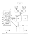
- a pusher mechanism for a multi-gob individual section glass forming machine operates to transfer a selected number of containers 10 (here three) deposited on a dead plate 12 to a conveyor 60.
- a container handling arm 14 Prior to placement of the containers on the dead plate 12, a container handling arm 14 which has correspondingly three U shaped pockets 16 each having a container engaging corner (there could be 1, 2, 3 or 4 such pockets) is moved to an advanced container receiving position from a retracted position.
- the arm 14 is secured to a rod 18 of a extend/retract pneumatic cylinder 20 which is extended to the container receiving position by connecting extend air having a selected pressure P1 to the cylinder to displace a piston 22, and hence, rod 18.
- Two-position selector switch S which is controlled by a machine controller 24 is set to one position connecting extend air P1 via extend air line 23 to the cylinder 20.
- this pressure which can be adjusted by changing the setting of a needle valve N is low (15 psi, for example) so that piston advance will be slow.
- the controller 24 switches the selector switch S to its second position connecting a second pressure source P2 (pocket air) to the extend line 23.
- This second pressure P2 is substantially higher (45 psi, for example) than extend air pressure and can also be adjusted via a second needle valve N.
- the pusher mechanism also comprises rotating means 21 which moves the container handling arm 14 from its container receiving position through an arc to a deposit position (shown in dotted lines in Figure 1) at which the containers are transferred to the conveyor 60.
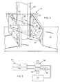
- a conduit 30 extends through the piston 22 and rod 18, and communicates via a conduit 31 with upper and lower air conduits 32 which are drilled into side walls 38 and rear walls 39 of the pockets 16. These conduits deliver air (either at extend pressure or pocket air pressure) to cylindrical openings 34 in the pocket side walls 38 which are aimed horizontally at the opposite corner of the pocket. Since these openings are small and the pressure is high, air will be discharged at a velocity high enough to locate the container fully in its pocket.
- the conduits 30, 31, 32 may be substantially larger in cross section than the cylindrical opening 34 to assure uniform pressure at these openings. Such locating of a container is assisted by the continuous surface of its U-shaped pocket. Pocket air will be turned on when the piston 22 is fully advanced and turned off before completion of swinging movement of the arm 14 through an arc to the deposit position to effect transfer of the containers to the conveyor 60.
- the pockets 16 of the handling arm 14 are staggered, that is to say rear walls 39 of the pockets are progressively stepped rather than in line as shown in Figure 1.
- the arrangement described above is particularly useful with a mechanism with such staggered pockets.
Landscapes
- Engineering & Computer Science (AREA)
- Chemical & Material Sciences (AREA)
- Manufacturing & Machinery (AREA)
- Materials Engineering (AREA)
- Organic Chemistry (AREA)
- Re-Forming, After-Treatment, Cutting And Transporting Of Glass Products (AREA)
- Special Conveying (AREA)
Description
- The present invention relates to machinery for manufacturing glass containers, and specifically, to pusher mechanisms which transfer glass containers deposited on a dead plate of an individual section machine to a moving conveyor which will deliver the containers to a Lehr.
- In known pusher mechanisms, a pneumatic cylinder extends a container handling arm, having a plurality of L-shaped pockets, to a container receiving location. Formed containers are deposited proximate these pockets on a dead plate and in some such mechanisms air under pressure is directed toward the containers by a pocket air distributor secured to the dead plate opposite the container handling arm to blow the containers fully into their pockets (see e.g. FR-A-2 531 420).
- It is an object of the present invention to provide a pusher mechanism in which the containers are rapidly located in their pockets and are maintained so located during rotational displacement of the pusher mechanism as it transfers the containers from the, dead plate to the conveyor.
- The present invention provides a pusher mechanism for transferring a selected number of containers from a dead plate of a glass forming machine to a conveyor comprising
a container handling arm including a corresponding number of pockets each having a container engaging corner
means for displacing said container handling arm from a retracted position to an advanced, container receiving, position and for displacing said advanced container handling arm from said receiving position through an arc to a deposit position at which containers are transferred to the conveyor
characterized in that the pusher mechanism comprises conduit means displaceable with the container handling arm and associated with each pocket each conduit means being selectively aimed to direct air discharged therefrom toward the corner of the associated pocket, and
means for supplying air under pressure to said conduit means when a container is in the corner of the associated pocket. - There now follows a description, to be read with reference to the accompanying drawings, of a preferred embodiment of the invention chosen to illustrate it by way of example.
- Referring to the drawings.
- Figure 1 is a schematic showing of a pusher mechanism;
- Figure 2 is an oblique view of a container receiving pocket illustrated in Figure 1;
and - Figure 3 is a schematic showing of an alternate arrangement for supplying air to a pusher mechanism.
- A pusher mechanism for a multi-gob individual section glass forming machine operates to transfer a selected number of containers 10 (here three) deposited on a
dead plate 12 to aconveyor 60. Prior to placement of the containers on thedead plate 12, acontainer handling arm 14 which has correspondingly three U shapedpockets 16 each having a container engaging corner (there could be 1, 2, 3 or 4 such pockets) is moved to an advanced container receiving position from a retracted position. Thearm 14 is secured to arod 18 of a extend/retractpneumatic cylinder 20 which is extended to the container receiving position by connecting extend air having a selected pressure P1 to the cylinder to displace apiston 22, and hence,rod 18. (Two-position selector switch S which is controlled by amachine controller 24 is set to one position connecting extend air P1 via extendair line 23 to the cylinder 20). Generally, this pressure, which can be adjusted by changing the setting of a needle valve N is low (15 psi, for example) so that piston advance will be slow. When thecontainer handling arm 14 is fully advanced, thecontroller 24 switches the selector switch S to its second position connecting a second pressure source P2 (pocket air) to theextend line 23. This second pressure P2 is substantially higher (45 psi, for example) than extend air pressure and can also be adjusted via a second needle valve N. - The pusher mechanism also comprises rotating means 21 which moves the
container handling arm 14 from its container receiving position through an arc to a deposit position (shown in dotted lines in Figure 1) at which the containers are transferred to theconveyor 60. - A
conduit 30 extends through thepiston 22 androd 18, and communicates via aconduit 31 with upper andlower air conduits 32 which are drilled intoside walls 38 andrear walls 39 of thepockets 16. These conduits deliver air (either at extend pressure or pocket air pressure) tocylindrical openings 34 in thepocket side walls 38 which are aimed horizontally at the opposite corner of the pocket. Since these openings are small and the pressure is high, air will be discharged at a velocity high enough to locate the container fully in its pocket. Theconduits cylindrical opening 34 to assure uniform pressure at these openings. Such locating of a container is assisted by the continuous surface of its U-shaped pocket. Pocket air will be turned on when thepiston 22 is fully advanced and turned off before completion of swinging movement of thearm 14 through an arc to the deposit position to effect transfer of the containers to theconveyor 60. - In an alternate arrangement (Figure 3), air under pressure supplied from a single source is distributed by a
distribution rack 50 havingconnections needle valve 56 to reduce the pressure as desired and the pocket air line additionally includes acheck valve 58 since it is open to exhaust when extend air is applied. - In many pusher mechanisms installed in glass machines the
pockets 16 of thehandling arm 14 are staggered, that is to sayrear walls 39 of the pockets are progressively stepped rather than in line as shown in Figure 1. The arrangement described above is particularly useful with a mechanism with such staggered pockets.
Claims (4)
- A pusher mechanism for transferring a selected number of containers (10) from a dead plate (12) of a glass forming machine to a conveyor (60) comprising
a container handling arm (14) including a corresponding number of pockets (16) each having a container engaging corner
means (P1,N,S,23,18,20,22;21) for displacing said container handling arm (14) from a retracted position to an advanced container receiving position and for displacing said advanced container handling arm from said receiving position through an arc to a deposit position at which containers are transferred to the conveyor
characterized in that the pusher mechanism comprises conduit means (30, 32, 34) displaceable with the container handling arm and associated with each pocket (16) each conduit means being selectively aimed to direct air discharged therefrom toward the corner of the associated pocket (16), and
means (P2,N,S,23) for supplying air under pressure to said conduit means when a container is in the corner of the associated pocket. - A pusher mechanism according to claim 1 characterized in that each of said conduit means (30,32,34) includes a pair of vertically spaced exit holes (34) through which the air is discharged.
- A pusher mechanism according to claim 2 characterised in that each pocket (16) comprises continuous U-shaped walls (38, 39) and the conduit means (30,32,34) includes conduits (32) defined within the walls.
- A pusher mechanism according to claim 3, wherein the displacing means (P1,N,S,23,18,20,22;21) comprises a cylinder (20) having a moveable piston (22) and rod (18) and the conduit means (30,32,34) comprises a hole (30) extending axially through said piston and rod.
Applications Claiming Priority (2)
| Application Number | Priority Date | Filing Date | Title |
|---|---|---|---|
| US07/402,956 US4927444A (en) | 1989-09-05 | 1989-09-05 | Pusher mechanism for glass forming machine |
| US402956 | 1989-09-05 |
Publications (2)
| Publication Number | Publication Date |
|---|---|
| EP0416779A1 EP0416779A1 (en) | 1991-03-13 |
| EP0416779B1 true EP0416779B1 (en) | 1993-12-08 |
Family
ID=23593959
Family Applications (1)
| Application Number | Title | Priority Date | Filing Date |
|---|---|---|---|
| EP90309242A Expired - Lifetime EP0416779B1 (en) | 1989-09-05 | 1990-08-23 | Pusher Mechanism for glass forming machine |
Country Status (4)
| Country | Link |
|---|---|
| US (1) | US4927444A (en) |
| EP (1) | EP0416779B1 (en) |
| JP (1) | JPH0397631A (en) |
| DE (1) | DE69005061T2 (en) |
Families Citing this family (19)
| Publication number | Priority date | Publication date | Assignee | Title |
|---|---|---|---|---|
| GB9023103D0 (en) * | 1990-10-24 | 1990-12-05 | Emhart Ind | Push out device for a glassware forming machine |
| US5037466A (en) * | 1991-02-06 | 1991-08-06 | Emhart Industries, Inc. | Pushout for I.S. machine |
| US5061309A (en) * | 1991-02-06 | 1991-10-29 | Emhart Industries, Inc. | Multiple row pusher system for glass forming machine |
| US5527372A (en) * | 1994-08-24 | 1996-06-18 | Emhart Glass Machinery Investments Inc. | Pusher mechanism for I.S. glass forming machine |
| FR2743792B1 (en) * | 1996-01-19 | 1998-03-13 | Saint Gobain Emballage | PROCESS AND DEVICE FOR HANDLING ARTICLES |
| DE19800080C1 (en) * | 1998-01-02 | 1999-03-18 | Heye Hermann Fa | Glass moulding machine with transfer units, and method for transferring glass articles |
| DE29902149U1 (en) | 1999-02-06 | 1999-08-05 | Fa. Hermann Heye, 31683 Obernkirchen | Device for pushing hollow glass objects onto a conveyor belt |
| US6269662B1 (en) * | 1999-03-05 | 2001-08-07 | Emhart Glass S.A. | Pneumatic machine control unit for an I.S. machine |
| DE19957079B4 (en) | 1999-11-26 | 2004-03-11 | Heye International Gmbh | Device for pushing glass objects |
| GB0030081D0 (en) * | 2000-12-09 | 2001-01-24 | Sheppee Internat Ltd | Fluid actuated piston |
| KR100385284B1 (en) * | 2001-07-11 | 2003-05-23 | 주식회사 럭스퍼트 | Optical powermeter |
| US6823696B2 (en) * | 2001-12-05 | 2004-11-30 | Emhart Glass S.A. | Glass container forming machine |
| GB2414721A (en) * | 2004-06-05 | 2005-12-07 | Lattimer Ltd | Pivoted pusher with pneumatic article retention/cooling means |
| ITTO20050713A1 (en) * | 2005-10-07 | 2007-04-08 | Bottero Spa | METHOD AND PUSHING DEVICE FOR THE TRANSFER OF GLASS ITEMS |
| US7320230B2 (en) * | 2005-11-07 | 2008-01-22 | Emhart Glass Sa | Pushout mechanism for I.S. machine |
| ITTO20060760A1 (en) * | 2006-10-20 | 2008-04-21 | Bottero Spa | PUSHING DEVICE FOR THE TRANSFER OF GLASS ITEMS |
| ITTO20060759A1 (en) * | 2006-10-20 | 2008-04-21 | Bottero Spa | PUSHING DEVICE FOR THE TRANSFER OF GLASS ITEMS |
| ITTO20070090A1 (en) | 2007-02-07 | 2008-08-08 | Bottero Spa | GROUP FOR OPENING / CLOSING MOLDS OF A MACHINE FOR FORMING GLASS ITEMS |
| ITTO20070495A1 (en) * | 2007-07-06 | 2009-01-07 | Bottero Spa | GROUP OF HANDLING AND COOLING OF A MOLD FOR A MACHINE FOR FORMING GLASS ITEMS |
Family Cites Families (4)
| Publication number | Priority date | Publication date | Assignee | Title |
|---|---|---|---|---|
| US3249201A (en) * | 1964-11-24 | 1966-05-03 | Emhart Corp | Apparatus for moving newly formed glassware articles of unstable configuration onto a conveyor |
| US4162911A (en) * | 1977-07-14 | 1979-07-31 | Owens-Illinois, Inc. | Plural glass forming machines with lehr conveyor |
| MX148331A (en) * | 1980-10-27 | 1983-04-11 | Invest Fic Fideicomiso | IMPROVEMENTS IN ELECTRONIC CONTROL FOR ARTICLE PULLER IN MACHINES FOR MANUFACTURING OF GLASS ARTICLES OR OTHER MATERIALS |
| US4462519A (en) * | 1982-08-03 | 1984-07-31 | Maul Technology Corporation | Glass container pusher |
-
1989
- 1989-09-05 US US07/402,956 patent/US4927444A/en not_active Expired - Fee Related
-
1990
- 1990-08-17 JP JP2217984A patent/JPH0397631A/en active Pending
- 1990-08-23 EP EP90309242A patent/EP0416779B1/en not_active Expired - Lifetime
- 1990-08-23 DE DE90309242T patent/DE69005061T2/en not_active Expired - Fee Related
Also Published As
| Publication number | Publication date |
|---|---|
| EP0416779A1 (en) | 1991-03-13 |
| DE69005061T2 (en) | 1994-05-11 |
| DE69005061D1 (en) | 1994-01-20 |
| JPH0397631A (en) | 1991-04-23 |
| US4927444A (en) | 1990-05-22 |
Similar Documents
| Publication | Publication Date | Title |
|---|---|---|
| EP0416779A1 (en) | Pusher Mechanism for glass forming machine | |
| US4680000A (en) | Apparatus for applying labels in the molds of a plastic blow molding machine | |
| US5632588A (en) | Automatic tool changer | |
| EP1318089B1 (en) | Conveying device for transfering batches of laminar articles standing on edge | |
| CA1098705A (en) | Multi-station glass-forming machine | |
| EP0603011B1 (en) | Glass container forming machine control | |
| GB2174667A (en) | Article-handling apparatus for transferring articles between conveyors | |
| GB2172257A (en) | Apparatus for introducing pieces of sweets into boxes or packaging inserts | |
| EP0180394B1 (en) | Control of apparatus for use in the manufacture of glassware articles | |
| US4162911A (en) | Plural glass forming machines with lehr conveyor | |
| US4409013A (en) | 90 Degree push-out for glassware forming machines and electronic control for the same | |
| GB2359077A (en) | Pushout mechanism for I.S. glass moulding machine | |
| JPS60112629A (en) | Glass former gob supply device | |
| GB2301338A (en) | A Handling System for Workpieces | |
| JPS6140614B2 (en) | ||
| JP4937432B2 (en) | I.S. Machine ejection mechanism | |
| US4244725A (en) | Glassware handling systems | |
| US4599759A (en) | Transfer apparatus | |
| JP4198797B2 (en) | Mold opening and closing mechanism for I.S. machines | |
| KR100518300B1 (en) | Transfer device for substantially round and brittle goods | |
| US4037731A (en) | Workpiece transport apparatus | |
| US6192285B1 (en) | Controller for work transfer system | |
| JPH09118432A (en) | Transferring method and device for bagged package | |
| US5311978A (en) | Loading apparatus | |
| JP4346709B2 (en) | I.S. Machinery |
Legal Events
| Date | Code | Title | Description |
|---|---|---|---|
| PUAI | Public reference made under article 153(3) epc to a published international application that has entered the european phase |
Free format text: ORIGINAL CODE: 0009012 |
|
| AK | Designated contracting states |
Kind code of ref document: A1 Designated state(s): DE FR GB IT |
|
| 17P | Request for examination filed |
Effective date: 19910819 |
|
| RAP1 | Party data changed (applicant data changed or rights of an application transferred) |
Owner name: EMHART GLASS MACHINERY INC., |
|
| RAP1 | Party data changed (applicant data changed or rights of an application transferred) |
Owner name: EMHART GLASS MACHINERY INVESTMENTS INC. |
|
| 17Q | First examination report despatched |
Effective date: 19930222 |
|
| GRAA | (expected) grant |
Free format text: ORIGINAL CODE: 0009210 |
|
| AK | Designated contracting states |
Kind code of ref document: B1 Designated state(s): DE FR GB IT |
|
| REF | Corresponds to: |
Ref document number: 69005061 Country of ref document: DE Date of ref document: 19940120 |
|
| ET | Fr: translation filed | ||
| ITF | It: translation for a ep patent filed | ||
| PLBE | No opposition filed within time limit |
Free format text: ORIGINAL CODE: 0009261 |
|
| STAA | Information on the status of an ep patent application or granted ep patent |
Free format text: STATUS: NO OPPOSITION FILED WITHIN TIME LIMIT |
|
| 26N | No opposition filed | ||
| PGFP | Annual fee paid to national office [announced via postgrant information from national office to epo] |
Ref country code: GB Payment date: 19970716 Year of fee payment: 8 |
|
| PGFP | Annual fee paid to national office [announced via postgrant information from national office to epo] |
Ref country code: FR Payment date: 19970721 Year of fee payment: 8 |
|
| PGFP | Annual fee paid to national office [announced via postgrant information from national office to epo] |
Ref country code: DE Payment date: 19970722 Year of fee payment: 8 |
|
| PG25 | Lapsed in a contracting state [announced via postgrant information from national office to epo] |
Ref country code: GB Free format text: LAPSE BECAUSE OF NON-PAYMENT OF DUE FEES Effective date: 19980823 |
|
| GBPC | Gb: european patent ceased through non-payment of renewal fee |
Effective date: 19980823 |
|
| PG25 | Lapsed in a contracting state [announced via postgrant information from national office to epo] |
Ref country code: FR Free format text: LAPSE BECAUSE OF NON-PAYMENT OF DUE FEES Effective date: 19990430 |
|
| PG25 | Lapsed in a contracting state [announced via postgrant information from national office to epo] |
Ref country code: DE Free format text: LAPSE BECAUSE OF NON-PAYMENT OF DUE FEES Effective date: 19990601 |
|
| REG | Reference to a national code |
Ref country code: FR Ref legal event code: ST |
|
| PG25 | Lapsed in a contracting state [announced via postgrant information from national office to epo] |
Ref country code: IT Free format text: LAPSE BECAUSE OF NON-PAYMENT OF DUE FEES Effective date: 20050823 |